High Power 12-Element Triangular-Grid Rectangular Radial Line
Helical Array Antenna
Xiang-Qiang Li*, Qing-Xiang Liu, and Jian-Qiong Zhang
Abstract—A 12-element triangular-grid rectangular radial line helical array antenna is proposed and investigated. The major characteristic of this antenna is that its radiation elements are arranged in triangular-grid, which is helpful to reducing the number of elements demanded for a certain antenna aperture and grating lobe suppression capacity. The radiation element is optimized to facilitate the manufacture. The feed system with six different groups of output ports is designed to obtain equal-amplitude output using three kinds of probes. An antenna prototype with the center frequency of 2.856 GHz is simulated and measured. In the range of 2.75–2.95 GHz, the experimental result shows an antenna VSWR below 1.2, an antenna gain over 16.3 dB, and an aperture efficiency more than 80%. The field distributions of this antenna are analyzed through simulation, which prove its advantage of high power-handling capacity. Its ability to be used as a sub-array is also demonstrated by forming a 48-element array antenna.
1. INTRODUCTION
High power radial line helical array antenna is a novel antenna that can realize directional radiation of high-power microwaves (HPM). This kind of antenna uses axial mode low-profile helix as its radiation element and adopts high power probes to couple energy from a radial feed system.
The original form of this antenna is a circular array [1–3]. This antenna arranges helical antennas to form a circular array, and it is proved to have a high efficiency, compact structure, and notable power-handling capacity. However, it is difficult to realize high gain radiation with a circular array due to the limit of feed system design. The radial line helical array antenna with rectangular aperture is therefore proposed [4, 5]. With this antenna, high gain arrays can be formed by combining multiple proposed rectangular arrays together. However, the antennas are all designed in rectangular-grid in these works. It is known to all that triangular-grid array has lots of advantages compared with rectangular-grid array, such as abilities to save the number of elements and to suppress grating lobes.
Based on this background, triangular-grid rectangular radial line helical array antenna is investigated in this letter. A 12-element antenna prototype with the center frequency of 2.856 GHz is designed, simulated and measured. Its ability to be used as a sub-array is also demonstrated.
2. DESIGN CONCEPT AND BASIC STRUCTURE
A photograph of the 12-element triangular-grid antenna is shown in Figure 1. The same as other high power radial line helical array antennas, this antenna uses coaxial waveguide as its input waveguide, uses axial mode low-profile helical antenna as its radiation element, and uses radial feed system to excite the elements. The feed point of each element is connected with a probe inserted into the radial feed system.
Received 4 October 2014, Accepted 6 November 2014, Scheduled 18 November 2014
* Corresponding author: Xiang-Qiang Li (xiangqiang [email protected]).
Figure 1. Photograph of the proposed antenna.
(a)
(b) (c) (d)
(e) (f) (g)
Figure 2. Structure of the feed system. (a) Cross section. (b) A-A section. (c) B-B section. (d) C-C section. (e) D-D section. (f) E-E section. (g) F-F section.
Different from the antenna proposed in [4, 5], this antenna arranges helical antennas to form 3×4 triangular-grid, and the spacing between two nearby elements is the same. The output ports of the feed system are also in 3×4 triangular-grid. They can be divided into six different groups according to their positions in the feed system, i.e., ports 1–2, ports 3–4, ports 5–6, ports 7–8, ports 9–10 and ports 11–12. The electromagnetic field densities are different for different groups of ports. Therefore, different coupling coefficients are needed for the probes to make the elements have an equal-amplitude excitation. Different probes and dimensions are used and optimized to achieve this requirement. The structure of the feed system is shown in Figure 2.
According to the output phases of the feed system at different ports, the helical antenna can be rotated to obtain an axial radiation [6]. Supposing the output phase to beα, the helical antenna needs to rotate−α in its rotating direction.
3. DESIGN AND PERFORMANCE
In this section, an antenna prototype is designed, and its performance is investigated by simulation and experiment. The center frequency is chosen to be 2.856 GHz; the spacing between two nearby elements is selected to bed= 0.65λ= 68.3 mm for practical application; the spacing of the two parallel plates of the radial waveguide is chosen to bes= 30 mm.
3.1. Design of the Radiation Element
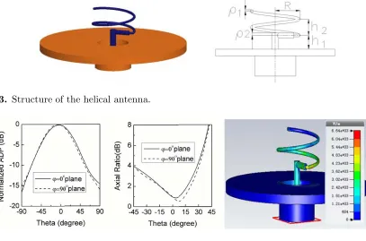
The low profile helical antenna used in [2, 4] has quite favorable radiation performance. However, the helix wire and horizontal wire need to be welded to joint together in the manufacture. This leads to unexpected dimension errors as well as coarse surface, which is unfavorable to the antenna radiation performance and power handling capacity. To overcome this problem, the structure of the helical antenna is optimized, as shown in Figure 3. The radius of the horizontal wire is bigger than that of the helix wire. In the manufacture, the helix wire and inner conductor of the horizontal wire are firstly wound by a mold. A sleeve with the inner radius equal to the helix wire radius and the outer radius equal to the horizontal wire radius is then bonded with the inner conductor of the horizontal wire by a conductive adhesive. Thus, the entire manufacture process has no welding, which improves the quality of the manufacture.
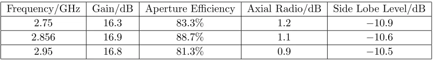
The optimization of the helical antenna is carried out by the software CST. The optimized dimensions of the helical can be summarized in Table 1 (Nis the number of helical turns). The calculated antenna directivity pattern (ADP), axial ratio, as well as electric field distribution at 2.856 GHz (the input power is 0.5 W for all electric field distribution simulations) is shown in Figure 4. It can be seen that this helical antenna can radiate circularly polarized microwave with a boresight peak. The
Figure 3. Structure of the helical antenna.
Figure 4. Normalized ADP, axial ratio and electric field distribution of the helical antenna.
Table 1. Optimized dimensions of the helical antenna.
Parameters R h1 h2 ρ1 ρ2 N
maximum electric field is approximately 6640 V/m. The breakdown threshold is taken to be 40 MV/m according to Kilpatrick criterion [7]. Hence, If we maintain the vacuum state in the helical antenna and ignore other breakdown factors, the power-handling capacity of single helical antenna reaches (406640×106)2×0.5 = 18 MW.
3.2. Design of the Feed System
The major characteristic of the feed system is that its output ports are arranged in triangular-grid. Compared with the 16-element rectangular-grid feed system, this 12-element triangular-grid feed system has six different groups of output ports instead of three. For each group of output ports, different kind of probes or different dimension of the probes should be designed and optimized. The design of this feed system is therefore more complicated.
The purpose of the feed system design is to obtain equal amplitudes for all output ports. In order to achieve this purpose, three kinds of probes are used to couple energy from the radial waveguide. Ports 3–4 use one-side post probes, as shown in Figure 2(e). Ports 9–10 and ports 11–12 use cylindrical based probes, as shown in Figures 2(g) and 2(b) respectively. Ports 1–2, ports 5–6 and ports 7– 8 use new probes, as shown in Figures 2(f), 2(c) and 2(d) respectively. The new probes shown in Figures 2(f), 2(c) and 2(d) are improved models of the L-shaped probes mentioned in reference [2, 4]. The three-dimensional structure of the new probe is shown in Figure 5. Compared with the L-shaped probe, it adds a rectangular conductor between the L-shaped conductor and the lower plate of the radial waveguide. With this rectangular conductor, the entire rectangular section of the probe and the cylindrical base of the probe can be fabricated together with the lower plate of the feed system. Otherwise, in the L-shaped probe, these three parts should be fabricated separately and be assembled together with screws, which brings assembly errors.
The characteristics of the probes can be approximately analyzed by being placed in a parallel-plate waveguide [2]. The typical characteristic of the new probe is simulated and shown in Figure 6 (assuming the input magnitude to be 1). This shows that the new probe has a small reflected magnitude and a smoothly changed coupled magnitude, which is suitable for energy coupling.
The feed system is then designed using these probes. The design procedure is almost the same as that in [4]. Table 2 specifies the optimized dimensions of the feed system. Figure 7 shows the simulated
Figure 5. Structure of the new probe. Figure 6. Characteristic of the new probe.
Table 2. Optimized dimensions of the feed system.
Parameters L1 L2 R1 H1 H2 R2
Values/mm 204.9 236.6 22.5 14.7 12.3 10.0
Parameters H3 L3 R3 H4 L4 L5
Values/mm 20.0 23.5 14.3 18.0 20.5 23.5
Parameters R4 H5 L6 R4 H6 H7
magnitude and phase for each output port of the feed system (assuming the input magnitude to be 1, the input phase to be 0◦). It can be seen that the output magnitudes and phases are divided into six groups according to their positions in the feed system. At 2.856 GHz, one can obtain a quasi-equal output magnitude distribution, and the output phases for ports 1–2, ports 3–4, ports 5–6, ports 7–8, ports 9–10 and ports 11–12 are−73◦,−142◦, 145◦, 90◦,−165◦, and 160◦ respectively. This characteristic permits us to use the sequential rotation technique to improve the circularly polarized performance of the antenna [8, 9]. The corresponding helical antennas might rotate according to the output phases to have the same radiation phase, as shown in Figure 1. It can be seen also that the imbalance of the output magnitude as well as the differences among output phases increase when the frequency deviates from 2.856 GHz. This fact might decrease the aperture efficiency of the antenna at these frequencies. The field distribution of the feed system is calculated and the result is shown in Figure 8. It can be seen that the maximum electric field is approximately 1500 V/m. If we maintain the vacuum state in the feed system, the power-handling capacity for this feed system could reach (401500×106)2×0.5 = 350 MW. This antenna is therefore suitable for high power application.
3.3. Antenna Performance
The array antenna model is accomplished by using the triangular-grid feed system to feed 12 helical antennas. This antenna is finalized based on the above-mentioned pertinent designs. The antenna
Figure 7. Simulated magnitude and phase for each output port of the feed system.
Figure 8. Simulated field distribution of the feed system.
Table 3. Measured performances of the antenna.
Frequency/GHz Gain/dB Aperture Efficiency Axial Radio/dB Side Lobe Level/dB
2.75 16.3 83.3% 1.2 −10.9
2.856 16.9 88.7% 1.1 −10.6
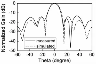
Figure 9. VSWR of the antenna. Figure 10. Normalized gain of the antenna.
performances are validated by simulations and experiments. Figure 9 shows the simulated and measured VSWR of the array antenna. The measured antenna VSWR is less than 1.2 over the frequency range of 2.75–2.95 GHz. Figure 10 shows the simulated and measured normalized gain pattern at 2.856 GHz inϕ= 0◦ and ϕ= 90◦ planes. Table 3 summarizes the measured performances of the antenna.
The measured results coincide approximately with the simulated ones, which prove that this antenna can realize a favorable radiation in the axial direction. The measured results show that in the range of 2.75–2.95 GHz, the antenna gain is over 16.3 dB, the antenna aperture efficiency is over 80%, the axial ratio is below 1.2 dB and the antenna side lobe level is below −10.5 dB. Compared with the antennas presented in [4, 5], this antenna realizes a triangular-grid array, which is helpful to reducing the number of elements demanded for a certain antenna aperture and grating lobe suppression capacity [10].
4. APPLICATION AS A SUB-ARRAY
In order to demonstrate the ability of this array to be used as a sub-array, a 6×8 big array is formed by combining four proposed arrays together, as shown in Figure 11. A four-way power divider is used to feed four sub-arrays.
The performances of the big array are investigated using the same method as that in [4]. Figure 12 shows the measured VSWR of the big array. Figure 13 shows the simulated and measured normalized gain patterns at 2.856 GHz in ϕ = 0◦ plane. Table 4 summarizes the measured performances of the big array and compares them with that of the sub-array. It can be concluded that the big array has a favorable performance. The aperture efficiency of the big array is a little less than that of the sub-array. This fact is mainly caused by the insertion loss of the power divider. Nevertheless, the results demonstrate the ability of the proposed array to be used as a sub-array.
Figure 12. VSWR of the big array. Figure 13. Normalized antenna gain pattern of the big array.
Table 4. Performances comparison of the big array and the sub-array.
Array Gain (dB) Aperture Efficiency Axial Radio (dB) Side Lobe Level (dB) VSWR
Big array 22.6 82.4% 1.3 −13.0 1.20
Sub-array 16.9 88.7% 1.1 −10.6 1.08
5. CONCLUSION
In this paper, a 12-element triangular-grid rectangular radial line helical array antenna is proposed and investigated. An antenna prototype with the center frequency of 2.856 GHz is designed and measured. It can realize favorable circularly polarized radiation at its axial direction and has quite high power-handling capacity. This triangular-grid array can reduce the number of elements demanded for a certain antenna gain and can be used to form high gain arrays.
ACKNOWLEDGMENT
The authors would like to thank the Fundamental Research Funds for the Central Universities (2682014ZT20) for their support in this research.
REFERENCES
1. Li, X. Q., Q. X. Liu, L. Zhao, J. Q. Zhang, and Z. Q. Zhang, “The high-power radial line helical array antenna,” 2008 World Automation Congress proceedings, Vols. 1–3, 961–965, 2008.
2. Li, X. Q., Q. X. Liu, X. J. Wu, L. Zhao, J. Q. Zhang, and Z. Q. Zhang, “A GW level high-power radial line helical array antenna,”IEEE Trans. Antennas Propag., Vol. 56, No. 9, 2943–2948, 2008. 3. Li, X. Q., Q. X. Liu, J. Q. Zhang, L. Zhao, and Z. Q. Zhang, “The high-power radial line helical circular array antenna: Theory and development,” 2010 International Conference on Microwave and Millimeter Wave Technology Proceedings, 671–674, 2010.
4. Li, X.-Q., Q.-X. Liu, J.-Q. Zhang, and L. Zhao, “16-element single-layer rectangular radial line helical array antenna for high-power applications,” IEEE Antennas and Wireless Propagation Letters, Vol. 9, 708–711, 2010.
5. Li, X.-Q., Q.-X. Liu, and J.-Q. Zhang, “Double-layer radial line helical array antenna with rectangular aperture,”Progress In Electromagnetics Research Letters, Vol. 31, 15–24, 2012. 6. Kraus, J. D. and R. J. Marhefka, Antenna: For All Application, McGraw-Hill, New York, 2002. 7. Jameson, R. A., “High brightness RF linear accelerators,” Proc. ASI Conf. on High Brightness
8. Teshirogi, T., M. Tanaka, and W. Chujo, “Wideband circularly polarized array antenna with sequential rotations and phase shift of elements,”Int. Symp. on Ant. and Prop., 1985.
9. Huang, J., “A technique for an array to generate circular polarization with linear polarized elements,” IEEE Trans. Antennas Propag., Vol. 34, No. 9, 1113–1124, Sep. 1986.