ISSN Online: 2327-5227 ISSN Print: 2327-5219
DOI: 10.4236/jcc.2018.612004 Dec. 26, 2018 49 Journal of Computer and Communications
High-Power 30-Element Helical Antenna Array
Yuan Liang, Qingxiang Liu
School of Physical Science and Technology, Southwest Jiaotong University, Chengdu, China
Abstract
A new radial-line helical array (RLHA) using dual-branch helical antennas has been designed for improving the power capacity of RLHAs. The helical element is cavity-backed to lower the mutual coupling and its power capacity is higher than the conventional ones. The components of the proposed array are discussed and the power capacity is obtained by simulation. Compared with the typical RLHAs, the proposed sub-array has not only higher power capacity but also uses fewer elements. Experimentally, the measured results of an array prototype indicate that high gain as well as circular polarization has been successfully achieved.
Keywords
Helical Antenna, Antenna Array, High Power, Circular Polarization
1. Introduction
High power antennas are important to high power microwave (HPM) systems and they are of special concerns in power handling capacity. Constantly, insu-lating gas or vacuum conditions are also required for high breakdown threshold. Along with the development of HPM technology, there is noticeable improve-ment on the output power of narrowband HPM sources [1], the peak power could be as high as GW-class even though at high frequency bands. On the other hand, a lot of high power antenna arrays have been investigated so that the per-formance of HPM sources can be fully exploited. The high power elements, such as horns [2] [3], slots [4] [5] and helixes [6] [7] [8], are used for researches. When excited, the input power will be distributed to a number of antenna ele-ments. The horn antennas have high power capacity but they are not suitable for compact design [3]. As for the slots, it is difficult to use high power phase shif-ters for the antenna elements [5]. The RLHA is more preferable among those HPM antennas, this kind of array is considered having high power capacity, low How to cite this paper: Liang, Y. and Liu,
Q.X. (2018) High-Power 30-Element Heli-cal Antenna Array. Journal of Computer and Communications, 6, 49-55.
https://doi.org/10.4236/jcc.2018.612004
DOI: 10.4236/jcc.2018.612004 50 Journal of Computer and Communications
nique instead of coupling probes to feed the elements, the power capacity was 416 MW at 14.25 GHz. These above-mentioned arrays have shown great high power characteristics due to the small E-field strength and high breakdown threshold.
However, the power capacity of the conventional helical element is the limita-tion. As the output power of HPM sources become higher, the breakdown phe-nomena will occur more easily at the helical elements, so there is a pressing need to improve the power capacity of them. For this reason, we present a high power helical array by using dual-branch helical antennas [9] (DBHA), but the helical element has been cavity-backed for low mutual coupling in array circumstance. Its characteristics will be shown via simulation and experiment.
2. Antenna Design
2.1. Helical Element
For a RLHA, the axial-mode short helical antenna is chosen to be the antenna element, hence the array is also circularly polarized. These antenna elements are placed on the upper side of the radial-line, and the waveguide wall transforms into a reflecting plate. Even though the output phases of the probes may be dif-ferent, bore sight peak can be realized by rotating the helical elements.
The power capacity of antenna element is the key for a RLHA, but the con-ventional single-branch helical antenna (SBHA) element lacks of sufficient pow-er capacity as the output powpow-er of the HPM sources becomes highpow-er nowadays. The DBHA was put forward to lower the maximum E-field over the helical arms. It consists of two independent helixes, between which there is a relative rotation angle to adjust the phase difference, then the radiation path is divided into two. As the current amplitude over the helical arms decreases, the maximum E-field of the helical antenna becomes smaller. Specifically, the feed line and radiation characteristics of DBHA are the same as SBHA, it is feasible for DBHA to re-place SBHA so as to improve the power capacity of RLHA.
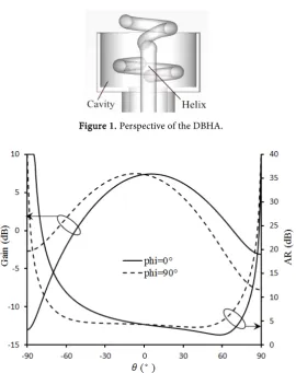
Because the DBHA prototype is not able to be applying in array directly [9], so it has been cavity-backed to strengthen its independence. Figure 1 shows the perspective of the heliacal element model. In order to accommodate for array application, the element is optimized with periodic boundary using CST Micro-wave Studio (the input power is 0.5 W). Figure 2 plots that the gain of the cavi-ty-backed DBHA is 7.4 dB and the axial ratio (AR) is 4.2 dB at θ = 0˚. Although the AR is not small enough, better value will be achieved in the helical array [10].
DOI: 10.4236/jcc.2018.612004 51 Journal of Computer and Communications
Figure 1. Perspective of the DBHA.
Figure 2. Far-field characteristics of one DBHA.
since most of the microwave energy is restricted inside the cavity and then ra-diates outside, the current density of the upper helical arm will be higher if all the energy radiated from the lower helix passes the upper. In addition, even though maximum E-field of the helical element has been well optimized, it is difficult to guarantee uniform amplitude feeding for each element, the E-field might continue to change after assembling the elements and the feed line.
The optimized parameters of the cavity-backed DBHA are listed in Table 1. Here the parameters are defined as follows: R is radius of the helix, S is the pitch,
ρ is diameter of the helical arm, t is turn of the helix, θ0 is the relative rotation angle, h0 is height between the two feed points, hc is height of the cavity, and dc is diameter of the cavity.
2.2. Helical Array
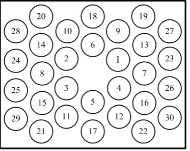
As shown in Figure 3, a 30-element array prototype has been designed to verify the characteristics of DBHA, the elements are arranged on triangular grid and the same to the probes in the feed line.
DOI: 10.4236/jcc.2018.612004 52 Journal of Computer and Communications
Figure 3. Output ports distribution of the array.
Table 1. Dimensions of the cavity-backed DBHA.
Parameter R1 R2 S1 S2 ρ1 ρ2
Value 4.5 mm 5.8 mm 2.7 mm 2.7 mm 2.3 mm 2.45 mm
Parameter t1 t2 θ0 h0 hc dc
Value 0.7 0.77 60˚ 5.4 mm 10 mm 19.2 mm
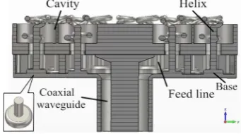
for those in the same group, but it means that in different groups are not. The purpose of the feed line design is to obtain uniform output amplitude for the ports, but the imbalance of output magnitude will increase when the frequency deviates from the center, this might decrease the aperture efficiency of the an-tenna at these frequencies. In order to handle with this, cylindrical-base probes are used to couple energy from the radial waveguide. As diagramed in Figure 4, the cylindrical-base probe increases its coupling coefficient by adjusting the pa-rameters of the cylindrical base, which provides much more surface areas to en-hance the coupling coefficient. With this metal base, excessive reflection will be introduced but it is acceptable before the height of it gets overlarge. The base and the probe are fabricated together onto the bottom of the feed line. Other-wise, these components should be fabricated separately and be assembled to-gether with screws, which could bring assembly errors.
[image:4.595.207.541.270.338.2]DOI: 10.4236/jcc.2018.612004 53 Journal of Computer and Communications
[image:5.595.269.478.203.331.2]Figure 4. Cross-section of the array.
Figure 5. Coupling characteristic of the probe.
Figure 6. E-field distribution of the array.
Table 2. Comparison for typical RLHAs and the proposed array.
Li [6] Pottier [7] This paper
Number of elements 48 80 30
Frequency 4 GHz 9.3 GHz 9.7 GHz Power capacity 1 GW 500 MW 885 MW
[image:5.595.269.480.363.516.2] [image:5.595.208.540.567.635.2]DOI: 10.4236/jcc.2018.612004 54 Journal of Computer and Communications
[image:6.595.273.477.73.236.2]Figure 7. VSWR results.
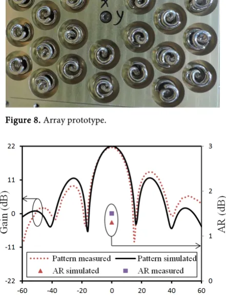
Figure 8. Array prototype.
Figure 9. Far-field characteristics of the array.
[image:6.595.263.484.331.620.2]DOI: 10.4236/jcc.2018.612004 55 Journal of Computer and Communications
3. Conclusion
The design of a 30-element triangular-grid helical antenna array was de-scribed and it showed higher power capacity by aid of using the cavity-backed dual-branch helical antennas. The simulated results of the array showed that the power capacity was noticeably high, and it has achieved the expectant directional radiation and circular polarization. As a result of higher power the array could handle, it is feasible that we use dual-branch helical antennas for high power ap-plications.
Conflicts of Interest
The authors declare no conflicts of interest regarding the publication of this pa-per.
References
[1] Hamamah, F., et al. (2017) High Power Microwave Devices: Development since 1880. 2017 IEEE Asia Pacific Microwave Conference (APMC), Kuala Lumpur, 825-828. https://doi.org/10.1109/APMC.2017.8251576
[2] Rahmat-Samii, Y., et al. (1992) Canonical Examples of Reflector Antennas for High-Power Microwave Applications. IEEE Transactions on Electromagnetic Compatibility, 34, 197-205. https://doi.org/10.1109/15.155830
[3] Lee, J.M. and Woo, J.M. (2012) Design of Array Synthesis Horn Antenna for High-Power Microwave Applications. Proc. PIER, 1196-1198.
[4] Zhao, X.L., et al. (2017) All-Metal Transmit-Array for Circular Polarization Design Using Rotated Cross-Slot Elements for High-Power Microwave Applications. IEEE Transactions on Antennas and Propagation, 65, 3253-3256.
https://doi.org/10.1109/TAP.2017.2691460
[5] Peng, S.R., et al. (2015) Design of a Concentric Array Radial Line Slot Antenna for High-Power Microwave Application. IEEE Transactions on Plasma Science, 43, 3527-3529. https://doi.org/10.1109/TPS.2015.2392097
[6] Li, X.Q., et al. (2008) A GW Level High-Power Radial Line Helical Array Antenna. IEEE Transactions on Antennas and Propagation, 56, 2943-2948.
https://doi.org/10.1109/TAP.2008.928781
[7] Pottier, S.B., et al. (2014) High Pulsed Power Compact Antenna for High-Power Microwaves Applications. IEEE Transactions on Plasma Science, 42, 1515-1521.
https://doi.org/10.1109/TPS.2014.2321416
[8] Yu, L.Z., et al. (2017) Design of a Slot-Coupled Radial Line Helical Array Antenna for High Power Microwave Applications. AIP Advances, 7, Article ID: 095101. [9] Liang, Y., Zhang, J.Q., Liu, Q.X. and Li, X.Q. (2018) High Power Dual-Branch
Hel-ical Antenna. IEEE Antennas and Wireless Propagation Letters, 17, 472-475.
https://doi.org/10.1109/LAWP.2018.2796244
[10] Huang, J. (1986) A Technique for an Array to Generate Circular Polarization with Linearly Polarized Elements. IEEE Transactions on Antennas and Propagation, 34, 1113-1124. https://doi.org/10.1109/TAP.1986.1143953
[11] Kilpatrick, W.D. (1957) Criterion for Vacuum Sparking Designed to Include Both RF and DC. Review of Scientific Instruments, 28, 824-826.