ECRH/EBWH SYSTEM FOR NSTX-U
G. Taylor1, R.A. Ellis1, R.W. Harvey2, J.C. Hosea1, and A.P. Smirnov3
1Princeton Plasma Physics Laboratory, Princeton University, Princeton, NJ 08543, USA 2CompX, Del Mar, CA 92014, USA
3M.V. Lomonosov Moscow State University, Moscow, Russia
Abstract. The National Spherical Torus Experiment Upgrade (NSTX-U) will operate at an axial toroidal field of up to 1 T, about twice the field available on NSTX. A 28 GHz electron cylotron resonance heating (ECRH) system is currently being planned for NSTX-U. A 1 MW 28 GHz gyrotron will be employed. Intially the system will use short, 10-50 ms, 1 MW pulses for ECRH-assisted discharge start-up. Later the pulse length will be extended to 1-5 s to study electron Bernstein wave heating (EBWH) during the plasma current flat top. A mirror launcher will be used to couple microwave power to the plasma via O-mode to the slow X-mode to EBW (O-X-B) double mode conversion. This paper presents a pre-conceptual design for the ECRH/EBWH system proposed for NSTX-U and includes ray tracing and Fokker-Planck modeling results for 28 GHz ECRH during plasma start-up and EBW heating and current drive during the plasma current flattop of a NSTX-U advanced H-mode plasma scenario.
1 Introduction
The National Spherical Torus Experiment (NSTX) [1] is being upgraded to NSTX-U, a device that will have double the toroidal field, plasma current and neutral beam injection (NBI) power, and a pulse length of 5-8 s, five times the pulse length of NSTX [2]. In NSTX-U the maximum axial toroidal field will be 1 T, and the maximum plasma current will be 2 MA. For reactor-relevant spherical torus operation it is critical to develop discharge initiation, plasma current ramp-up, and plasma sustainment techniques that do not require a central solenoid. One of the major long-term goals of the NSTX-U research program is fully non-inductive plasma current ramp-up and sustainment. Non-inductive plasma start-up will be accomplished through a combination of coaxial helicity injection (CHI) [3], outer poloidal field start-up [4], plasma guns [5], and up to 1 MW of 28 GHz electron cyclotron resonance heating (ECRH). After the plasma becomes overdense for ECRH, the plasma current will be ramped up by bootstrap current and direct current drive using high-harmonic fast-wave heating and neutral beam injection. Earlier modeling of a high β, 100% non-inductive plasma scenario in NSTX [6] during the plasma current flat top showed that off-axis EBW current drive [7] can help to stabilize the plasma equilibrium. An upgrade of the 1 MW 28 GHz ECRH system to a 2 MW electron Bernstein wave (EBW) heating and current drive system is being considered for later implementation on NSTX-U. The pre-conceptual design of the 28 GHz ECRH and EBW heating and current drive systems for NSTX-U is presented in section 2. In section 3.1 ECRH modeling results are presented for a CHI start-up discharge, and in section 3.2 modeling EPJ Web of Conferences
DOI: 10.1051/ C
Owned by the authors, published by EDP Sciences, 2012 ,
epjconf 201232/
020 (2012)
02 32
0 14 14
results are presented for EBW heating and current drive during the plasma current flat top of an advanced scenario NSTX-U H-mode plasma.
2 Design of the NSTX-U 28 GHz Heating System
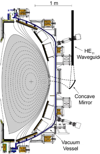
The 28 GHz gyrotron being considered for the NSTX-U ECRH/EBWH system was developed for for ECRH on the GAMMA10 tandem mirror [8]. The gyrotron has an output power of 1 MW, a pulse length of 1-5 s and uses a TE8,3 cavity mode. The gyrotron will be powered by a modified TFTR neutral beam power supply [9] located in the former TFTR test cell located next to NSTX-U. The 28 GHz power will be transmitted to NSTX-U via a low-loss, 50 mm diameter, corrugated HE1,1 waveguide. Figure 1 shows a poloidal cross section of the NSTX vacuum vessel and a typical plasma equilibrium. For the ECRH-assisted plasma start-up experiments the low-loss waveguide will be connected to a corrugated horn antenna located on the midplane of the vacuum vessel. The heating pulse duration used for the plasma start-up experiments will be 10-50 ms. For EBW heating and current drive studies during the plasma current flattop the gyrotron pulse length will be increased to 1-5 s, and a second 1 MW gyrotron will be installed. Coupling to the EBWs in the plasma will be accomplished via O-mode to slow X-mode to EBW (O-X-B) double mode conversion [10-12]. An actively-cooled, concave steerable mirror launcher with a focal length of about 45 cm, capable of withstanding a 5 s duration, 2 MW heating pulse, will focus the 28 GHz power on the EBW mode conversion layer. To generate EBW current drive, in addition to EBWH, the focal spot will be poloidally offset from the midplane to introduce a parallel wavenumber (n//) upshift in the plasma.
3 Modeling Results
The GENRAY [13] ray tracing code, and the ADJ [14] Fokker-Planck code were used to model the second harmonic 28 GHz X-mode ECRH in a NSTX CHI start-up plasma with an axial toroidal field, BT(0) = 0.5 T, (section 3.1) and fundamental 28 GHz EBW heating and current drive in a NSTX-U BT(0) = 1 T advanced scenario H-mode plasma (section 3.2).
3.1 ECRH Modeling Results for a CHI Start-up Discharge
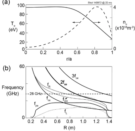
Figure 2(a) shows the electron density and temperature profiles that were used for GENRAY modeling of ECRH during a CHI start-up discharge. The electron temperature profile of a CHI discharge is typically extremely hollow. In this case the electron temperature profile peaks well off axis and is only 5 eV near the magnetic axis. The central electron density is 4 x 10¹⁸ m-3 and the
density profile is broad. As shown in Fig. 2(b), 28 GHz microwave power is resonant with the second harmonic cyclotron resonance (2fce) at a major radius (R) of 0.9 m. The right hand cutoff (fR) is just below 28 GHz at R = 0.9 m.
100 rays were used for the GENRAY modeling. The ECH antenna orientation was adjusted for maximum first pass absorption. Figure 3 shows the ray trajectories calculated by GENRAY when the antenna is pointing 5 degrees down and 1 degree right of the normal of the ECRH port. Figure 3(a) shows the rays projected onto the poloidal cross section and Fig. 3(b) shows rays projected onto the toroidal midplane (Fig. 3(b)). Rays are plotted until they reach the outboard last closed flux surface (LCFS) after reflecting off of the right hand cutoff. This antenna orientation yielded the maximum first pass absorption. The power deposition profile calculated by GENRAY (Fig. 3(c)) is very narrow and located at a normalized minor radius, r/a ~ 0.17 on the low field side of the magnetic axis.
Figure 4(a) shows the dependence of the first pass absorption on toroidal launch angle when the antenna is pointing 5 degrees down. The peak first pass absorption reaches 27% with the antenna pointed 1 degree from normal to the plasma surface, then falls to 10-15% as the toroidal angle is increased from 3 to 8 degrees. The actual absorption will
Fig. 2 (a) Electron density (solid line) and temperature (dashed line) profiles used for the GENRAY ECRH modeling, derived from multi-point Thomson scattering data acquired at 20 ms during NSTX CHI shot 148072. (b) Electron cyclotron resonances and cutoffs on the midplane of shot 148072 calculated using magnetic equilibrium data at 22 ms and the density profile data of Fig. 2 (a).
Fig. 3 Ray trajectories calculated by GENRAY plotted in (a) the poloidal and (b) the toroidal midplane for the case with maximum first pass absorption of 28 GHz ECRH at 20 ms during NSTX CHI shot 148072, with the antenna pointing 5 degrees down and 1 degree right of the normal to the ECRH port. (c) First pass power deposition profile versus normalized minor radius (r/a) calculated by GENRAY for 1 MW of 28 GHz.
be enhanced significantly by wall reflections.
Figure 4(b) shows the effect of increasing the electron temperature on the first pass absorption. The actual central temperature of the CHI plasma, 5 eV, is highlighted. First pass absorption is predicted to increase to 60-80% as the central electron temperature increases to 100-200 eV.
3.2 EBW Modeling Results for an NSTX-U Advanced Scenario H-Mode Plasma
GENRAY-ADJ modeling was
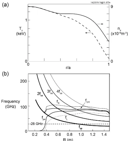
conducted for a 1.1 MA advance scenario NSTX-U H-mode plasma with an axial toroidal toroidal field of 1 T that was modeled by TRANSP [15] (TRANSP run 142301V11 at 11.875 s). The density and temperature profiles used for the modeling are shown in Fig. 5 (a). The electron cyclotron resonances and cutoffs for this plasma are shown in Fig. 5(b). 28 GHz EBWs are resonant with fce at R ~ 0.95 m, close to the magnetic axis.
The O-X-B mode conversion efficiency was calculated as a function of poloidal and toroidal angle for TRANSP run 142301V11 at 11.875 s and the results are summarized in Fig. 6. The maximum O-X-B mode conversion efficiency was obtained for a poloidal angle of ± 10 degrees and a toroidal angle of ± 38 degrees, corresponding to n// = ± 0.7. Modeling
Fig. 4 (a) First pass absorption fraction plotted versus the toroidal angle between the antenna axis and the normal to the plasma surfacewhen the antenna is pointing 5 degrees down, and (b) the dependence of first pass absorption on electron temperature when the antenna is pointing with a toroidal angle of 1 degree to the normal to the plasma surface and 5 degrees down.
calculations of the EBW heating and current drive assumed a launched n// = ± 0.7. The EBW rays were launched at the LCFS and the vertical location of the launched rays was scanned above and below the midplane. The optimum location for providing localized heating and current drive was found between 15 and 25 degrees above and below the midplane.
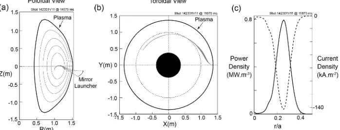
Figure 7 summarizes GENRAY-ADJ modeling results for 1 MW of EBW power launched 20 degrees below the midplane with n// = 0.7. EBWs propagate to just inside the magnetic axis (Fig. 7(a)) and travel about a third of the way toroidally around the machine (Fig. 7(b)). EBW power deposition peaks at r/a ~ 0.25. In this case the EBW-driven current is 25 kA and it is driven counter to the ohmic plasma current. Launching 20 degrees above the midplane drives a similar
current but in the same direction as the ohmic plasma current. Launching the EBW power less than 10 degrees above and below the midplane resulted in little or no net current drive since the n// of the propagating EBWs oscillated between positive and negative values as they were absorbed, and as a result drove current in both directions. Launching the EBW power more than 30 degrees above and below the midplane resulted in large Doppler shifts, so that the EBW power was absorbed well off axis and the EBW power deposition profile became very broad.
Previously B-X-O radiometric measurements on NSTX had yielded 50-60% EBW coupling efficiency from H-mode plasmas [16] with the coupling losses being dominated by EBW collisional losses near the B-X-O mode conversion layer, that was located in the plasma scrape off. The higher
Fig. 6 O-X-B mode conversion efficiency versus poloidal and toroidal angle for NSTX-U TRANSP run 142301V11 at 11.875 s. GENRAY-ADJ modeling was performed assuming a launched n// = ± 0.7, corresponding to alignment of the mirror launcher with the indicated regions of maximum mode conversion.
Fig. 7 EBW ray trajectories calculated by GENRAY-ADJ plotted in (a) the poloidal and (b) the toroidal midplane for a case with maximum OXB conversion efficiency for NSTX-U TRANSP run 142301V11 at 11.875 s. EBW rays were launched 20 degrees below the midplane with n// = 0.7. (c) EBW power deposition and EBW-driven current density versus r/a calculated by GENRAY-ADJ for 1 MW of 28 GHz EBW power.
magnetic field on NSTX-U should yield higher scrape off temperatures and lower EBW collisonal losses, and as a result a better O-X-B coupling efficiency.
Acknowledgement
This work was supported under United States Department of Energy contract number DE-AC02-09CH11466.
References
1. M. Ono, et al., Nucl. Fusion 41, 1435 (2001)
2. J.E. Menard, et al., Proc. 37th EPS Conf. on Plasma Physics (2010), paper P2.106 3. R. Raman, et al., Nucl. Fusion 47, 792 (2007)
4. W. Choe, et al., Nucl. Fusion 45, 1463 (2005) 5. D. J. Battaglia, et al., J. Fusion Energy 28, 140 (2009) 6. C. E. Kessel, et al., Phys. Plasmas 13, 056108 (2006) 7. G. Taylor, et al, Phys. Plasmas 11, 4733 (2004)
8. T. Kariya, et al, J. Infrared, Millimetre and Terahertz Waves 32, 295 (2011)
9. D. Hopkins, et al., Proc. 7th Symposium on Engineering Problems of Fusion Research Vol. 2, Inst. of Electrical and Electronic Engineers (1977) pp. 1570-1577
10. J. Preinhaelter and V. Kopécky, J. Plasma Phys. 10, 1 (1973) 11. E. Mjolhus, J. Plasma Phys. 31, 7 (1984)
12. F. R. Hansen, J. P. Lynoc, C. Maroli, and V. Petrillo, J. Plasma Phys. 39, 319 (1988) 13. A. P. Smirnov and R.W. Harvey, Bull. Am. Phys. Soc. 40, 1837 (1995)
14. A. P. Smirnov, et al., Proc. 15th Workshop on ECE and ECRH, World Scientific (2009), pp. 301-306
15. R. J. Hawryluk, in “Physics of Plasmas Close to Thermonuclear Conditions”, Proc. of the International School of Plasma Physics, (Pergamon, Varenna, Italy, 1981) 1, p. 19