MODELING AND SIMULATION OF THREE-PHASE
MATRIX CONVERTER USING MATLAB
Rajesh Kr Ahuja
1, Pankaj Kumar
2,Lalit Agarwal
31,2,3
Associate professor, Electrical Engineering Department, YMCAUST, Faridabad, (India)
ABSTRACT
This paper addresses about the performance of the matrix converter which is the direct AC-AC converter. Matrix
converter consists of an array of controlled semi conductor switches that connects directly the three phase source to
the three phase load. The gating signals for the semi–conductor switches are produced using space vector
modulation for three phase matrix converter. Simulation of matrix converter feeding different loads is carried out in
MATLAB/SIMULINK .The simulation results like output phase voltage, output phase current, input current, rotor
speed, and electromagnetic torque at resistive, inductive and dynamic loads are presented in this paper.
Keywords:MATLAB/SIMULINK, Matrix converter, Pulse width modulation, Simulation, Space vector modulation
I INTRODUCTION
Most of all industrial applications are depended on ac to ac power conversion. The ac to ac converters are widely
used in the industry application because of its ease of use and provide the output voltage and current of desired
magnitude. The ac to ac converter takers takes power from one ac system and delivers it to another ac system with
the waveform having different amplitude, frequency, and phase. There are two ac to ac converter i.e. indirect
converters and direct converter. Indirect converter are those converters which utilize a dc link between the two ac
systems and direct converters are those which provide direct conversion. Matrix converter provides the direct
conversion from ac to ac. The matrix converter is a single-stage converter which has an array of p×q bidirectional
power switches to connect, directly, a p -phase voltage source to a q-phase load. It does not have any DC-link circuit
and does not need any large energy storage elements. It consist of nine bi-directional switches which are arranged as
three sets of three so that any of the three input phases can be connected to any of the three output lines. These
bi-directional switches are capable of providing fully four quadrant operation to the matrix converter and these are
regarded as a key element for the operation of matrix converter.
II MODULATION TECHNIQUE
The purpose of these modulation techniques is to change the voltage transfer ratio. There are different types of
modulation technique, Scalar modulation technique, Space vector modulation technique, indirect modulation
technique. The main modulation techniques which have wide applications are Venturini modulation technique and
the space vector modulation technique. In this paper space vector modulation is used for producing the gating
signals for three phase matrix converter.
2.1 Control Scheme For Three Phase Matrix Converter
The object of the modulation strategy is to synthesize the output voltages from the input voltages and the input
currents from the output currents matrix converter can be represented by a 3 by 3 matrix form because the nine
bidirectional switches can connect one input phase to one output phase directly without any intermediate energy
storage elements. Therefore, the output voltages and input currents of the matrix converter can be represented by the
transfer function T and the transposed TT such as:
Where Va, Vb and Vc are input phase voltages, VA, VB and VC are output phase voltages, Ia, Ib and Ic are input currents and IA, IB and IC are output currents.
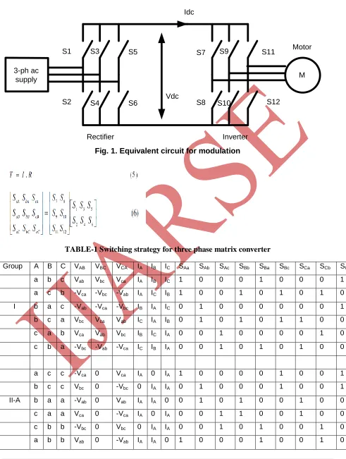
The indirect space vector modulation is gaining as a standard technique in the matrix converter modulations. Matrix
converter can be considered to be equivalent to the circuit combining current source rectifier and voltage source
inverter connected through virtual dc link as shown in Fig.1. Inverter stage has a standard voltage source inverter
topology consisting of six switches, S7 to S12 and rectifier stage has the same power topology with another six switches, S1 to S6.
The basic idea of the indirect modulation technique is to decouple the control of the input current and the control of
the output voltage. This is done by splitting the transfer function T for the matrix converter in into the product of a
Rectifier Inverter S1 S2 S3 S4 S5 S6 S7 S8 S9 S10 S11 S12 M Vdc Idc 3-ph ac supply Motor
Fig. 1. Equivalent circuit for modulation
TABLE-1 Switching strategy for three phase matrix converter
Group A B C VAB VBC VCA IA IB IC SAa SAb SAc SBb SBa SBc SCa SCb SCc
a b c Vab Vbc Vca IA IB IC 1 0 0 0 1 0 0 0 1
a c b -Vca -Vbc -Vab IA IC IB 1 0 0 1 0 1 0 1 0
I b a c -Vab -Vca -Vbc IB IA IC 0 1 0 0 0 0 0 0 1
b c a Vbc Vca Vab IC IA IB 0 1 0 1 0 1 1 0 0
c a b Vca Vab Vbc IB IC IA 0 0 1 0 0 0 0 1 0
c b a -Vbc -Vab -Vca IC IB IA 0 0 1 0 1 0 1 0 0
a c c -Vca 0 Vca IA 0 IA 1 0 0 0 0 1 0 0 1
b c c Vbc 0 -Vbc 0 IA IA 0 1 0 0 0 1 0 0 1
II-A b a a -Vab 0 Vab IA IA 0 0 1 0 1 0 0 1 0 0
c a a Vca 0 -Vca IA 0 IA 0 0 1 1 0 0 1 0 0
c b b -Vbc 0 Vbc 0 IA IA 0 0 1 0 1 0 0 1 0
c a c Vca -Vca 0 IB 0 IB 0 0 1 1 0 0 0 0 1
c b c -Vbc Vbc 0 0 IB 0 0 0 1 0 1 0 0 0 1
II-B a b a Vab -Vab 0 IB IB IB 1 0 0 0 1 0 1 0 0
a c a -Vca Vca 0 IB 0 IB 1 0 0 0 0 1 1 0 0
b c b Vbc -Vbc 0 0 IB IB 0 1 0 1 0 1 0 1 0
b a b -Vab Vab 0 IB IB 0 0 1 0 0 0 0 0 1 0
c c a 0 Vca -Vca IC 0 IC 0 0 1 0 0 1 1 0 0
c c b 0 -Vbc Vbc 0 IC IC 0 0 1 0 0 1 0 1 0
II-C a a b 0 Vab -Vab IC IC 0 1 0 0 1 0 0 0 1 1
a a c 0 -Vca Vca IC 0 IC 1 0 0 1 0 0 0 0 1
b b c 0 Vbc -Vbc 0 IC IC 0 1 0 0 1 0 1 0 0
b b a 0 -Vab Vab IC IC 0 0 1 0 0 1 0 0 0 0
a a a 0 0 0 0 0 0 1 0 0 1 0 0 1 0 0
III b b b 0 0 0 0 0 0 0 1 0 0 1 0 1 0
c c c 0 0 0 0 0 0 0 0 1 0 0 1 0 0 1
Where the matrix I is the inverter transfer function and the matrix R is the rectifier transfer function. This way to
model the matrix converter provides the basis to regard the matrix converter as a back-to back PWM converter
without any dc-link energy storage.
The above transfer matrix exhibits that the output phases are compounded by the product and sum of the input
phases through inverter switches S7 to S12 and rectifier switches S1 to S6. Therefore the indirect modulation
III SIMULATION RESULTS
The system consists of a three-phase matrix converter constructed from nine back-to-back IGBT switches. The
Matrix converter is supplied by an ideal 400V, 50Hz three-phase source and drives a static resistive load and
inductive load. The switching algorithm is based on an indirect space-vector modulation in which it considers the
Matrix converter as a rectifier and inverter connected via a DC link with no energy storage. Indirect space-vector
modulation allows direct control of input current and output voltage and hence allows the power factor of the source
to be controlled. The simulation is carried out in MATLAB/Simulink environment.
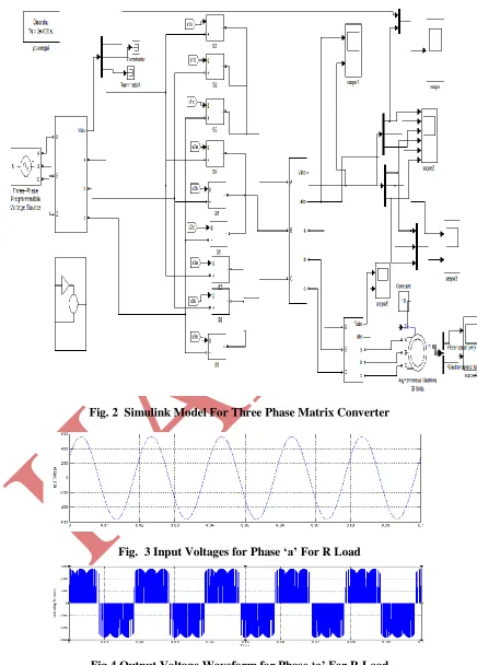
Fig. 2 shows the simulink model for the three phase matrix converter. It consists of nine bidirectional switches of IGBT’s. With proper gating signal to the gate terminal of the IGBT’S and with proper control of operation output
voltage will be generated across the load.
3.1 With R Load
Fig. 3 shows the input voltage for phase a is supplied to the matrix converter and further waveforms shows the
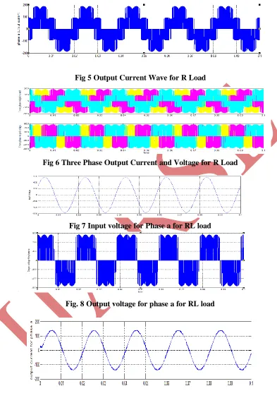
simulation results obtained for the R load for the matrix converter. Fig. 4 shows the output voltage for phase ‘a’ Fig.
5 shows the output current for phase ‘a’ and Fig. 6 shows the output voltage and output current for three phases.
3.2 With RL Load
Fig. 7 shows the input voltage for phase ‘a’ which is supplied to the matrix converter and further waveforms shows
the simulation results obtained for the RL load for the matrix converter. Fig. 8 shows the output voltage for phase ‘a’
Fig. 9 shows the output current for phase ‘a’ and Fig.. 10 shows the output voltage and output current for three
phases.
3.3 With Dynamic Load (3-ph Induction Motor load of 4kW)
Figures given below are simulation results for the induction motor which is connected as a load to the matrix
converter. The induction motor is supplied by the matrix converter. Fig. 11 shows the rotor speed of the induction
motor. By proper controlling of the matrix converter the speed of the induction motor can be controlled. Fig. 12
shows the electromagnetic torque for the electromagnetic torque. It can be seen that when electromagnetic and load
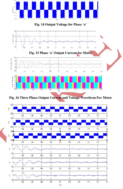
torque becomes equal then the speed of the rotor becomes constant. Fig. 13 shows the input supply voltage for phase
a. Fig.14 shows the output voltage for phase ‘a’ and from Fig. 13 and Fig. 14 comparison between the input and
output voltage can be seen. Fig. 15 shows the output current for phase a. Fig. 16 shows the three phase output
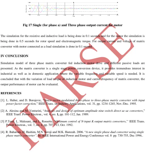
current and voltage Fig. 17 shows the output current for the single phase and three phases. Fig. 18 shows the output
Fig. 2 Simulink Model For Three Phase Matrix Converter
Fig. 3 Input Voltages for Phase ‘a’ For R Load
Fig 5 Output Current Wave for R Load
Fig 6 Three Phase Output Current and Voltage for R Load
Fig 7 Input voltage for Phase a for RL load
Fig. 8 Output voltage for phase a for RL load
.
Fig 10 Three Phase Output Current and Voltage Waveform for RL Load
Fig 11 Rotor Speed
Fig 12 Electromagnetic torque
Fig. 14 Output Voltage for Phase ‘a’
Fig. 15 Phase ‘a’ Output Current for Motor
Fig. 16 Three Phase Output Current and Voltage Waveform For Motor
Fig 17 Single (for phase a) and Three phase output current for motor
The simulation for the resistive and inductive load is being done in 0.1 seconds and for the motor the simulation is
being done in 0.5 seconds for rotor speed and electromagnetic torque. For output current and voltage of matrix
converter with motor connected as a load simulation is done in 0.1 second.
IV CONCLUSION
Simulation model of three phase matrix converter fed induction motor drive and different passive loads are
presented. As the matrix converter is a single stage power conversion device, it provides tremendous interest in
industrial as well as in domestic application where the variable frequency and variable speed is needed. It is
concluded that with the variation of load torque of induction motor and carrier frequency of matrix converter, the
output performance of motor can be evaluated.
REFERENCES
[1]. L. Huber, and D. Borojevic, “Space vector modulated three-phase to three-phase matrix converter with input power factor correction,” IEEE Trans. on Industry Applications, vol. 31, pp. 1234-1245, Nov./Dec. 1995.
[2] A. Alesina and M. Venturini, “Analysis and design of optimum amplitude nine-switch direct ac-ac converters,”
IEEE Trans. Power Electron., vol. 4, no. 1, pp. 101-112, Jan. 1989.
[3] P.Tenti, L. Malesani, and L. Rossetto, “Optimum control of N-input K-output matrix converters,’’ IEEE Trans.
Power Electron., vol. 7, no. 4, pp. 707-713, Oct. 1992.