Article
Material Design and Performance Evaluation of Foam
Concrete for Digital Fabrication
Viacheslav Markin, Venkatesh Naidu Nerella, Christof Schröfl, Gyunay Guseynova and Viktor Mechtcherine*
Technische Universität Dresden, Institute for Construction Materials, 01602 Dresden, Germany; * Correspondence: [email protected]; Tel.: +49-351-463-36311
Abstract: 3D-printing with foam concrete, which is known for its distinct physical and mechanical properties, has not yet been purposefully investigated. The article at hand presents a methodological approach for the mixture design of 3D-printable foam concretes and a systematic investigation of the potential application of this type of material in digital construction. Three different foam concrete compositions with water-to-binder ratios between 0.33 and 0.36 and having densities of 1100 to 1580 kg/m³ in the fresh state were produced with a pre-foaming technique using a protein-based foaming agent. Based on the fresh-state tests, including 3D-printing as such, an optimum composition was identified and its compressive and flexural strengths were characterised. The printable foam concrete showed compressive strength above 10 MPa and low thermal conductivity, which make it suitable for 3D-printing applications, while fulfilling both load-carrying and insulating functions.
Keywords: Digital Fabrication; 3D Printing; Foam Concrete; Mixture design; Material testing 1. Introduction
Foam concrete (FC) is a lightweight cementitious material with a cellular structure produced by incorporating air voids into mortar or cement paste. It can be designed to have a density in the range of 200 to 1900 kg/m3. Foam concrete of density lower than 400 kg/m³ is used primarily as a filling or insulating material [1–3]. Due to the technical and engineering unfamiliarity of most practitioners and the perceived difficulty in achieving sufficiently high strength, in the past few decades foam concrete has been largely disregarded for use in structural applications. In most instances foam concrete was used to fill voids, to function as thermal insulation, and to act as an acoustic damper. Advancements in chemical and mechanical foaming techniques, concrete admixtures, and other additives significantly improved the stability and mechanical properties of foam concrete. Currently the potential of this material for structural applications is well recognized, and numerous research projects have been focusing on enhancing foam concrete properties, particularly in respect of its mechanical load-bearing performance [2,4,5].
Groups working with foresight on digital fabrication, have identified the future need for sustainable construction materials that are economically efficient and environmentally friendly [6]. It
is expected that when preliminary studies and descriptions of the fundamental principles of digital fabrication with cementitious materials are completed, a further step would be the rethinking of the technology, including the reduction of material outlays and of environmental impact. Incorporating foam concrete into digital construction technologies could speed up the development of a more sustainable construction environment.
The CONPrint3D concept developed at the TU Dresden facilitates implementation of the advantages of the additive technology in the construction industry. In contrast to the concepts advancing the printing of integrated formwork, CONPrint3D emphasises the reduction of secondary steps such as the filling of printed mould structures [7–9]. This technology enables the printing of walls of high thickness, whose purpose would be to replace masonry work. Application of foam concrete in the framework of the CONPrint3D concept is promising and potentially enables
production of load-bearing walls and structural elements with properties such as superior thermal insulation, sound absorption, and fire resistance. The authors expect that the application of different cement-based materials in concrete-3D-printing will simplify the formulation of new building standards and changeover to full automation of construction processes. By varying the density and thickness of 3D-printed foam concrete walls, complete or partial elimination of additional insulation systems would be possible. A further aspect facilitating application of foam concrete as a material with both insulating and structural functions is the ease of its recycling and disposal.
To be found in the literature was an example that describes an automated application of foam concrete to vertical surfaces by means of an extrusion-based technique [10]. The authors placed foam concrete onto the bare walls of existing buildings to gain a facade finish which insulates, is recyclable, and is free in design and form. The material used possessed apparent shape stability, whereas strength characteristics were not studied.
Faliano et al. [11,12] describe foam concretes with a dry density between 400 and 800 kg/m³ and compressive strength in the range of 1.5 to 9 MPa and which in addition maintain their dimensional stability after extrusion. The water-to-cement ratio (w/c) was set to 0.3 in all mixtures. Neither fillers nor aggregates were used. Preformed foam was prepared with a protein-based foaming agent. The research provides a wide range of results related to the influences of curing conditions on tensile and compressive strengths. However, the experimental procedure described did not represent typical 3D-printing procedures by robotic printheads. The material was rather filled into steel formwork and pushed down manually from the formwork in the early stage of hydration. The deposition technique used by Faliano et al. imitated automated extrusion and provided first filling of the material behaviour in terms of form stability and green strength development.
There is no standard way of measuring the properties of buildability, and generally buildability is evaluated by printing a certain number of layers at a specific rate [13–16]. At this point, it is hard to estimate the possible buildability of the foam concrete designed by Faliano et al. [11,12] since the resting time of the foam concrete and its rheological characteristics in the fresh state were not specified.The study emphasised the use of viscosity-enhancing agents (VEA) and indicated more need for research on the fresh state behaviour of the extrudable foam concrete. The authors presumed the possibility of applying the extrudable foam concrete mixtures of density down to 200 kg/m³. Both structural and non-structural applications for the extrudable elements made of foam concrete were denominated as effective and environmentally friendly. One of the suggested applications was to form multilayer insulating panels in situ.
In general, concrete suitable for digital construction must be well extrudable and demonstrate adequate buildability. Furthermore, printed layers need to have good interlayer bonds [7,13,17,18]. Finally, the material has to yield appropriate mechanical properties, e.g. compressive strength [7,18-20]. Conventional foam concrete features good workability and flowability, which are promising with respect to the process parameters extrudability and pumpability as required for 3D-printing. In common applications, foam concrete is pumped to a point of placement and, in general, does not need compaction; foam concrete can successfully be pumped over significant distances and heights [1]. It is thus, from this perspective, suitable for extrusion-based 3D-printing techniques. However, the potential effects of pumping on the foam characteristics have to be taken into account since they might influence the stability of the mixture and result in changes in its density.
achieving pumpable and self-stable foam concrete should be possible, but this approach has not been investigated thoroughly to date, and so, further research is needed.
In studies related to 3D-printing with normal-weight concrete, quick setting is usually achieved by using accelerating admixtures or by choosing cements with shorter setting times, i.e. rapid-hardening, sulfo-aluminate or calcium aluminate cements [6,22]. The same approaches can be followed to achieve quick setting of foam concrete. However, as reported in [23], the use of setting-accelerating materials in foam concrete does not always have the same effect as in normal-weight concrete. Moreover, they can cause instability and affect the quality of the foam concrete. In some studies, different types of cement characterised by rapid setting were utilized [24,25]. Rapid-hardening Portland cement is often used to reduce the risks of instability and segregation and to ensure that foam concrete will develop a strong homogeneous microstructure at a very early stage. It was also observed that the addition of aluminate cement, while shortening setting times, can decrease the compressive strength of foam concrete [26]. Moreover, the special cementitious materials mentioned are relatively expensive, which limits their range of application.
Another important aspect of printed elements is their interlayer bonding. It strongly influences mechanical properties, durability and serviceability of 3D-printed structures; see e.g. [27–29]. The quality of the interlayer bond depends on numerous factors related to the properties of the fresh concrete and the printing technique, i.e. time interval between layers, filament shape and size, etc. No literature was found that could help estimate foam concrete’s behaviour from this point of view. Regarding foam concrete’s permeability and resistance to aggressive environments, it was proven that its cellular, porous structure does not necessarily make it less resistant to penetration of moisture in comparison to conventional, dense concrete since the air voids are not interconnected and appear to act as a buffer preventing capillary suction and other transport processes.
Generally, there are two mechanisms to introduce large volumes of air voids into the mixture: 1) the use of gas-forming chemicals such as aluminium powder, and 2) the use of foaming agents. Addition of the gas-forming agents results in bubble formation through chemical reaction with alkaline hydration products, e.g. calcium hydroxide [30]. This method is used to produce gas concrete, also called aerated concrete. As reported by Holt and Raivio [31] aerated concrete produced by adding aluminium powder has some significant drawbacks, such as its relatively high cost as well as its lower strength, higher moisture content, and more pronounced shrinkage when compared to traditional concreteKlicken oder tippen Sie hier, um Text einzugeben.. The properties of aerated concrete can be considerably improved by autoclave high-pressure steam curing. However, such curing would be contra-productive, since the main benefit of the production technique of 3D-concrete printing is the reduction of interim steps such as elaborate casting and curing.
In the alternative approach foam concrete can be produced either by adding the foaming agent to the cement paste, followed by intense mixing, called the mixed foaming method, or by intermixing a separately produced foam into cement paste, known as the pre-foaming method [1,4]. In contrast to addition of gas-forming chemicals, the use of foaming agents in producing the foam concrete has a higher potential for application in 3D-printing. This is mostly explained by the fresh and hardened properties’ relative ease of adjustment by varying row materials and chemical admixtures [1,2,21,23,32,33].
protein-based foaming agents are characterised by the smaller size of air bubbles, higher stability, i.e. lower water drainage, and stronger isolated bubble structure in comparison to foams produced by synthetic foaming agents [1,2]. It was also reported that foam concrete produced with the use of protein-based surfactants has a strength-to-density ratio from 50% to 100% higher compared to foam concrete produced with the use of synthetic foaming agent [34,35].
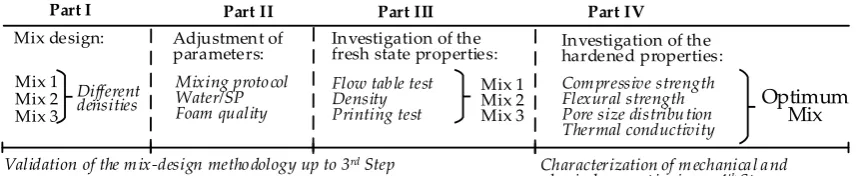
Based on the considerations mentioned regarding the performance of two existing surfactants, this study focuses on the pre-foaming production technique using a protein-based foaming agent. Figure 1 shows the structure of the experimental part of presented study. The study at hand is dedicated to achieving a printable foam concrete, which is stable and yields adequate rheological and mechanical properties suitable for 3D-printing. The constituent materials were chosen purposely to achieve sufficient green strength and later adequate mechanical properties for structural applications. Four recipes were prepared. The desired density of the fresh mixes was specified between 1100 kg/m³ and 1600 kg/m³. Finally, the insulating properties of the printable foam concrete were compared to those of normal-weight printable concrete (the reference material is described in [36]).
Part I Part II Part IV
Mix design: Adjustment of parameters:
Mixing proto col Water/SP Foam quality
Investigation of the fresh state properties:
Mix 1 Mix 2 Mix 3 Part III
Investigation of the hardened properties:
Com pressive strength Flexural strength Pore size distribu tion Thermal conductivity
Optimum Mix Flow table test
Density Printing test
Validation of the m ix-design metho dology up to 3rd Step Characterization of m echanica l a nd
physical pro pert ies i.a.w. 4th Step
Different densities
Mix 1 Mix 2 Mix 3
Figure 1. Overview of the experimental program.
2. Materials and methods
2.1 Mixture design methodology and experimental program
The scheme of the mixture design approach as developed in the framework of the research project CONPrint3D-Ultralight is presented in Figure 2. This approach can also be applied to the mixed foaming method. Then, foam characterisation is unneeded. The mixture design of a foam concrete using the pre-foaming method divides into two steps, namely establishing the cement-based matrix composition and determining the amount of foam to be added to achieve the desired density. In particular, the overall mixture design approach can be split into four steps, indeed as in Figure 2. Iterative optimisation is used to achieve satisfying printable foam concrete compositions.
Firstly, constraints such as range of water-to cement ratio (w/c) and cement content must be set according to the intended application. Based on information from the literature, suitable proportions and materials can be identified. Production and characterisation of the foam follow. The aim of this step is to obtain a sufficiently stable foam capable of withstanding the intermixing process. In parallel, water demand and binder composition of the cement-based matrix, including super-plasticiser (SP) dosage, are determined by iterative testing. In the first run, the goal of this procedure is to produce a cement-based matrix with minimal amounts of water, yet still sufficient to plasticise the matrix with the recommended dosage of SP. At the same time, the cement-based matrix must be flowable enough to ensure good incorporation of the foam into the mixture. An excessively stiff cement-based matrix leads to foam breakage or collapse, whereas an overly fluid matrix segregates. In this investigation the first estimation of water addition was done following a procedure described by Okamura and Ozawa [37]. As a result of the first step, there are a stable foam and an appropriately fluid cement-based matrix.
The last step specifies testing the hardened state properties of foam concrete, such as compressive and flexural strengths, thermal conductivity, and/or durability. At this stage, the water-to-binder ratio (w/b) may be reduced or reinforcement in the form of dispersed nano- or microfiber may be introduced [1,3,41].
1st Step
2nd Step
3rd Step
4th Step
1. Choice of target density and constrains for mix design
1.1 Foam 1.2 Cement-based matrix
2.1 Stable foam 2.2 Workable cement-based matrix 2. Foam concrete
production and characterisation
Water demand, SP, determination of binder Foam production and
characterisation
2.3 Stable foam concrete Decrease water/SP Increase water/SP Adjust mixing protocol Yes Yes No No No 3. Rheological characterisation Yes 3.1 Rheology adequancy No Adjust binder (thixotropy) Add accelelerator
Low buildabil ity
L ow f low abi li ty No Adjust foam parameters Yes
4. Mechanical characterisation
Hardened properties adequancy
No No
Yes
Printable foam concrete
Add reinforcement, e.g. nanofibers Change w/b No Adjust foam parameters
Figure 2. Mixture design approach for printable foam concrete.
2.2 Determination of the water demand
It is essential to specify a suitable water content in the foam concrete. There is no standard procedure, especially when the requirements of printability, pumpability and buildability must be fulfilled. In the present work the water demand of the cement-based matrix was determined by Okamura’s and Ozawa’s method [37]. The compositions of powders tested are listed in Table 1.
Table 1. Binder compositions tested following the Okamura procedure.
Binder Cement type Composition by volume [fly ash : cement]
Fly ash-to-cement ratio [by weight]
A-0 CEM II 0 : 100 0.00
A-1 CEM II 40 : 60 0.47
2.3 Raw materials
equalled 1050 kg/m3. A protein-based foaming agent (Oxal PLB6, MC-Bauchemie GmbH & Co. KG, Bottrop, Germany) was utilized for production of the foam.
Table 2. Chemical composition of cement and fly ash (LOI = loss on ignition).
Material Density [g/cm3] Chemical composition [% by mass]
Residue SiO2 Al2O3 Fe2O3 CaO MgO SO3 K2O Na2O LOI CO2 Cl
CEM II/A-M
(S-LL) 52.5 R 3.12 0.74 20.63 5.35 2.82 60.94 2.14 3.52 1.05 0.22 3.47 2.87 0.07
Fly ash H4 2.22 3.6 0.6 2.9 1.8 < 0.01
Figure 3. Particle size distribution of the solid constituents.
2.4 Mixing procedure
In a preliminary stage, three litres of the cement-based matrix paste were produced to assess the water demand using a pan mixer (Hobart NCM20, 5 L capacity). Table 3 describes the mixing procedure.
Table 3. Binder paste mixing procedure for the determination of the powders’ water demand.
Time
[min:sec] Speed [rpm] Action
0:00 0 Add water to the solids
0:00 – 1:00 2500 Mixing at low speed
1:00 – 1:30 5000 Mixing at high speed
1:30 – 3:00 0 Rest, over this time scrap the walls
3:00 – 4:00 5000 Mixing at high speed
Table 4. Foam concrete mixing procedure.
Time [min:sec] Speed [rpm] Action
0:00 0 Add water to the solids in mixing tank
0:00 – 2:00 3000 Mixing at high speed
2:00 – 2:30 0 Inspect the mixture for homogeneity 2:30 – 4:30 3000 Mixing at high speed
4:30 – 5:00 0 Adding of 40% of the whole foam volume
5:00 – 7:00 1500 Mixing the matrix and the foam together at slow speed 7:00 – 8:00 0 Adding further 40% of the whole foam volume
8:00 – 10:00 1500 Mixing the matrix and the foam together at slow speed 10:00 – 11:00 0 Adding the remaining 20% of the whole foam volume
0.040.06 0. 1
0.2 0.4 0.6 1 2 4 6 810 20 40 60 100 200 400 600 1000
0.0 0.4 0.8 1.2 1.6 2.0 2.4 2.8 3.2
Incre
men
tal vo
lu
me in
[
%]
Particle diameter in [mm]
CEM II / A-M(S-LL); Fly ash H4; Comulat. volume CEM II / A-M(S-LL); Comulat. volume Fly ash H4
0 20 40 60 80 100
Co
mul
ativ
e vo
lu
me in
[
11:00 – 13:00 1500 Mixing the matrix and the foam together at slow speed
Foam concrete was produced using a conical, multi-rotor colloidal mixer (KNIELE KKM30, Kniele GmbH, Bad Buchau, Germany). For each experiment 30 L of foam concrete were prepared using the procedure according to Table 4. After the binder matrix was mixed, the separately produced foam was added stepwise: 40%, then another 40% and finally the remaining 20% of the total foam volume.
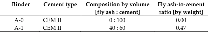
2.5 3D-printing process
Extrusion and deposition experiments were conducted using two devices: a) a standalone progressive cavity pump (PCP1) DURAPACT DP 326S, and b) the 3D-concrete-printing test device (3DPTD) equipped with PCP2; see Figure 4. In case “a” a 25 mm diameter pipe was used, while its nozzle outlet was positioned manually to deposit concrete layers. In case “b” the nozzle outlet is positioned autonomously with a pre-programmed Lua-script, a programming language. When using PCP1, the pumping flow rate was set to 10 L/min and the nozzle outlet had a round cross-section with a diameter of 20 mm. Printing experiments with custom-developed 3DPTD were performed with two different rectangular nozzle geometries of 10 mm by 50 mm and 20 mm by 30 mm to investigate the influence of this parameter on the printability performance of foam concrete. A printing speed of 40 mm/s was selected based on preliminary extrudability investigations. Straight wall specimens with a length of 700 mm were produced with layer-to-layer deposition time intervals of 30 s. To assess the buildability of a mixture composition, a maximum number of layers was deposited, one atop the other, until self-collapse occurred. Additionally, walls made of only three layers were printed and eventually used in the preparation of specimens for mechanical testing.
(a) (b)
Figure 4. (a) The standalone PCP, DUROPACT DP 326S, (b) 3D-conrete-printing test device (3DPTD).
2.6 Specimen preparation
Each printed wall was transferred to a climatic chamber at an age of 24 hours and cured at a constant temperature of 20 °C, at a relative humidity of 65%, and in absence of wind for 27 days. At the age of 6 days the walls were saw-cut to make specimens for mechanical testing. The sawing occurred without addition of water to avoid absorption; the specimens were then returned to the climate chamber. Cubes with an edge length of 40 mm were prepared for the compressive strength testing, whereas the dimensions of specimens for the bending tests varied in a range of 30 to 33 mm width and 50 to 56 mm height, which corresponds to that of three printed layers. Uneven sideward surfaces of the layers were not polished. The length of beam specimens was 160 mm. Loading area was even-tempered with fast setting gypsum.
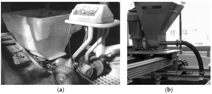
2.7 Mechanical testing
compressive strength measurements the loading plates of the test setup were 40 mm by 40 mm according to the cross-section of the cubes.
(a) (b)
Figure 5. Measurement of the mechanical properties of the printed specimens: (a) 3-point bending test, (b) uniaxial compression test.
2.8 Thermal conductivity measurements
Specimens of dimensions of 70 x 70 x 20 mm³ were saw-cut from the walls printed in the same manner as those for mechanical testing. The insulation properties of the optimum mix composition were measured with a Heat Transfer Analyser ISOMET 2104 (Applied Precision Ltd, Bratislava, Slovakia). This apparatus applies a dynamic measurement method which enables the reduction of the period of the thermal conductivity measurements to a mere 10 to 16 minutes.
2.9 Scanning electron microscopy and light microscopy
Scanning electron microscopy (SEM) was used to visualise the microstructure of the foam concrete. The SEM unit Quanta 250 FEG (Thermo Fisher Scientific, Waltham, MA/USA) was operated in the so-called “low-vacuum mode”, whereby the non-conductive specimens were imaged as-obtained without sputter-coating.
(a) (b) (c)
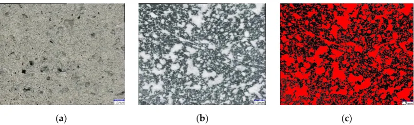
Figure 6. Typical initial image and sequence of processed images of foam concrete: (a) polished
specimen, (b) coloured image, (c) binary image processed for computational measurements of
air-voids parameters.
3. Results and discussion
3.1 Determination of water demand of the powders
The water demand 𝛽𝑝 was obtained for a pre-selected powder mixture by extrapolating relative
slump values Γp (Eq. 1) linearly from the measurements for various volumetric water-to-powder
ratios to the zero slump. At this state, the amount of water in the paste is assumed to be just enough to wet the surfaces of all particles and fill all the voids in the system (saturation point). Note that no admixtures are used in such a characteristic stage of the study.
Γ𝑝= [
(𝐷1+ 𝐷2) 2⁄
𝐷0
]
2
− 1, (1)
where 𝐷1and 𝐷2are the spread diameters obtained in slump flow test (measured in two directions),
and 𝐷0is the base diameter of the conical frustum used in the test (here: 100 mm).
Figure 7a shows all results of Γ𝑝 for composition A-0, including those smaller than 1, whereby
a non-linear relationship between water-to-powder ratio and Γ𝑝 can be seen for small values of the
latter. When all measurements of Γ𝑝 are considered, the resulting β𝑝 would be 1.13, which might
lead to a very low w/c and an insufficiency of water in the mixture. According to the existing guidelines [43,44] only the region Γ𝑝 > 1 is taken into to account for linear extrapolation to obtain β𝑝.
Figure 7b illustrates this case. The water demand β𝑝 obtained in this way for the compositions A-0
and A-1 equals 1.33 and 1.10, respectively.
(a) (b)
Figure 7. Results of relative slump values for the binder pastes: (a) all values for the composition A-0, (b) results obtained in the range Γp > 1 for the compositions A-0 and A-1.
The water demand of self-compacting concrete following Okamura’s procedure is usually set at 80 to 90 % of the experimentally determined βp value, with the transition from paste to mortar or
0.0 0.5 1.0 1.5 2.0 2.5 3.0
0.6 0.8 1.0 1.2 1.4 1.6 1.8 2.0
Relative slump flow Gp, Composition A-0
Linear polynominal fit, A-0
Wa te r-to -po wde r volu m e rat io [-]
Relative slump flow Gp [-]
y = 0.1984x+1.1311
0.0 0.5 1.0 1.5 2.0 2.5 3.0
0.6 0.8 1.0 1.2 1.4 1.6 1.8 2.0
Relative slump flow Gp, Composition A-0
Linear polynominal fit, A-0
Relative slump flow Gp, Composition A-1
Linear polynominal fit, A-1
Wa te r-po wde r volu m e rat io [-]
Relative slump flow Gp [-]
concrete. Various effects of the additional mineral ingredients in concrete as compared to the mortar are considered in the form of this scaling factor [43], but first of all it considers the effect of the superplasticisers (SP) added for the production of mortar and concrete, in contrast to the paste which was tested without addition of SP. In the present study such a reduction factor was introduced individually due to characteristics of the prefabricated foam. Taking into account the instability of the foam over time, e.g. 30 g water per litre foam drained in a time period of 35 min, and the observation that a certain volume of the foam collapses during intermixing into the cement paste, the experimentally determined value of βp was reduced by 25%.
3.2 Mixture design
For the first foam concrete experiments, composition A-1, consisting of cement and fly ash, was chosen. The foam volume was calculated according to the method described in [35], which does not take into account the amount of water in the foam, however, but regards only the water in the cement-based matrix. Contrarily, the w/c of foam concrete is in fact increased by the water content in the foam. Thus, in the study at hand the whole amounts of water both in the foam and in the HRWRA were subtracted from the total water content that had been determined by Okamura’s method. Three mixture compositions with different densities were designed; see Table 5.
Table 5. Mixture compositions of the foam concretes under investigation.
Mix-ture
Target density [kg/m3]
Matrix (w/c)eq
FC (w/c)eq
Cement [vol % of
FC]
Fly ash [vol % of
FC]
Water [vol % of FC]
SP [wt % of
binder]
Foam [vol % of
FC]
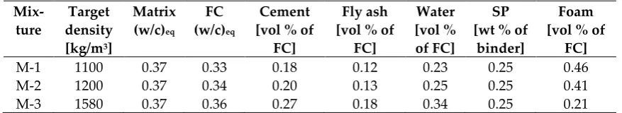
M-1 1100 0.37 0.33 0.18 0.12 0.23 0.25 0.46
M-2 1200 0.37 0.34 0.20 0.13 0.25 0.25 0.41
M-3 1580 0.37 0.36 0.27 0.18 0.34 0.25 0.21
3.3 Properties of foam concrete in its fresh state
3.3.1 Flow table test
Table 6 summarises the properties of the foam concrete mixtures. All three compositions exhibited similar spread values, which stem from the comparable proportions of constituents and similar water-to-binder ratios. Upon the addition of foam, the spread values after strokes did not change significantly. The differences in the density of the mixtures could be expected to influence spread values when considering related differences in gravitational forces. However, while the density increased from M-1 to M-2 to M-3, the content of the cement paste increased as well, hence leading to higher static yield stress and more pronounced structural build-up at early ages. The increase in yield stress seems to counteract the increase in gravitational force, so that all the tested mixtures had similar spread values.
Table 6. Foam concrete properties in the fresh state.
Mixture Matrix Foam concrete (FC)
Spread diameter Relative spread*
(matrix)
Spread diameter Rel. spread*
FC before
strokes [mm]
after strokes [mm]
before strokes [mm]
after strokes [mm]
M-1 103 122 0.18 102 126 0.24
M-2 103 120 0.17 107 132 0.23
M-3 105 121 0.15 105 133 0.27
*Relative spread = before strokes / after strokes – 1.
Figure 8. Flow spread of the cement-based matrix and the corresponding foam concrete composition M-2 before and after strokes.
3.3.2 Verification of the density
A common challenge in foam concrete production is the instability of its pore system and the resulting deviation from the targeted density, hereafter termed as density discrepancy. The risk of such discrepancy is increased in the case of printable foam concretes due to their relatively stiff cement-based matrix. Therefore, the mixture design approach of the study at hand incorporates a step for the revision of the concrete composition based on this discrepancy in the density achieved, as compared to the initial target density. Table 8 presents the results of the density measurements.
Mixture M-1 had an initial target density and a finally measured fresh mixture density of 1100 kg/m³ and 1180 kg/m³, respectively. Similarly, M-3 had a fresh density of 1430 kg/m³ which differed markedly from the target value of 1580 kg/m³. Interestingly the density discrepancy of M-2 was almost negligible in comparison to that of the other mixtures. Results presented in [35] indicate that instability of the foam concrete may be caused by a range of factors. Generally, any deviation from the target density can be attributed to stability of the foam (collapse/drainage), mixing time, mixing speed and the design of the mixer used. Prospective rheological and microstructural investigations should contribute to the remedy of the instability of the printable foam concrete observed in this study. It was clearly observed that the foam added could either increase its volume during the agitation, or partially collapse, both processes significantly altering the density.
Table 7. Overview of density characteristics of the foam concrete compositions under investigation.
Mixture Target fresh density [kg/m³]
Fresh density [kg/m³]
Deviation from designed density [%]
Dry density [kg/m³]
Drying weight loss [%]
M-1 1100 1180 + 6.78 970 17.8
M-2 1200 1197 - 0.25 980 18.1
M-3 1580 1430 - 10.5 1307 8.6
drying weight loss varied with the density; see Table 8. While the printable foam concrete composition with a fresh density of 1580 kg/m3 (M-3) had a weight loss upon drying of just about 9%, higher amounts of foam added gave rise to pronouncedly higher drying losses of approximately 18% (M-1 and M-2).
3.3.3 Extrudability and printing test
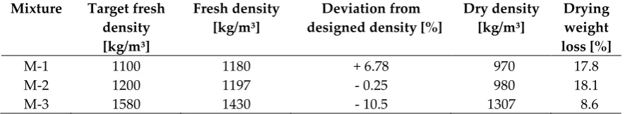
(a) (b)
(c)
Figure 9. Extrusion experiments with designed foam concrete: (a) composition M-1, extrusion witha standalone progressive cavity pump (PCP) DURAPACT DP 326S, (b) composition M-2 and (c) composition M-3, dispositioning with 3DPTD equipped with PCP.
All mixtures could be extruded and deposited during the first 20 minutes after production without any visible deformations upon deposition. During the preliminary investigation M-1 layers were extruded and deposited manually; see Figure 9a. Imperfections in the manual guidance of the extrusion nozzle made quantitative evaluation of the buildability of M-1 impossible. Despite this, the first trial extrusion of the designed foam concrete verified the appropriateness of the mix design approach for printable foam concrete as described in Section 3.1.
The buildability of the foam concretes M-2 and M-3 was evaluated by printing a maximum number of layers until collapse of the wall specimens. The maximum heights and number of layers of printed walls with M-2 and M-3 equalled 15 cm with 16 layers and 10 cm with 6 layers, respectively. Note that the geometries of the nozzles varied between M-2 and M-3, the aspect ratios (height to width) being 0.2 and 0.7, respectively. The edges of all layers retained the rectangular default shape imposed by the nozzle, and no significant deficiencies were noted on the surfaces of the deposited layers. In the observation period of 24 h after printing, no visible cracks or other signs for early age degradation were found.
Figure 10 shows the wall specimen of the composition M-2 with its discontinuities in the printed layers. This phenomenon was not observed for composition M-3, which had a higher density. It is worth noting that in comparison to mixture M-3 with an air content of 20 %, mixture M-2 had an air content of 40 %. This observation leads to the conclusion that the reduction of foam concrete density affected printing characteristics. Previous research on foam concrete rheology shows that with increasing air content, plastic viscosity also tends to increase. This underlines the role of the air content on the ability of foam concrete to flow under an applied shear stress [46]. In addition, due to higher air content and related lower gravitation force, the feed of material at the inlet of the extruder may not be continuous, which could also have led to the discontinuities in case of M-2.
Figure 10. Extruded wall samples. M1 was extruded manually.
3.4 Properties of foam concrete in the hardened state
3.4.1 Mechanical properties
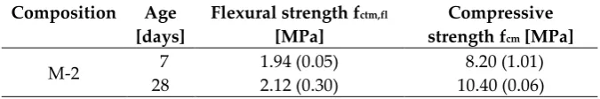
Table 8 presents the results of the compressive and bending tests on the hardened mixture M-2. The average values of the compressive and flexural strength of the printed foam concrete at an age of 28 days were 10.4 MPa and 2.12 MPa, respectively. Thus, they are perfectly in the range of the values reported in the respective literature on conventionally cast foam concretes that feature comparable densities [47,48]. Various projects had focused on enhancing the mechanical characteristics of foam concrete, pointing to possibilities of increasing its compressive strength. While some measures such as the use of nano-additives can enhance mechanical performance, it should be kept in mind that the compressive strength of foam concrete will remain strongly linked to its density. With density as the main factor influencing insulating characteristics, the set of hardened properties of foam concrete, i.e. its compressive strength and density, must be well specified, particularly in consideration of target applications.
Table 8. Average mechanical properties of foam concrete M-2; standard deviations are given in parentheses.
Composition Age [days]
Flexural strength fctm,fl
[MPa]
Compressive strength fcm [MPa]
M-2 7 1.94 (0.05) 8.20 (1.01)
28 2.12 (0.30) 10.40 (0.06)
3.4.2 Thermal conductivity
concretes; see also Section 4.4.3. Furthermore, the thermal conductivity of 3D-printed M-2 was similar to ordinary foam concrete with the same density reported in [30].
Table 9. Results of the thermal conductivity measurements; standard deviation is given in parenthesis.
Composition Average density [kg/m3]
Average value of λ [W/mK]
Source of the values
M-2 980 0.24 (0.02) study at hand
V-1 2100 1.68 (0.01) study at hand
Concrete 2240 1.70 [50]
3.4.3 Microstructure and porosity
Figure 11 shows exemplary and typical environmental scanning using an electron microscope (ESEM) images of the foam concrete M-2. The air bubbles have non-uniform geometry; their size is in the range of several tens to hundreds of micrometres; and they are separated by a cement-based matrix, i.e. they form no continuous network; see Figure 11a. Jones et al. [32] suggested for foam concrete in general that spherical bubbles occurred due to entrapped air and non-spherical bubbles were induced by the surfactant that created the foam.
(a)
(b) (c)
Figure 11. SEM pictures of the foam concrete M-2: (a) distribution and structure of pores, (b) matrix A-1 used for production of M-2, (c) segment of the wall between pores.
products densifying the matrix further. It may be concluded that neither the density of the microstructure nor the hydration characteristics of the fly ash were significantly influenced by foam addition or the 3D-printing process.
The walls between the air voids constitute the load-carrying frame in the structure of the foam concrete. Figure 11c shows that these walls feature numerous very small, nearly spherical voids, some of which are located at the interface to the foam bubbles. Hence, the surfaces of the characteristic foam voids are not smooth. However, a dense matrix structure in conjunction with isolated large air voids, which stem from the foam added, are prerequisites for high thermal insulation capacity, high compressive strength, and relatively low permeability of the foam concrete. Lastly, the very tiny voids that make the foam concrete interface non-coherent may impair the physical and mechanical properties of the hardened material. Further research is needed to be able to state the chemical reasons for the formation of these very little voids in the matrix and, as a next step, to avoid them.
Interestingly, no cracks originated or terminated at the large-scale air bubbles that stem from the foam. This finding indicates that local tensile strains due to different drying shrinkage degrees were insignificant, which is in contrast to [32].
Figure 12. Air-voids size distribution in the foam concrete M-2.
Figure 12 presents the air-void size distribution in the range of the deliberately introduced foam pores. The measured total porosity is 25.03%, 90% of all pores having a diameter smaller than 0.5 mm. The portion of the pores between 0.5 and 1 mm in diameter is 7% only, while pores greater than 1 mm make only 3% of the total number of pores. These findings obtained by digital light microscopy are in line with the more local observations by ESEM; see Figure 11.
4. Conclusions
Potential application of foam concrete in digital construction was reviewed and the mixture design for this novel material was developed and verified. The major findings of this work are as follows:
Based on an established approach to the mixture design of self-compacting concrete, it was possible to manufacture 3D-printable foam concretes in the density rage of 970 to 1500 kg/m3. These concretes could be extruded and deposited layer-wise.
The discrepancy between the designed target density and that achieved was in the range of 0.25% to 10%. Improvement in the stability of prefabricated foam, especially reduction of time-dependent drainage of water, should contribute to even more robust compositions in consecutive research steps.
The water-to-powder ratio of 0.37 of cement-fly ash paste in a proportion of 60:40 by volume with the addition of 0.25% of the SP by weight yielded an eminently workable cement-based matrix which is appropriate for the intermixing of prefabricated foam with minimal brakeage of bubbles.
0-0.5 0.5-1 1-1.5 1.5-2 2-2.5 >2.5
0 15 30 45 60 75 90
Fr
e
q
u
e
n
cy
in
[
%]
Air-voids diameter in [mm]
Frequency
Comulative frequency
90 92 94 96 98 100
Co
mu
la
tive
f
re
q
u
e
n
cy in
[
Foam concrete composition M-2, with a dry density of 980 kg/m3, exhibited a compressive strength of 10.4 MPa after 28 days. This indicates that printable foam concrete can be used for structural applications and may be applied for the construction of load-bearing walls in multiple-storey houses. From a broader perspective, walls with high thermal insulation (currently 0.24 W/mK) could be produced using additive technology directly on the site.
Future work should focus on rheological behaviour by varying foam contents and quantitative characterisation of the possible anisotropy of the mechanical properties of printed foam concrete. Production techniques for continuous foam concrete production, including the mixed foaming method, should be considered as well. It is expected to achieve raw densities of printable foam concrete in the range of 800-900 kg/m3 with appropriate mechanical characteristics for structural applications.
Acknowledgments: The authors express their sincere gratitude to the German Federal Ministry for the Environment, Nature Conservation, Building, and Nuclear Safety (BMUB) for funding this project in the framework of the research initiative Zukunft Bau of the Federal Institute for Research on Building, Urban Affairs and Spatial Development (BBSR). We also thank our industrial partners OPTERRA Zement GmbH, MC-Bauchemie Müller GmbH & Co. KG, Kniele GmbH, and BAM Deutschland AG.
References
1. Ramamurthy, K.; Kunhanandan Nambiar, E.K.; Indu Siva Ranjani, G. A classification of studies on properties of foam concrete. Cement and Concrete Composites 2009, 31, 388–396, doi:10.1016/j.cemconcomp.2009.04.006.
2. Jones, M.R.; McCarthy, A. Preliminary views on the potential of foamed concrete as a structural material. Magazine of Concrete Research 2005, 57, 21–31,
doi:10.1680/macr.57.1.21.57866.
3. Gilka-Bötzow, A. Stabilität von ultraleichten Schaumbetonen. Werkstoffe im
Bauwesen|Construction and Building Materials; Springer Fachmedien Wiesbaden: Wiesbaden, 2016.
4. Kearsley, E.P. Just Foamed Concrete - An Overview. Specialist Techniques and Materials for Concrete Construction; Thomas Telford Publishing, 1999; pp 227–237, ISBN 0-7277-4942-0. 5. Hajimohammadi, A.; Ngo, T.; Mendis, P. Enhancing the strength of pre-made foams for foam
concrete applications. Cement and Concrete Composites 2018, 87, 164–171, doi:10.1016/j.cemconcomp.2017.12.014.
6. Le, T.T.; Austin, S.A.; Lim, S.; Buswell, R.A.; Gibb, A.G.F.; Thorpe, T. Mix design and fresh properties for high-performance printing concrete. Mater Struct 2012, 45, 1221–1232, doi:10.1617/s11527-012-9828-z.
7. Schutter, G. de; Lesage, K.; Mechtcherine, V.; Nerella, V.N.; Habert, G.; Agusti-Juan, I. Test Vision of 3D printing with concrete — Technical, economic and environmental potentials. Cement and Concrete Research 2018, 112, 25–36, doi:10.1016/j.cemconres.2018.06.001.
8. Nerella, V.N.; Mechtcherine, V. 3D-Printing Technology for on-site Construction. CPI-Concr. Plant Int. 2016, 36–41.
9. Nerella, V.N.; Krause, M.; Näther, M.; Mechtcherine, V. Studying printability of fresh concrete for formwork free Concrete on-site 3D Printing technology (CONPrint3D). Conf. Rheol. Build. Mater.
10. Lublasser, E.; Adams, T.; Vollpracht, A.; Brell-Cokcan, S. Robotic application of foam concrete onto bare wall elements - Analysis, concept and robotic experiments. Automation in
Construction 2018, 89, 299–306, doi:10.1016/j.autcon.2018.02.005.
Preliminary Views on Its Potential Application in 3D Printed Multilayer Insulating Panels. 1st International Conference on Concrete and Digital Fabrication 2019, 19, doi:10.1007/978-3-319-99519-9.
12. Falliano, D.; Domenico, D.D.; Ricciardi, G.; Gugliandolo, E. Mechanical Characterization of Extrudable Foamed Concrete: An Experimental Study. Engineering and Technology International Journal of Civil and Environmental Engineering, 2018.
13. Buswell, R.A.; Leal de Silva, W.R.; Jones, S.Z.; Dirrenberger, J. 3D printing using concrete extrusion: A roadmap for research. Cement and Concrete Research 2018, 112, 37–49,
doi:10.1016/j.cemconres.2018.05.006.
14. Li, Z.; Wang, L.; Ma, G. Method for the Enhancement of Buildability and Bending Resistance of 3D Printable Tailing Mortar. Int J Concr Struct Mater 2018, 12, 677, doi:10.1186/s40069-018-0269-0.
15. Schowalter, W.R.; Christensen, G. Toward a rationalization of the slump test for fresh concrete: Comparisons of calculations and experiments. Journal of Rheology 1998, 42, 865–870,
doi:10.1122/1.550905.
16. Weng, Y.; Li, M.; Tan, M.J.; Qian, S. Design 3D printing cementitious materials via Fuller Thompson theory and Marson-Percy model. Construction and Building Materials 2018, 163, 600– 610, doi:10.1016/j.conbuildmat.2017.12.112.
17. Wangler, T.; Lloret, E.; Reiter, L.; Hack, N.; Gramazio, F.; Kohler, M.; Bernhard, M.;
Dillenburger, B.; Buchli, J.; Roussel, N.; et al. Digital Concrete: Opportunities and Challenges. RILEM Tech Lett 2016, 1, 67, doi:10.21809/rilemtechlett.2016.16.
18. Bos, F.; Wolfs, R.; Ahmed, Z.; Salet, T. Additive manufacturing of concrete in construction: Potentials and challenges of 3D concrete printing. Virtual and Physical Prototyping 2016, 11, 209– 225, doi:10.1080/17452759.2016.1209867.
19. Tay, Y.W.D.; Panda, B.; Paul, S.C.; Noor Mohamed, N.A.; Tan, M.J.; Leong, K.F. 3D printing trends in building and construction industry: A review. Virtual and Physical Prototyping 2017, 12, 261–276, doi:10.1080/17452759.2017.1326724.
20. Salet, T.A.M.; Bos, F.P.; Wolfs, R.J.M.; Ahmed, Z.Y. 3D concrete printing - a structural engineering perspective; Springer International Publishing: Cham, 2018.
21. Nambiar, E.K.; Ramamurthy, K. Influence of filler type on the properties of foam concrete. Cement and Concrete Composites 2006, 28, 475–480, doi:10.1016/j.cemconcomp.2005.12.001. 22. Al Jassmi, H.; Al Najjar, F.; Mourad, A.-H.I. Large-Scale 3D Printing: The Way Forward. IOP
Conf. Ser.: Mater. Sci. Eng. 2018, 324, 12088, doi:10.1088/1757-899X/324/1/012088.
23. Sarhya Narayanan, J.; Ramamurthy, K. Identification of set-accelerator for enhancing the productivity of foam concrete block manufacture. Construction and Building Materials 2012, 37, 144–152, doi:10.1016/j.conbuildmat.2012.07.025.
24. Khalil, N.; Aouad, G.; El Cheikh, K.; Rémond, S. Use of calcium sulfoaluminate cements for setting control of 3D-printing mortars. Construction and Building Materials 2017, 157, 382–391, doi:10.1016/j.conbuildmat.2017.09.109.
25. Soltan, D.G.; Li, V.C. A self-reinforced cementitious composite for building-scale 3D printing. Cement and Concrete Composites 2018, 90, 1–13, doi:10.1016/j.cemconcomp.2018.03.017.
26. Chen, X.; Yan, Y.; Liu, Y.; Hu, Z. Utilization of circulating fluidized bed fly ash for the preparation of foam concrete. Construction and Building Materials 2014, 54, 137–146, doi:10.1016/j.conbuildmat.2013.12.020.
27. Panda, B.; Paul, S.C.; Hui, L.J.; Tay, Y.W.D.; Tan, M.J. Additive manufacturing of geopolymer for sustainable built environment. Journal of Cleaner Production 2017, 167, 281–288,
doi:10.1016/j.jclepro.2017.08.165.
28. Nerella, V.N.; Markin, V.; Hempel, S.; Mechtcherine, V. Characterising bond between concrete layers resulting of extrusion-based digital construction. 1st International Conference on Concrete and Digital Fabrication, Digital Concrete 2018 – Zurich, Switzerland 2018, 115.
Concrete and Digital Fabrication – Digital Concrete 2018, 217–224, doi:10.1007/978-3-319-99519-9_20.
30. Neville, A.M.; Brooks, J.J. Concrete Technology; Pearson Education Limited, 2008.
31. Holt, E.; Raivio, P. Use of gasification residues in aerated autoclaved concrete. Cement and Concrete Research 2005, 35, 796–802, doi:10.1016/j.cemconres.2004.05.005.
32. Jones, M.R.; Ozlutas, K.; Zheng, L. High-volume, ultra-low-density fly ash foamed concrete. Magazine of Concrete Research 2017, 69, 1146–1156, doi:10.1680/jmacr.17.00063.
33. Jones, M.; Zheng, L.; Mohammad, M. Bubble Structure, Stability and Rheology of Foamed Concrete.
34. Aldridge, D. Introduction to foamed concrete: what, why, how? Propump Engineering Ltd. ICE Publishing 2016.
35. Mohammad, M. Development of foamed concrete enabling and supporting design. PhD thesis, University of Dundee, Scottland, 2011.
36. Nerella, V.N.; Hempel, S.; Mechtcherine V. Micro-and macroscopic investigations on the interface between layers of 3D-printed cementitious elements. International Conference on Advances in Construction Materials and Systems 2017, 557–565.
37. Okamura, H.; Ozawa, K. Mix Design Method for Self-Compactable Concrete. Doboku Gakkai Ronbunshu 1994, 1–8, doi:10.2208/jscej.1994.496_1.
38. Roussel, N. Rheological requirements for printable concretes. Cement and Concrete Research 2018, 112, 76–85, doi:10.1016/j.cemconres.2018.04.005.
39. Perrot, A.; Rangeard, D.; Pierre, A. Structural built-up of cement-based materials used for 3D-printing extrusion techniques. Mater Struct 2016, 49, 1213–1220, doi:10.1617/s11527-015-0571-0. 40. Nerella, V.N.; Beigh, M.A.B.; Fataei, S.; Mechtcherine, V. Strain-based approach for measuring structural build-up of cement pastes in the context of digital construction. Cement and Concrete Research 2018, 115, 530–544, doi:10.1016/j.cemconres.2018.08.003.
41. Krämer, C.; Trettin, R.H.F. Investigations of nanostructured three-phase-foams and their application in foam concretes – a summary. Advanced Materials Letters 2017, 8 (11), 1072–1079, doi:10.5185/amlett.2017.1593.
42. Deutsches Institut für Normung e.V. DIN EN 480-11:2005-12, Zusatzmittel für Beton, Mörtel und Einpressmörtel_- Prüfverfahren_- Teil_11: Bestimmung von Luftporenkennwerten in Festbeton; Deutsche Fassung EN_480-11:2005; Beuth Verlag GmbH: Berlin, 2005.
43. Brameshuber, W. Selbstverdichtender Beton; Bau und Technik: Düsseldorf, 2004, ISBN 3-7640-0417-7.
44. Okamura, H.; Ouchi, M. Self-Compacting Concrete. Journal of Advanced Concrete Technology 2003, 5–15, doi:10.3151/jact.1.5.
45. M. Näther, V. N. Nerella, M. Krause, G. Kunze, V. Mechtcheirine, R. Schach. Beton-3D-Druck – Machbarkeitsuntersuchungen zu kontinuierlichen und schalungsfreien Bauverfahren durch 3D-Formung von Frischbeton; Ffraunhofer IRB Verlag, Fraunhofer-Informationszentrum Raum und Bau, 2017, ISBN 978-3-7388-0028-9.
46. Bagheri, A.; Samea, A. Effect of air content on rheology of foamed concrete. Magazine of Concrete Research 2018, 1–29, doi:10.1680/jmacr.17.00267.
47. Bing, C.; Zhen, W.; Ning, L. Experimental Research on Properties of High-Strength Foamed Concrete. J. Mater. Civ. Eng. 2012, 24, 113–118, doi:10.1061/(ASCE)MT.1943-5533.0000353. 48. Yang, K.-H.; Lee, K.-H. Tests on high-performance aerated concrete with a lower density.
Construction and Building Materials 2015, 74, 109–117, doi:10.1016/j.conbuildmat.2014.10.030. 49. Nerella, V.N.; Näther, M.; Iqbal, A.; Butler, M.; Mechtcherine, V. Inline quantification of
extrudability of cementitious materials for digital construction. Cement and Concrete Composites 2019, 95, 260–270, doi:10.1016/j.cemconcomp.2018.09.015.