14 |
P a g e
3-PHASE MOTOR ON-OFF CONTROLUSING
MOBILE WITH FEEDBACK
Prof.Somanath M. Lambe
1, Ms.Nagma M.Mulla
2, Ms.Aishwarya V.More
3,
Ms.Shweta S. Gharpure
4, Ms.Poonam P.Kadam
51,2,3,4,5
Dept.of Electronics & Telecommunication,
Karmayogi Engineering college shelve-Pandharpur (India)
ABSTRACT
Nowadays, the increasing role of advanced electronic Systems, Mobile networks, wireless communications and
digital technologies affects many methods used in remotely controlled Systems. One of these methods is the
mobile –based control system design and analysis, which is practical and applicable in read-time development.
This paper suggests a new remote control technique based on mobile capabilities to control a driving motor
circuit which in turn will monitor and control the 3-phase ac motor. The proposed system can generate a
control signal through a Global system for mobile communications (GSM) modem by Dual Tone
Multi-Frequencies (DTMF) techniques to drive the ac motor .The system is more efficient for the farmers to access the
motor without any extra efforts by using mobile. An experimental study was done and the obtained result
showed the effectiveness of the proposed method.
Keywords: Mobile, DTMF Decoder, 3-Phase Motor
I.
INTRODUCTION
The main earning source of 75% of Indian population is nothing but the agriculture so,the main focus of this
paper is to show how to monitor and regulate the control of a ac-motor remotely using mobile techniques. The
actuality of the use of mobile in tele-remote system was inspired by many factors:
• The Huge number of people that use mobile phones in their daily lives. • The low cost of mobile communication.
• The existing infrastructure that supports mobile communication across the globe (such as GSM). • The experimental results verify that the DTMF control drive system is highly effective,reliable,proper
and applicable to achieve remote control of motor.
II.SURVEY
The use of DTMF Signals instead of Radio Frequencies (RF) signals. These Factors encouraged many
researchers to work in this area, for example the problem of implementing of home automation system were
considered by (Delgado,et,al.,2006) and (Ciubotaru,et al.,2006) who presented designs and implementations of
15 |
P a g e
based on DTMF signals such as D.Manoj Kumar that considered in his work industrial applications .Inadditions, shatnawi and his group were interested in such a problem in their work “ Digital Reciever for DTMF
signals,(Mghawish,et al.,2012), and also related research work was done by Callahan in his article “Integrated
DTMF receiver(Callahan,1979).
II.
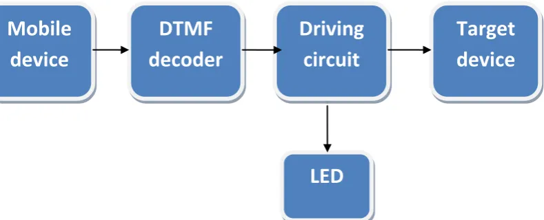
THE BLOCK DIAGRAM FOR THE PROPOSED WORK SYSTEM
The Proposed system was done to serve remote control of a 3-phase ac motor and DTMF signals based on
GSM modem, DTMF decoder. Driving circuit, and other required electronics such as (transistors, resistors,
LEDs, etc…..) as shown in the figure1 below
Figure 1. A Block Diagram for the Remote Control System
The mechanism of the system consists of following aspects:
The aspect uses the DTMF model to generate the call signal that will be served later after its processing as
tele-control signal for electronic appliance .
Ashort Description of some devices used in the system.
A mobile phone is used to send the DTMF code from a user (remote location) to the control system
regardless of time and space.
A DTMF decoder decodes the signals and sends them to Driving system.
A driving system consists of relays, transistors, resistors, LEDs, and other required electronics. The driving
system gets signals from DTMF and directs them to regulate the 3-phase motor.
III. DTMF
DTMF is a system of signal tones used in telecommunications. There are twelve standard signals and four extra
buttons “A”, “B”, “C”, “D”, which normally are unseen on telephone keypad. Each signal is comprised from two tones “low” and” high” as shown in this table:
Mobile
device
DTMF
decoder
Driving
circuit
Target
device
16 |
P a g e
Table 1. The frequencies used for each DTMF signal.
When a button is pressed on a keypad, a connection is made that generates two tones at the same time. These
two tones identify the pressed key to controlled device
The calculation of the frequency for each keypad button is performed by adding the frequencies of a row and a
column for every corresponding button.
For example, in order to generate the DTMF tone for "1", you mix a pure 697 Hz signal with a pure 1209 Hz signal, like so:
+ =
697 Hz Sine Wave
+ 1209 Hz Sine Wave = DTMF Tone "1"
.wav, .au .wav, .au .wav, .au
Figure 2. Two Pure Sine Waves combine for form the DTMF Tone for "1" and so on.
The use of four extra buttons “A” “B” C D” is to prevent to control remote device.
The calculation of frequencies of all characters placed on the keypad of the mobile phone is
summarized in this table:
Table 2. The high and low frequencies for each key of the keypad
Number
High Frequency
Low Frequency
BCD
1
1209
697
00000001
2
1336
697
00000010
3
1477
697
00000011
A
1633
697
00010000
4
1209
770
00000100
1209Hz 1336Hz 1477Hz 1633Hz
697 Hz
1
2
3
A
770Hz
4
5
6
B
852Hz
7
8
9
C
17 |
P a g e
5
1336
770
00000101
6
1477
770
B
1633
770
00010001
7
1209
852
8
1336
852
00001000
9
1477
852
00001001
C
1633
852
00010010
*
1209
941
0
1336
941
00000000
#
1477
941
D
1633
941
IV REMOTE CONTROL SYSTEM METHODOLOGY
In this paper a remote control system is developed to perform controlling actions using a mobile phone. The
proposed system can receive DTMF signals and sends them via DTMF decoder to a driving system that in turns
will control the target device (Xuehua C.P,2008).
The DTMF signal are sent from the user – mobile phone to a GSM modem with a DTMF decoder connected to
the main circuit of the controller an shown in figure2:
Mobile
device DTMF Decoder
Driving Circuit
LED
Target device dtmf
The DTMF signal is generated when the keypad button is pushed by the user – mobile phone, then this signal is
decoded to Binary Decimal Digits (BCD) by the DTMF decoder, after that the BCD is sent to microcontroller
(Sharma K.,et al.,2006).
The following steps describes how the proposed system operates:
1. The user sends DTMF tone to the GSM through the DTMF decoder.
18 |
P a g e
3. These signals will send to the driving system that contained the relays, which must regulate the switching ofmotor.
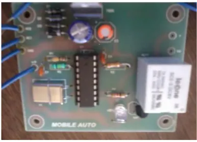
V THE EXPERIMENTAL PART
The general kit of the implemented circuit, which has been used to test a practical developed remote controlled
system( Mghawish,et al.,2012), is shown in the figure.3 below :
Figure 4. Testing circuit.
The main hardware parts using in designing the proposed system are as follows
• Power supply. • DTMF decoder.
• Light Emitting Diodes (LEDs).
VI MAIN IMPLEMENTING PROCEDURE
The implementation part of the proposed system has been done following the below procedure
Analyzing and testing the sending and receiving processes for DTMF signals to ensure their
correctness.
The verifying of DTMF signals has been done by repeatedly generating sample signal tones for some
keypad buttons and testing the output of the DTMF decoder to ensure that the obtained signals are
decoded to BCD format. This is done by verifying the DTMF decoder:
The DTMF decoder receives the decoded DTMF signal and converts them to desired form for use to
19 |
P a g e
The results obtained by the experimental study are summarized in the following table:DTMF Action to be performed by driving circuit
Pressed key
BCD
‘1’ 00000001 Motor rotation „counter
clockwise within specific units of time‟
‘2’ 00000010 Motor rotation „clockwise within
specific units of time‟
‘3’ 00000011 A motor driver drops
‘4’ 00000100 LEDs will glow
‘5’ 00000101 LEDs stop glowing
‘6’ 00000110 Whole system drops
Table3. Results of experimental study
The sending the DTMF signals will be control the motor ON-OFF. so, as to access the motor by user from
anywhere by using mobile with feedback.
VII CONCLUSION
The proposed paper demonstrates the remotely controlled system based on mobile phone device which can
operate using the following method: DTMF coded signals to affect the driving system for controlling ON-OFF
of a 3-phase motor.
The main advantages of the proposed system are its reliability, low cost, and wide area using.
REFERENCES
:
[1] Alkar, A. Z., & Buhur, U. (2005). An Internet Based Wireless Home Automation System for
Multifunctional Devices. IEEE Consumer Electronics, 51(4), 1169-1174.
[2] M J. Callahan, Jr., “Integrated DTMF receiver,” ZEEE J. Solzd-State Czrcuzts, vol.,1 Sc-14, pp. 85-90,
Feb. 1979.
[3] Ciubotaru-Petrescu, B., Chiciudean, D., Cioarga, R., & Stanescu, D. (2006). Wireless Solutions for
Telemetry in Civil Equipment and Infrastructure Monitoring. 3rd Romanian-Hungarian Joint
Symposium on Applied Computational Intelligence (SACI) May 25-26, 2006.
[4] Delgado, A. R., Picking, R., & Grout, V. (2006) Remote-controlled home automation systems with
different network technologies. Proceedings of the 6th International Network Conference (INC 2006),
University of Plymouth, 11-14 July 2006, pp. 357-366.
[5] Afif Mghawish, Akram A. AbdelQader, Mahmoud A. Al-Jezawi, Mohammad AbuMahfouz. Multi
Function Control System using GSM modem Based SM5100B Module. ICITST-2012 London,
Technical Co-Sponsored by IEEE UK/RI Computer.
[6] Murthy, M. V. R. (2008). Mobile based primary health care system for rural India. W3C workshop on
20 |
P a g e
[7] R.Sharma, K. Kumar, and S. Viq, “DTMF Based Remote Control System,” IEEE InternationalConference ICIT 2006, pp. 2380-2383, December 2006. Suvad Selman, Raveendran Paramesran
“Comparative Analysis of Methods Used in the Design of DTMF Tone Detectors”, IEEE International
Conference on Telecommunications and Malaysia International Conference on Communications, 14-17
May 2007.
[8] Chen Peijiang Xuehua, “Design and Implementation of Remote Monitoring System Based on GSM”,
2008 IEEE Pacific-Asia Workshop on Computational Intelligence and Industrial Application.
[9] Yun Chan Cho and Jae Wook Jeon “Remote Robot control System based on DTMF of Mobile Phone”,