PFM Analysis of Embedded Crack in RPV
Y. Kanto1 ) and G. Yagawa2 )
1) Department of Mechanical Engineering, Toyohashi University of Technology 2) Department of Quantum Engineering and Systems Science, University of Tokyo
ABSTRACT
This paper describes a probabilistic fracture mechanics (PFM) analysis of aged nuclear reactor pressure vessel (RPV) material. PFM approach is regarded as an appropriate method in rationally evaluating plant life and in risk-based decision making such as risk-informed inspection, since it can consider various uncertainties such as sizes and distributions of cracks, degradation of material strength due to aging effects, fluctuating loading histories, accuracy and frequency of pre- and in-service inspections. Thus, various PFM computer programs have been developed and applied in practical situations in the last two decades. But the most programs can calculate only for surface cracks, because of the difficulty of evaluating fracture parameters for embedded cracks, and the cost of computation.
A new simulation program has been developed to solve PFM analysis of RPV with both elliptical embedded cracks and semi-elliptical surface cracks. To demonstrate the effectiveness of the program, one of PFM round-robin problems set by JSME-RC111 committee, i.e. "aged RPV under normal and upset operating conditions" was solved. The effect of ignorance of embedded cracks is also examined, and the availability of usual PFM codes, which ignore embedded cracks, is discussed.
INTRODUCTION
Probabilistic Fracture Mechanics (PFM) has become an important tool [1, 2]. The PFM approach is regarded as an appropriate method in rationally evaluating plant life and in risk-based decision making such as risk-informed inspection [3] since it can consider various uncertainties such as sizes and distributions of cracks, degradation of material strength due to aging effects, fluctuating loading histories, accuracy and frequency of pre- and in-service inspections. Thus, various PFM computer programs have been developed and applied in practical situations in the last two decades.
In those analyses, semi-elliptical surface cracks are usually assumed as initial cracks for the purpose of convenience. However, as well known, embedded cracks seem more practical and probable as initial cracks. Thus as one of main tasks in the JWES-PFM subcommittee[4], we are developing a new PFM model considering transition from embedded to surface cracks during crack growth. In the previous work[5], Monte Carlo simulation was carried out considering embedded crack distributions. But the computational costs increased extremely for embedded crack calculations, because the number of probabilistic variables increases in that case. Here, a new PFM program was developed, which evaluate failure probability by using integration method[6] proposed by JSME-PFM research committee instead of Monte Carlo simulation. To investigate the precision of the method and effects of transition from embedded cracks to surface cracks in PFM analyses, one of PFM round-robin problems set by JSME-PFM research committee[6], i.e. “aged RPV under normal and upset operating conditions” is solved.
DEVELOPMENT OF PFM PROGRAM
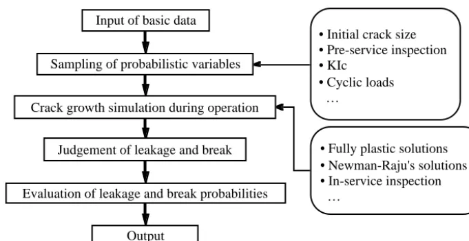
Figure 1 illustrates the flow of a typical PFM analysis. First, some probabilistic variables are selected according to an analysis model employed. Probabilistic variables to be considered here were initial crack sizes (crack depth and crack aspect
SMiRT 16, Washington DC, August 2001 Paper # 1608
ratio) and location. Next, crack growth simulations are performed. Fracture mechanics model employed here was based on the linear elastic fracture mechanics, such as Newman-Raju's solutions [7]. During crack growth simulation, PSI and ISI may be considered, and failure judgments of leakage and break are performed. Cumulative failure probabilities are calculated as functions of operation time. To calculate accurate failure probabilities effectively, the Stratified sampling Monte Carlo (SMC) algorithm is often employed. For embedded crack calculations, however, more efficient procedure should be used because of high computational cost. Here we used the integration method proposed by JSME-PFM research committee[6].
Input of basic data
Sampling of probabilistic variables
Crack growth simulation during operation
Judgement of leakage and break
Evaluation of leakage and break probabilities
Output
• Initial crack size • Pre-service inspection • KIc
• Cyclic loads …
• Fully plastic solutions • Newman-Raju's solutions • In-service inspection …
Fig. 1 Flow of PFM analysis
Before revising the old program to the new one, the program was totally redesigned by using object oriented design approach and the design pattern approach[8]. The result was shown in Fig. 2. Although all functions in the figure was not implemented yet in the current program, the extension will be very easy because of OO approach.
ANALYSIS PROBLEM
A PFM model analyzed here is basically the same as the PFM round-robin problem for an aged RPV under normal and upset operating condition, which was given by JSME-RC111 committee [6] except consideration of embedded cracks.
Analysis Models
RPV can be simply simulated by a cylinder with an axial embedded elliptical crack. But here it is simplified furthermore to a plate with a embedded crack. The embedded elliptical crack may be converted to the semi-elliptical surface crack, according to a certain conversion criterion as described later. In both models, plate thickness and width are taken to be t = 0.2 m and 2b = 12.6 m, considering the belt line portion of PWR pressure vessels. The plates are assumed to be subjected to various magnitudes of remote uniform tensile and bending stresses. For the purpose of simplicity, we ignore curvature effects of actual pressure vessels in evaluating 3-dimensional SIFs. Cumulative failure probabilities of one existing crack, whose unit is 1/crack, are calculated as functions of operation years.
Initial Crack Distribution
Because we do not have any available data for embedded crack distributions, we use the Marshall distribution[7], which was obtained as surface flaw distribution, for the length of the elliptical crack in the thickness direction 2a2, and a log-normal
AxialCrack Bending Load stress getStress Membrane Material toughness crackGrowthRate DeterministicVariable value Distribution ProbabilisticVariable aDistribution Input Data
• Probabilistic variables • Distributions • Fatigue Loads • Estimation Loads • Model
• Time integration algorithm • Space integration algorithm
Space Integration
P F M
input run Singleton Pattern Iterator Pattern Flyweight Pattern all all all Space pvList noPV createNode integration Iterator Pattern FatigueLoadSet n list nodes
How to use variables
Bridge Pattern HoopCrack form FatigueLoad maxMembrane minMembrane maxBending minBending frequency getDeltaMembrane getDeltaBending Crack Plate thickness width length Buried depth width location Surface depth width Infinite depth CrackForm N o d e
aModel aMaterial aFatigueLoadSet variableSpace Variable name Model
P i p e
thickness radius length all all all 1 1 1 1 1 1 1 AxialCrack Bending Load stress getStress Membrane Material toughness crackGrowthRate DeterministicVariable value Distribution ProbabilisticVariable aDistribution Input Data
• Probabilistic variables • Distributions • Fatigue Loads • Estimation Loads • Model
• Time integration algorithm • Space integration algorithm
Space Integration
P F M
input run Singleton Pattern Iterator Pattern Flyweight Pattern all all all Space pvList noPV createNode integration Iterator Pattern FatigueLoadSet n list nodes
How to use variables
Bridge Pattern HoopCrack form FatigueLoad maxMembrane minMembrane maxBending minBending frequency getDeltaMembrane getDeltaBending Crack Plate thickness width length Buried depth width location Surface depth width Infinite depth CrackForm N o d e
aModel aMaterial aFatigueLoadSet variableSpace Variable name Model
P i p e
distribution [9] for the crack aspect ratio (β = a1/a2), where a1 is the half length of the elliptical crack in the width direction, as follows:
(1)
(2)
where α = 1.035, βm = 1.336, γ = 0.5382, µ = 3.124 x 10- 3 m and t = 0.2 m. The location or depth of the embedded crack, e, is another probabilistic variable and assumed to be uniformly distributed.
For a comparison, we calculated PFM analysis with a semi-elliptical surface crack. We use the same equations to Eqs. (1) and (2), but the variables are a for Eq.(3) and β = a/c for Eq.(4), respectively. The average size of surface crack is 6.248 × 10- 3 m.
Applied Loads
Nineteen kinds of cyclic tensile and bending stresses are chosen [6] from the design loading conditions of Level A (normal operation condition) and Level B (upset condition) which occur in the belt line portion of PWR pressure vessels listed in the Marshall report [7].
Failure Criteria
The failure modes considered here are leakage and break, whose criteria are simply defined as follows:
Break criterion: (3)
Leakage criterion: (4)
where is taken to be the largest K value along crack front, and is 135.0 MPa√m as the fracture toughness at 300˚C.
Fatigue Crack Growth
Only fatigue crack growth based on the Paris' law is assumed, whose coefficients are taken from the fatigue crack growth rate of nuclear pressure vessel steels in water given in the ASME Code Section XI, Appendix A [10].
(for ∆K < 13.2 MPa√m) (5a)
(for ∆K ≥ 13.2 MPa√m) (5b)
The elliptical or semi-elliptical cracks keep their shape during crack growth, except the case that the conversion criteria described below are satisfied.
Conversion Criteria from Embedded Crack to Surface Crack
For comparison, we calculated two cases for embedded crack analysis. In the first case, Case 1, embedded cracks (a1, a2, e) which reach nearer to surface than 5 % of thickness are converted to surface semi-elliptical cracks. After the conversion, the calculation is the same to that of usual PFM calculation with surface cracks. This case is the most realistic with the available data. In the second case, Case 2, we adopted the procedure described in ASME Code Section XI [11], where embedded cracks whose ligament is less than half of their size in thickness direction are converted to surface semi-elliptical
cracks with the same depth.
PFM Calculation with Surface Semi-Elliptical Cracks
For more comparison, we calculated two cases for surface crack analysis. Case 3 is to calculate surface crack distribution analytically from embedded crack distribution with the procedure of ASME Code Section XI [11], as follows:
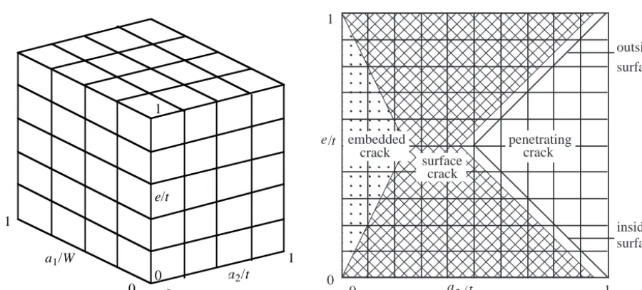
Figure 3 illustrates the probabilistic variables space. Because the probabilistic variables considered here are crack sizes in thickness and width directions, a1 and a2, and the location, e, the space becomes a 3-dimensional cube. For the conversion, the space can be divided to three areas, where (i) crack remains as embedded crack, (ii) crack is converted to surface crack, and (iii) crack penetrates through the plate, as shown in Fig. 4. Because the size of converted surface crack is a = e + a2, the lower half area (for inside surface) of Fig. 4 can be transformed to Fig. 5.
a2/t a1/W
e/t
0
1 1
1
0 0
0 a2/ t 1
0
e/t
1
outside surface
inside surface penetrating
crack embedded
crack
crack surface
Fig. 3 Probabilistic variables space Fig. 4 Area to be converted to surface crack
0
e/t
0.5
0
a/t = (e + a )/t2
1 1.5
0.5
0.95
0.5 0.75
penetrating crack
surface crack embedded
crack
Fig. 5 Area to be converted to inside surface crack as a function of size after conversion
The probabilistic density of converted surface crack distribution can be obtained by integration of density as shown by Eq.(6) from e/t = 0 to the upper limit of the hatching area. Then we obtain Eq.(7).
(7)
The last case, Case 4, is usual PFM analysis with surface cracks in exponential distribution. We will set the average crack size as the same as the size of embedded crack (6.248 mm), and 1.5 time (9.372 mm) from Eq. (7).
R E S U L T S
All calculations were performed with 32×32×32 divisions for embedded crack and 32×32 divisions for surface crack. While one thousand cracks were generated in Monte Carlo simulation, one point integration was used in the integration method. Obtained crack distributions and failure probabilities are compared below.
Crack distributions
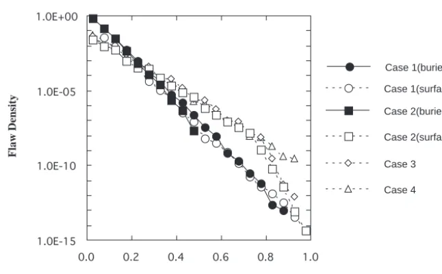
Figure 6 shows the crack size distributions for all cases. Because Monte Carlo simulation and integration method gave almost the same crack distributions, only those by the integration method are shown in the figure. The crack distributions for Case 2(surface) and Case 3 show very good agreement to each other. This result proves the deduction of Eq. (7).
1.0E-15 1.0E-10 1.0E-05 1.0E+00
0.0 0.2 0.4 0.6 0.8 1.0
Crack length, a/t
Case 4 Case 3 Case 1(surface) Case 1(buried)
Case 2(surface) Case 2(buried)
Flaw Density
Fig. 6 Crack distributions
Failure probabilities
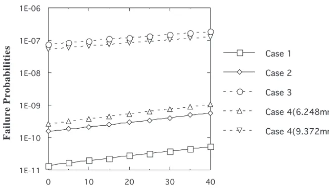
The results by Monte Carlo simulation were shown in Fig. 7. The results for Cases 3 and 4(ave. 9.372 mm) agree very well to each other, but give much larger failure probabilities than Cases 1 and 2. Crack distributions in Fig. 6 explain the agreement of Case 3 and 4. But the crack distributions for Cases 2 and 3 are almost identical from Fig. 6. One reason of the difference could be explained by the difference of aspect ratio. The elliptical embedded crack with aspect ratio, a2/a1, will be replaced by a semi-elliptical surface crack with aspect ratio, a/c = (2a2 + d)/a1 as shown in Fig. 8. From the figure, the aspect ratio of the surface crack should be larger than that of the embedded crack. In the calculations by integration method, this effect was considered for Case 3. Figure 9 shows the failure probabilities by the integration method. For Case 4, only
the larger value of average size was calculated. The results of Cases 1, 2, and 4 are almost the same to the results of Monte Carlo simulation in Fig. 7. This shows the precision of the integration method is permissible compared to Monte Carlo simulation. For Case 3, the failure probability reduces by one order from Fig. 7 to Fig. 9. The effect of aspect ratio seems significant for this case, but there is still a large discrepancy between Case 2 and 3. Although the surface crack model used in Case 3 is not quite precise, it gives conservative results and requires smaller computational resources.
1E-11 1E-10 1E-09 1E-08 1E-07 1E-06
0 10 20 30 40
Operating Years
Case 4(9.372mm) Case 4(6.248mm) Case 3
Case 2 Case 1
Failure Probabilities
Fig. 7 Failure probabilities by Monte Carlo simulation
2c
2a2 2a1
d a
1.0E-11 1.0E-10 1.0E-09 1.0E-08 1.0E-07
0 10 20 30 40
Year
Case 4 Case 3 Case 2 Case 1
F
ailur
e Pr
obabilities
Fig. 8 Conversion from embedded crack Fig. 9 Failure probabilities by integration method to surface crack
CONCLUSIONS
committee, i.e. “aged RPV under normal and upset operating conditions.” The result demonstrated that the integration method is permissibly precise compared to Monte Carlo simulation, the surface crack model used in Case 3 gives conservative results with much smaller computational resources. The embedded crack distribution gives the lowest value of failure probability. Then it should be used if there is available information about embedded crack distribution and the computational cost is permissible.
ACKNOWLEDGEMENT
This study has been performed as the part of the research in PFM subcommittee in Japan Welding Engineering Society, which is under the sponsorship from Japan Atomic Energy Research Institute.
REFERENCES
1. Yagawa, G., “Structural integrity assessment of nuclear power plants using probabilistic fracture mechanics,” Nuclear
Eng., Vol.34, 1988, pp.19-30. (in Japanese)
2. Harris, D. O. and Balkey, K. R., “Probabilistic considerations in life extension and aging,” Technology for the '90s, ASME PVP Division, 1993, pp.243-269.
3. Balkey, K. R., Closky, N. B. and Vermaut, M. K., “Application of risk-based methods to inservice inspection and testing,” Trans. 14th SMiRT, M05/2, Lyon, France, 1997.
4. JWES Report of PFM Subcommittee, JWES, JWES-AE-9705, 1997. (in Japanese)
5. Kanto, Y. and Yagawa, G., “Probabilistic fracture mechanics analysis of nuclear reactor pressure vessels: Effects of transition from embedded crack to surface crack,” Trans. 15th SMiRT, X-331-X-338, Seoul, Korea, 1999.
6. Final Report of RC111 Committee, Japan Society of Mechanical Engineers (JSME), 1995. (in Japanese)
7. Raju, I. S. and Newman, J. C., Jr., “Stress Intensity factors for internal and external surface cracks in cylindrical vessels,” Trans. ASME, J. Pressure Vessel Technology, Vol.104, 1982, pp.293-298.
8. Gamma, E., Helm, R., Johnson, R. and Vlissides, J., “Design Patterns Elements of Reusable Object-Oriented
Software,” Addison Wesley, 1995.
9. Lo, T. Y., Mensing, R. W. and Woo, H. H., “Probability of pipe failure of the reactor coolant loop of combustion engineering PWR plants: Vol.2 Pipe Failure Induced by Crack Growth,” NUREG/CR-3663 V02, UCRL-53500, 1985. 10. ASME, ASME Boiler & Pressure Vessel Code Section XI, Appendix A, 1973.
11. ASME, ASME Boiler & Pressure Vessel Code Section XI, Division 1, 1977.