High-count-rate
3He
position-sensitive
detector
system:
NEUNET-HCR
Setsuo Sato1,*, Tomohiro Seya1, Hidetoshi Oshita1, Hideto Kato2, Noriyuki Hikida2, Kazuya Ishizawa2, Akinori Yamaguchi3,
and Mitsugu Matsuura3
1High Energy Accelerator Research Organization, 1-1 Oho Tsukuba Ibaraki, Japan 2Canon Electron Tubes & Devices Co., Ltd., 1385 Shimoishigami Ohtawara Tochigi, Japan 3CLEAR PULSE Co., Ltd., 6-25-17 Chuo Ota-ku Tokyo, Japan
Abstract. Highly reliable 3He gas detectors are most often used in neutron scattering experiments but have
disadvantages such as low count rates and low position resolutions. In this study, a 3He gas detector system
called NEUNET-HCR was developed, whose count rate is approximately 10 times that of the current NEUNET system, which was developed for a high position resolution with a low count rate. NEUNET-HCR achieved a maximum count rate of 535 kcps per detector, with a loss of approximately 30%. As the NEUNET-HCR system was developed based on the NEUNET system, various improvements were required to achieve the high count rate. Further, a high count rate was achieved in the NEUNET-HCR system without significantly degrading the position resolution.
1 Introduction
Recently, the industrial use of neutrons has become widespread, and compact accelerator-driven neutron sources have been used to develop new materials. However, the development of neutron detectors that support these experimental facilities has been delayed, and 3He gas detectors are still used in many neutron
experiments. 3He gas detectors are the most reliable
neutron detectors and are typically utilized as position-sensitive detectors (PSDs) [1, 2]. However, these detectors have low count rates and low position resolutions. Therefore, joint research has begun between Canon Electron Tubes & Devices Co., Ltd. (CETD), which manufactures PSDs, and the High Energy Accelerator Research Organization (KEK), which develops readout circuits for neutron detectors. Consequently, improvements to compensate for these shortcomings have been made. Firstly, we developed a NEUNET system that increased the position resolution, and a position resolution of 2 mm or less in the axial direction was obtained with a PSD 1 m in length and 8 mm in diameter. However, we found that detectors with high count rates are demanded. Thus, we changed the focus of our research to achieve higher count rates. In this study, we succeeded in increasing the count rate to 535 kcps with approximately 30% loss. Even if the maximum count rate for practical usage is 200 kcps, the obtained count rate is approximately 20 times higher than that of the commercial 3He-PSD, which has a
maximum count rate of 10 kcps [2].
A high-count-rate readout circuit was developed based on a NEUNET system [1]. The NEUNET system
was originally designed based on the assumption that the PSD had a low count rate; therefore, the processing speed needed to be increased. However, when a high-count-rate readout circuit is used for a slow PSD, various characteristics are degraded and there is a risk of double counting. Therefore, the pulse width measurement method designed using another detector system [3] was applied to develop a method for distinguishing between fast and slow PSDs.
2 Readout circuit
The high-count-rate readout circuit was developed based on the NEUNET system. As the NEUNET system was designed for slow gas detectors with high position resolution, numerous improvements were necessary to achieve a count rate 10 times faster than that of the current system.
2.1 NEUNET system
The NEUNET system was developed with the objective of obtaining a position resolution (full width at half maximum, FWHM) of less than 2 mm with a length of 1 m. Figure 1 shows a typical PSD system with an effective length of 1 m, a detector diameter of 8 mm (top), and amplifiers, as well as a NEUNET circuit (bottom) embedded behind a shield. As the data output is obtained through only one network cable, small to large systems can be configured in a scalable manner.
of 1 m. Consequently, the amplifier was designed such that it can be installed behind the PSD.
Fig. 1. PSD system of 1 m length and 8 mm diameter.
Figure 2 shows the PSD amplifier board. Charge amplifier (AMP14b) boards are attached to and detached from an amplifier mounting (MAMP14b) board with connectors; these can easily be replaced individually. Nine AMP14b boards are attached to the MAMP14b board: eight boards are used for the actual measurements, and the other board serves as both an electric field shield and backup. The AMP14b is composed of a two-stage amplifier. The first-stage integrated circuit uses a low-noise, high-speed field-effect transistor operational amplifier. The soldered side of the board is almost completely grounded to minimize electric field crosstalk. In addition, input signal guards are installed to minimize charge leakage. The second stage is a pulse-shaping circuit that selects the pulse width that can pass through.
Fig. 2. PSD amplifier board.
Figure 3 shows the NEUNET board, which has 16-channel high-speed analog–digital converters (ADCs) that are processed by a field-programmable gate array (FPGA). The NEUNET board sends the data to a control PC by a network.
Fig. 3. NEUNET board.
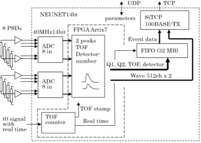
Figure 4 shows a block diagram of the NEUNET system. The 16 signals from both sides of the eight PSDs are amplified by AMP14b and converted into digital signals by ADCs on NEUNET. The waveform of the ADC output with the FPGA is analyzed to determine the pulse height as the charge corresponding to the neutron. If the signal is determined to be a neutron signal, the
time and detector number are added as event data and sent to the control PC by the network.
Fig. 4. Block diagram of the NEUNET system.
The ADC resolution was increased from 12 to 14 bits to achieve a high position resolution of 2 mm with a PSD length of 1 m. The position of the PSD was obtained from the ratio between the pulse heights of the charges from both ends, and each pulse height was obtained from the difference between the maximum peak and baseline of the ADC output. As the maximum range of the pulse height distribution was 14 bits, limiting it to 1/4 or more yields 12 bits as the position resolution of 4096 points. When 1 m is adjusted to 3000 points, 2 mm is 1/500 of 1 m; therefore, 2 mm is represented by 6 points and is a usable range.
The ADC used is a pipeline type that tends to diffuse the electrical noise at the input side. Although it has been reduced by ceramic capacitors, etc., it was not completely lost; therefore, a digital filter was programmed. A weighted moving average, which requires fewer circuits, was employed as the digital filter. No filter, 5, 13, and 16 clocks (no weighting factor) were tested. The 13-clock filter yielded the best results and was therefore adopted by default. Figure 5 shows the position distributions with the 13-clock filter and no filter. They were measured under the same conditions; however, the 13-clock filter has a much better position resolution than no filter. Although these techniques often conflict with the high count rate, they are in a trade-off relationship because they are important characteristics that are inherent in the PSD.
2.2 NEUNET-HCR system
Several improvements were required in the NEUNET system to ensure that the count rate of the NEUNET-HCR system would be 10 times faster.
• Adoption of a fast pulse-shaping time constant for the AMP14b: The pulse-shaping time constant of the AMP14b is approximately 10 times faster than that of the current board. However, when used with a slow PSD, the risk of double counting is increased and various characteristics are degraded.
• Adoption of a 1000BASE-T network IC: 100BASE-TX was used as the basic network IC; however, by changing to 1000BASE-T, it became possible to exceed the network speed of 12 MB/s.
• Change of the network transfer method: The network transfer method was changed from a handshake method to a one-way method. In the handshake method, the control PC informs NEUNET in advance of the maximum number of transfer bytes, and within that range, NEUNET sends back the data, including the number of transfer bytes, to the control PC. The network receive program specifies the number of received bytes before the transfer; however, the transfer direction is reversed for each handshake and the network flow is degraded. The one-way method simply sends data from NEUNET to the control PC for each neutron. It is suitable for high-speed transfer because it does not stop the network flow. From the measurement of the maximum transfer amount using a test pulse generator, this change improved from 0.5 M cps to 2.6 M cps per NEUNET.
• Deadtime control: When a slow PSD signal is amplified with AMP14b with a fast time constant, it sometimes counts the signal twice (double counting). Therefore, a certain dead time is provided after the pulse detection process in order to prevent double counting. For a fast PSD signal, there is no risk of double counting. Therefore, the dead time has been set to 0 for obtaining the high count rate. When a dead time of 800 ns is set, the count rate does not exceed 450 kcps per detector; however, when the dead time is set to 0 ns, the count rate exceeds 500 kcps. The dead time setting is, therefore, changeable.
• Histogram memory stoppage: The data storage method of a large-capacity memory also hinders speed. The large-capacity memory is indispensable for a smooth network transfer. As NEUNET is not a large-scale circuit, histogram data are stored in the same memory. Although these data are no longer used, they are inherited owing to their requirements in the previous system. Measurement without the histogram access using the test pulse generator improves from 2.1 M cps to 2.6 M cps per NEUNET.
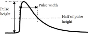
• Pulse width measurement function: A pulse width measurement function is provided to diagnose whether a PSD can increase the count rate. This technology [3] has been developed for other detector systems. Figure 6 shows the pulse width measurement method. The pulse width is obtained by acquiring the pulse height from the pulse waveform. To determine the pulse width, the
counting starts from the rising edge of the pulse and stops when it reaches half the height of the pulse.
Fig. 6. Pulse-width measurement method.
With these improvements and new functions, the limit of 4 MB/s for transferring 8 PSD data was increased to 21 MB/s. As there are 8 bytes of event data per neutron, an average transfer rate of 325 kcps per PSD is possible.
3
High-count-rate detector
A high-count-rate PSD can be achieved according to measurements of various conditions. Even with nearly the same gas composition and gas pressure, the characteristics often vary greatly with slight differences. If the tube diameter is short and the gas pressure is low, the PSD tends to have a high count rate.
3.1. Pulse width
AMP14b with a short pulse-shaping time constant was selected because the pulse width of the PSD output signal must be narrowed. In general, a signal slower than the pulse-shaping time constant becomes a pulse with a long width and low height, while a signal that is faster becomes a pulse with a short width and high height.
Figure 7 shows the pulse height versus width (PHW) graphs using the pulse width measurement function. The vertical axis is the pulse width (25 ns per channel), and the horizontal axis is the pulse height. Figure 7(a) shows that the entire signal gathers around 280 ns along the vertical axis, and it is a high-count-rate PSD (stopping gas: CF4, 3He gas pressure: 6 atm.). Figure 7(b) shows
that the low pulse height signal extends to around 700 ns, and it is a low-count-rate PSD (stopping gas: CF4, 3He
gas pressure: 20 atm.). The conditions are the same except that the gas pressure is different. As shown in these examples, the pulse width measurement function can identify a high-count-rate PSD. Because the fast PSD was filled with 3He gas of 8 mm diameter and a
pressure of 6 atm, the detection efficiency was estimated to be 19.8 % at the 1 Å neutron at an average of the tube. Similarly, because the slow PSD had a pressure of 20 atm, the efficiency was estimated to be 49.9 %. In this case, because the fast PSD detection efficiency is low, it is suitable for slow neutrons.
Figure 8 shows the trajectories of a triton and proton after the reaction between a neutron and 3He. The
neutron and 3He react, and the proton and triton fly in
opposite directions, ionizing the surrounding gas and consuming 746 keV of energy. When flying parallel to a core wire of the PSD, the charge arrives at the core wire almost simultaneously, resulting in a narrower pulse signal with a greater amplitude. When flying perpendicular to the core wire, the charge arrives at the core wire with time dispersion, resulting in wider pulse signal with a lower amplitude. If the generated charge is uneven with a slow PSD, there is a risk of double counting. If the charge transfer speed is faster than the pulse shaping time constant of the AMP14b, these are integrated into one pulse, resulting in a narrow and large-amplitude pulse signal.
Fig. 8. Trajectories of a triton and proton after the reaction between a neutron and 3He.
3.2 Time constants of AMP14b
The charge amplifier currently of the NEUNET system used at the Materials and Life Science Experimental Facility at the Japan Proton Accelerator Research Complex has an integration time constant of 25 µs and a pulse shaping time constant of 0.5 µs. As the pulse width spreads to approximately 3 µs and neutrons are received at an average of 30 µs with 10 % loss, the maximum average count rate is approximately 30 kcps. Because the setting is slow, good characteristics can be obtained from most PSDs.
For the high-count-rate PSD of NEUNET-HCR, the integration time constant was changed to 1 µs, and the pulse shaping time constant was changed to 0.05 µs, achieving approximately 10 times the original count rate. Figure 9 shows waveforms obtained when the pulse shaping time constant was 0.5 µs and 0.05 µs. In this case, the pulse widths are more than 5 times different.
Fig. 9. Pulse shaping time constants of (a) 0.5 µs and (b) 0.05 µs.
4 Experiment with a Neutron Source
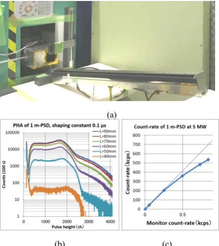
The high-count-rate experiment of the NEUNET-HCR system was performed at the B3 beam port at Kyoto University Research Reactor (KUR). The experimented PSD was filled with 14 atm. 3He gas in 8 mm diameter.
The detection efficiency was estimated to be 39.2 % at the 1 Å neutron at an average of the tube. As shown in Fig. 10(a), because the number of neutrons was insufficient, the effective thickness of the 3He gas was
increased by oblique beam injection, and it was measured with varying neutron beam intensity and calibrated with a monitor detector. Figure 10(b) shows the pulse height distribution map. As the beam intensity increases, the beam spreads up to approximately twice the height of the pulse peak because of a pileup. As depicted in the count-rate graph in Fig. 10(c), the maximum count rate of 535 kcps was obtained with a loss of less than 30 %.
(a)
(b) (c)
Fig. 10. (a) Oblique placement of the PSD on the beam. (b) Pulse height distribution. (c) Count rate.
Figure 11 shows the position distribution when neutrons were irradiated at seven points in 15 cm intervals. A pulse-shaping time constant of 0.1 µs yielded a better position resolution than 0.05 µs did. However, the FWHM was less than 6 mm at all points, and the performance as a PSD was maintained.
Fig. 11. Position distribution.
We developed a novel high-count-rate 3He PSD system.
A high count rate of 535 kcps was obtained with a loss of approximately 30%, which is very suitable for use in compact accelerator-driven neutron sources.
The authors wish to thank Dr. Tasaki and Mr. Hirose, who are in charge of the Kyoto University Accelerator-driven Neutron Source (KUANS). As they lent us the KUANS multiple times, we were able to collect a large amount of basic data for the high-count-rate study.
We also thank Dr. Mori, who is in charge of beamline B3 at KUR. We were able to prove that this system can withstand the high neutron count rate of the neutron reactor at KUR.
We also thank Dr. Otake and the staff at RIKEN, who recognized the superiority of this system and introduced it to RANS, a compact accelerator-driven neutron source at RIKEN.
This research was conducted in collaboration with CETD and KEK.
References
1. S. Satoh, S. Muto, N. Kaneko, T. Uchida, M. Tanaka, Y. Yasu, K. Nakayoshi, E. Inoue, H. Sendai, T. Nakatani, T. Otomo, NIMA, 600, 103–106 (2009), DOI 10.1016/ j.nima.2008.11.054
2. F. Liang, L. Chen, F. Li, G. Jin, Physics Procedia 37,
1813–1818 (2012), DOI
10.1016/j.phpro.2012.02.508