VIBRATION CONTROL OF CAR SUSPENSION
SYSTEM USING DIFFERENT CONTROLLERS
Gaurav Kumar Sinha
1, Prof. (Dr.) Upendra Prasad
2 1Research
Scholar, Electrical Department, Bit Sindri Dhanbad, (India)
2Associate Professor, Electrical Department, Bit Sindri Dhanbad, (India)
ABSTRACT
Optimal vehicle handling, good driving pleasure, best comfort for passengers, effective and efficient isolation of
road noise and vibration in suspension systems has been a key research area .This paper presents the
application of different controllers to control the vibration occurred in the car suspension system. When the
suspension system is designed, a ¼ model of car is used to simplify the problem to a one dimensional mass
spring- damper system. Its open-loop performance on the basis of time response is observed which depicts that
the car suspension has oscillations with large settling time. To overcome this problem, closed-loop system is
used. Despite continuous advancement in control theory, Proportional –Integral (PI),
Proportional-Integral-Derivative (PID) and H Infinity Control method are the popular technique to control any process. In this paper,
Proportional-Integral (PI) , Proportional-Integral-Derivative (PID) and H infinity controllers are used to
control the vibrations to give smooth response of the Car suspension system and carry-out their comparison on
the basis of time and frequency using Matlab environment.
Keywords:
Car Suspension System, Dynamic Modeling, H Infinity Control Proportional-Integral
Controller, Proportional- Integral-Derivative Controller.
I. INTRODUCTION
Increasing progress in automobile industry demands for Better riding capabilities and passenger comfort, to
produce highly developed model. The aim of the advanced car suspension system is to provide smooth ride and
maintain the control of the vehicle over cracks, uneven pavement of the road. Moreover, suspension system
modeling has an important role for realistic control design of the suspension.
In passive suspension system, spring and diminishing element is placed between the wheel and the car body.
They allow the forward compensation between the suspension stroke deviation and the driving comfort.
According to the car structural feature, suspension stroke is limited for some specified values. Riding comfort
reduces as suspension deviation reached these limited specified values.
In active suspension system, a hydraulic system which is controlled by feedback controller is placed between the
wheel and the car body. Controlled suspension system allows forward compensation between the performance
criteria of suspension deviation and the riding comfort . Nowadays, different types of controllers are used to
Fuzzy controller . In this paper, PI, PID and H Infinity controllers are designed to control the vibration occurred
in car suspension system using SIMULINK/MATLAB .
II. THE CAR SUSPENSION SYSTEM
Car Suspension is the system of springs, shock absorbers and linkages that connects a car to its wheels
and allows relative motion between the two. Suspension system serves a dual purpose- contributing to the
vehicle's road holding/handling and braking for safety purpose and pleasure driving, and keeping vehicle
occupants comfortable and isolated from road noise, bumps, and vibrations, etc.
2.1 Modeling and System Analysis
Fig.1: Passive Quarter Car suspension system
2.2 Parameters of Car Suspension System
•(M1) 1/4 car body mass - 1900kg•(M2) suspension mass - 280 kg
•(K1) spring constant of suspension system-50,000 N/m •(K2) spring constant of wheel and tire - 350,000 N/m •(B1) damping constant of suspension system -250 N.s/m •(B2) damping constant of wheel and tire 13,050 N.s/m •(U) Control force
2.4 Simulink Implementation of a car suspension system
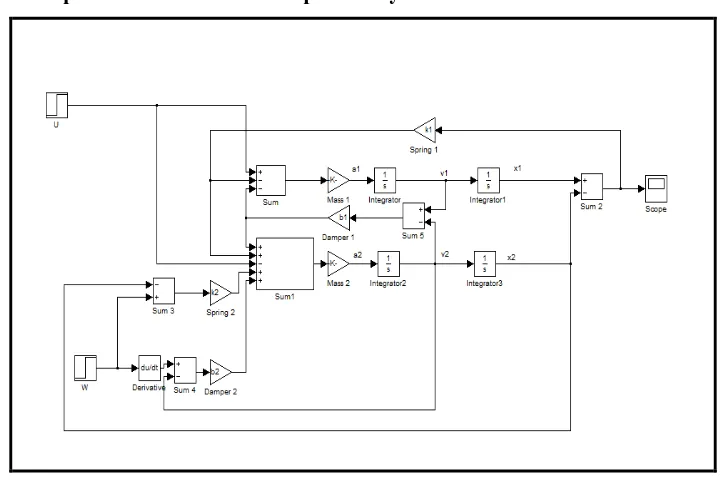
Fig. 3: Simulink Model of Car Suspension System
The car suspension shown in Figure 1 has been implemented in SIMULINK as shown in Figure 3 .
The MATLAB/SIMULINK is used to display how the original open-loop system performs without any
feedback control. The response of the system to a unit step actuated force input and unit step disturbance input is
observed. The road disturbance in this problem will be simulated by a step input. This step could represent the
car coming out of a pothole.
Fig. 4: Amplitude Vs Time Response Fig. 5: Amplitude Vs Time With Bump
system is under-damped. People sitting in the Car will feel very small amount of oscillation. Moreover, the Car takes
an unacceptably long time to reach the steady state (the settling time is very large).
0 5 10 15 20 25 30
0 0.5 1 1.5 2 2.5 3 3.5
4x 10 -5 Step Response Time (sec) A m p li tu d e
open loop step response of car suspension system
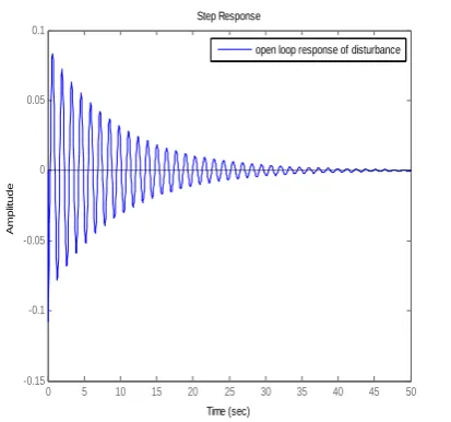
0 5 10 15 20 25 30 35 40 45 50
-0.15 -0.1 -0.05 0 0.05 0.1 Step Response Time (sec) A m p lit u d e
open loop response of disturbance
Fig. 6: Open-loop step response of Car Fig.7: Open –loop step response of disturbance
Suspension System
Now we can see the response for a step disturbance input, W(s), with magnitude 0.1 m. When consider the
disturbance input W(s) only, set U(s) = 0. Thus, observe an Open-Loop response of unit step disturbance force as shown in Fig .7.
It is observed from the open-loop response that for a unit step actuated force; the system is under-damped. The
overshoot is about 0.08 and settling time is 35 sec. People sitting in the Car will feel very small amount of
oscillation but it takes an unacceptably long time to reach the steady state (the settling time is very large). The
solution to this problem is to add a controller into the system to improve the performance.
III. CONTROLLER
A controller is a device, may be in the form of analogue circuit, chip or computer that monitors and physically
alters the operating conditions of a given dynamical system. From the past decades, the importance of the
control system has been increased due to the increment in complexity of the system under control and to
achieve optimum performance of the system. The block diagram of closed-loop Car Suspension System is
shown in Fig.8.
In this paper, three controllers, Proportional-Integral (PI) Controller, Proportional-Integral-Derivative (PID)
Controller and H infinity controller are used to improve the response of the system.
3.1. Proportional-Integral Controller
The combination of proportional and integral terms is important to increase the speed of the response and also to
eliminate the steady state error. C(s) the transfer function of PI controller has the form of
C(s) =KP + KI ∕S
(1)
Fig. 9: Block Diagram of PI controller
Where, KP is proportional gain and KI is an Integral gain. The proportional term (sometimes called gain) makes a
change to the output that is proportional to the current error value. The proportional response can be adjusted by
multiplying the error by a constant Kp, called the proportional gain. The contribution from the integral term
sometimes called reset is proportional to both the magnitude of the error and the duration of the error.
3.2 Proportional-Integral-Derivative Controller
A proportional-integral-derivative controller (PIDcontroller) is a generic control loop feedback mechanism
widely used in industrial control systems - a PID is the most commonly used feedback controller.
A PID controller calculates an "error" value as the difference between a measured process variable and a desired
set point. The controller attempts to minimize the error by adjusting the process control inputs. In this section, the
method to obtain the controller for the car suspension system is described when a PID scheme is used to perform
control actions and C(s) the transfer function of PID controller has a form
C(s) = KP + KI ∕S +KD S (2)
Fig. 10: Block Diagram of PID controller Fig.11: H controller connection for suspension
The PID controller calculation involves three separate parameters, and is accordingly sometimes calledThe proportional value determines the reaction to the current error, the integral value determines the reaction
based on the sum of recent errors, and the derivative error has been changing. The weighted sum of these three
actions is used to adjust the process via a control element such as the disturbances of a Car suspension system.
3.3 H Infinity controller
In this type of optimal control method, controllers in this section are designed using linear H Synthesis . As is
standard in the H framework, the performance objectives are achieved via minimizing weighted transfer
function norms. Weighting functions serve two purposes in the H framework: They allow the direct comparison
of different performance objectives with the same norm, and they allow for frequency information to be
incorporated into the analysis. A block diagram of the H control design interconnection for the active
suspension problem is shown in Fig.11.
x1:=x , , x3:= xus and
Following is the state-space description of the quarter car dynamics:
A linear ,time invariant model of the quarter car model , qcar, is constructed from the equations of the motions
and the parameter values. The inputs to the model are the road disturbances and the actuator force, respectively,
and the outputs are the car body deflection , acceleration and suspension deflection.
IV.DESIGN OF PI, PID & H INFINITY CONTROLLER
In this section, PI PID and H Infinity Controllers are applied to the Car Suspension System. To design these
Controllers MATLAB/SIMULINK is used.
4.1 Design of PI Controller
The test presented in this section is related to the PI Controller performance for the car suspension system. The main
purpose of this implementation is to get the desired response of the system. The Simulink model of the Car
Suspension system using PI Controller is shown in Fig. 12
The values of KP and KI are 832100 and 624075 respectively are taken. The response of the Car Suspension
System using PI Controller is shown in Fig. 14. Figure 11 depicts that the people sitting in bus feels small
amount of oscillations for 5 seconds. Without derivative action, a PI-controlled system is less responsive to real
and relatively fast alterations in state and so the system will be slower to reach set-point and slower to respond
to perturbations than a well-tuned PID system.
Fig.14: Response of Car Suspension System using PI Controller
4.2 Design Of PID Controller
The test presented in this section is related to the PID Controller performance for the bus suspension system. The main
purpose of this implementation is to get the desired response of the system. The Simulink model of the Car Suspension
system using PID Controller is shown in Fig. 15.
Fig. 15 & Fig. 16. Simulink Model of Car Suspension System using PID Controller
The values of KP, KI and KD are 832100, 624075 and 208025 respectively. The response of the Car SuspensionSystem using PID controller is shown in Fig. 16. The Fig. 16 depicts that the people sitting in the Car feels very
small amount of oscillations in 2 seconds. By the use of PID Controller, the performance characteristics of Car
suspension System are drastically improved.
Fig. 18
.Comparison response of Open-loop Car Suspension System using PI and PID
Controller
It is observed from the comparison of the Open-loop Car Suspension System using PI and PID controller is that
the PID controller has less overshoot and has very small settling time i.e. 2 seconds as compare to others .The
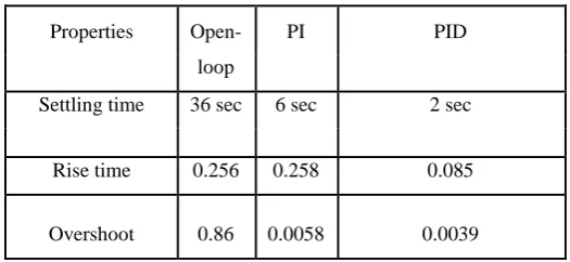
analysis of Fig.18 is tabulated in Table 1 ,
Table 1 Comparison of Different controllers with Open-Loop
4
.3 H Infinity Controller Design
As shown in Fig. 11 the measured output or feedback signal y is the suspension deflection x1-x3. The
controller acts on this signal to produce the control input, the hydraulic actuator force fs. The block Wn serves
to model sensor noise in the measurement channel Wn is set to a sensor noise value of 0.01 m. displacement
sensor. The weight Wref is used to scale the magnitude of the road disturbances. Assume that the maximum
road disturbance is 7 cm and hence choose Wref = 0.07.
The magnitude and frequency content of the control force fs are limited by the weighting function Wact.
Wact = 100s+50/13s+500. The magnitude of the weight increases above 50 rad/s in order to limit the closed-loop bandwidth. The purpose of the weighting functions wx1 and Wx1-x3 is to keep the car deflection and the suspension deflection small over the desired frequency ranges. In the first design, you are designing the
controller for passenger comfort, and hence the car body deflection x1 is penalized. The weight magnitude rolls off above 5x2 pi rad/s to respect a well-known H design rule of thumb that requires the performance
weights to roll off before an open-loop zero (56.7 rad/s in this case).
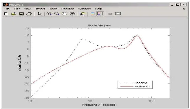
An H infinity controller is synthesized with the hinfsyn command. There is one control input, the hydraulic
actuator force, and one measurement signal, the car body acceleration and can be analised the H controller by
constructing the closed-loop feedback system CL1. Bode magnitude plots of the passive Robust H infinity
optimal methods have been applied in the active suspension design of in-wheel motor driven vehicle. Simulation
results indicates that the robust H infinity optimal controller not only improve the vehicle stability and handing
Properties Open- PI PID
loop
Settling time 36 sec 6 sec 2 sec
Rise time 0.256 0.258 0.085
and when dealing with the parameter uncertainties of the vehicle, manifests the good robustness. We observed
that active suspension can not only improve the effects of increased unsprung mass of the vehicles, but also the
robust H infinity optimal controller can present better performance of the stability of the system.
Figure 19.. Bode magnitude plot for active and passive car suspension
V. CONCLUSION
In this paper, PI ,PID, and H infinity Controllers have been designed and employed for controlling a suspension
system of a ¼ Car model. The control scheme has been implemented in SIMULINK and compared the response
of open-loop, PI ,PID and H Infinity controllers. The overshoot of open loop response is observed as 0.08 and
settling time is 35sec which signifies that people sitting in the car feels small amount of oscillation for
unacceptably long time. When PI controller is used with this system, it is observed that the overshoot decreases
to 0.0058 and settling time becomes too short about 6 sec which satisfies designed criteria up to some extend.
For further improvement, PID controller is used and it has been observed that the overshoot decreases to 0.0039
and response is settled at 2 sec which is a desired response of the suspension system. The proposed model is
aimed to developed and carry the response of system using PID controller up to a better level.
A separate analysis of H infinity control method is also been carried out in this paper which also improves the
ride quality , vehicle stability and handling . We observed that active suspension can not only improve the
effects of increased unsprung mass of the vehicles, but also the robust H infinity optimal controller can present
better performance of the stability of the system.
REFERENCES
[1] Kuo Y. P. and T. H. S. Li, “GA-Based Fuzzy PI/PID Controller for Automotive Active Suspension
System”, IEEE Transactions on Industrial Electronics, vol. 46, pp. 1051–1056, December 1999.
[2] Zhuang, M. and D. P. Atherton, “Automatic tuning of optimum PID controllers,” IEEE Proceeding Part
[3] Sheilza Aggarwal and Manisha Garg, “Design and Simulation of PID controller of nanopositioner for
minimum integral of error”, International Journal of Engineering Sciences (ISSN) online-2277-9698,
127-132, 2012.
[4] K. Matsumoto, K. Yamashita and M. Suzuki, “Robust H∞ -output feedback control of decoupled
automobile active suspension system”, IEEE Transaction on Automatic Controller, vol. 44, pp.392-396,
1999.
[5] Elmadany, M., “Integral and state variable feedback controllers for improved Performance in automotive
vehicles”, Computer Structure., vol. 42, no. 2, pp. 237-244, 1992.
[6] Isobe, T. and O. Watanabe, “New semi-active suspension controller design using quasi-linearlization and