1587 |
P a g e
Numerical investigation of unsteady incompressible
viscous flow over flat plate having rectangular obstruction
using vorticity-stream function approach
Rupam Deka
1, K. K. Das
2 1Mechanical Engineering Department,
Dibrugarh University Institute of Engineering and Technology, Dibrugarh, (India)
2
Mechanical Engineering Department, Assam Engineering College, Guwahati, (India)
ABSTRACT
In this work an attempt has been made to numerically simulate the effect of the flow past a flat plate having
rectangular bluff body. A CFD code has been developed based on two-dimensional unsteady Navier-Stokes
equations using Vorticity-Stream function approach. Results are in good agreement with the benchmark
computation of flow over rectangular bluff body. The influences of the height of the bluff body and location of
the bluff body have been investigated.
Keywords: Bluff Body, CFD, Stream Function, Simulation, Vorticity.
I INTRODUCTION
The study of wind flow over buildings has been an active area of research for several decades. Numerous
experimental studies have been carried out to understand the flow behaviour of the wind when it interacts with a
structure. The interaction of the wind with the building and building like structures affect the pedestrian
comfort, pollution dispersion and also the ventilation within the building. In the present study, the physical
problem of wind flow over a building has been simulated numerically.
In the present work a numerical code has been developed to study the flow around an obstruction. The
two-dimensional Navier-Stokes equations have been solved using vorticity-stream function formulation.The
numerical code developed has been used to predict the flow field and vorticity distribution. The effect of heights
of the obstruction on the flow field is studied. Further, the variation of approach length to the obstruction on the
flow is also studied.
The type of flow produced by the bluff bodies or building like structures in their wakes, particularly as regards
the amount and level of organization of the vorticity field has the greatest importance both from the aero
dynamical and from the design points of view. The numerical modelling of such type of flow is extremely
difficult. However, experimental investigation is quite laborious, time consuming and costly.
Harlow & Welch (1965) [1] described a new technique for the numerical investigation of the time-dependent
flow of an incompressible flow. The boundary of the flow is partially confined and partially free. The new
1588 |
P a g e
aerodynamic behavior of square cylinder in a uniform flow at high Reynolds numbers. They obtained the
numerical solution for the unsteady flows by direct integration of the 2-D and 3-D incompressible Navier-Stokes
equations in the generalized coordinate system. A systematic study has been carried out for the 3-D evaluation
of wind flow around a building with emphasis on the boundary treatment by Stathopoulos &Bhaskaran (1990)
[3]. Differential equations are discretized into difference form using the control volume method. Qasim et
al.(1992) [4] performed 2-D computations to simulate the flow over the Field Test Facility Building located at
Texas Tech University. Texas Tech Building is approximately 9.1m wide, 13.7m long and 4.0m high.Pearce et
al. (1992) [5] investigated the periodic shedding of vortices from bluff body geometries with a 2D finite
difference code.Zhang et al. (1993) [6] have investigated the effects of incident shear and turbulence on flow
around building by a turbulent kinetic energy/dissipation k-ε model. Castro et al.(1997) [7] presented some
aspects of computational work undertaken as part of a multipartner European Union projects on flow and
dispersion around building.Bouris&Bergeles (1999) [8] have performed a two-dimensional large eddy
simulation of the quasi-two-dimensional turbulent flow past a square cylinder with no-slip boundary conditions
at the solid walls. Gao &Chow (2005) [9] studied air approach flow moving towards a cube. The RANSequation
types of k-ε turbulence model are used. Flow separation at the corner above the top of the cube, level of
separation and reattachment were investigated.
II GOVERNING FLOW EQUATIONS
In this work 2D unsteady Navier-Stokes equation has been solved using vorticity-stream function approach. The
governing equations are vorticity transport equation and Poisson’s equation.
2 2 2 21
y
x
R
y
v
x
u
t
e
(2.1)x
v
y
u
y
u
x
v
2 2 2 2y
x
(2.2)Where
is the vorticity,
is the stream function, u and v are x and y component of velocity.III METHODOLOGY
The governing equations are converted into algebraic equations before being solved. The Finite Difference
Method (FDM) has been used for the same and in this Forward Time Central Space (FTCS) scheme has been
adopted.
The vorticity equation is parabolic, which is solved by time marching procedures whereas the stream function is
elliptic and is solved by successive over relaxation methods (SOR). Thus, at every time step, both parabolic and
1589 |
P a g e
The number of grid points amounted to 150(x- direction) X 100(y- direction) = 15,000. The grid size is uniform
throughout the zone. The computational domain has a downstream length and vertical height of 20 times the
width of the obstruction and upstream length of 10 times of the width of the obstruction. The Reynolds number
of the flow is 7000.
3.1 Boundary Conditions:
Impermeable no slip boundary condition has been applied on the solid boundary. The time marching procedure
for solving the vorticity transport equation requires appropriate expressions for Ψ and ξ at the boundaries. The
specifications of these boundary conditions are extremely important since it directly affects the stability and
accuracy of the solution. Vorticity value at the inflow is taken as zero. Near the wall vorticity is given by
2
1 w w
+0.∆n,where∆n is the distance from (w + 1) to w, normal to the wall. At the outflowx
is taken as
0. Stream function is assumed to be equal to U.y and at the outflow x
= 0.On the solid surface it is having
zero value. At inflow u = U and v = 0. At the outflow ∂u/∂x = ∂v/∂x = 0. At the far field u = U and v = 0. The
velocities u = v = 0 at the walls due to no slip boundary condition.
IV RESULTS AND DISCUSSION
The flow characteristics over a rectangular building are shown in terms of streamline contour, vorticity contour
and velocity profiles at various locations. The results are shown for Re = 7000.
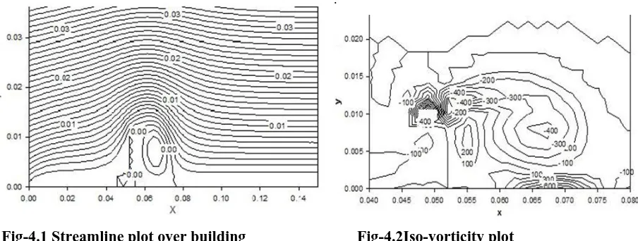
Figure 4.1 shows the streamline plot and figure 4.2 shows the iso-vorticity plot. It is observed that the
streamlines move downstream of the obstruction in curved paths. Behind the obstruction the streamlines have
clockwise circular movements forming a rectangular zone characterized by flow reversal.
.
Fig-4.1 Streamline plot over building
Fig-4.2Iso-vorticity plot
Both streamline pattern and iso-vorticity plots show that the flow field is fully turbulent and is characterized by
1590 |
P a g e
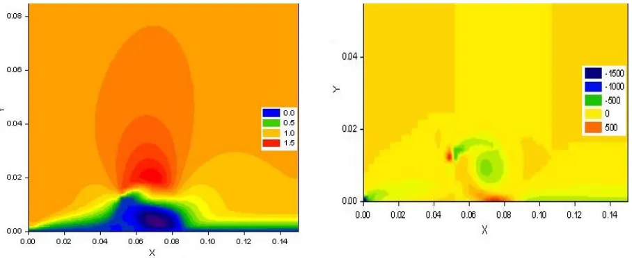
Fig-4.3 u Velocity contour for a normalised Figure-4.4 vorticity contour for abuilding height
(h=0.01)normalised building height (h=0.01)
Figure 4.3 and figure 4.4 show the u contour and vorticity contour for the normalised height (h=0.01) of the
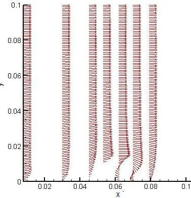
obstruction. Figure4.5 shows the velocity vector plot over a flat plate in the presence of a rectangular obstruction
at different locations. The obstruction has been placed at a normalised distance 0.05 from the inflow. In the
upstream of the obstruction the velocity profile is similar to that observed over a flat plate. As we move closer to
the obstruction the velocity profile is modified. Reversal of flow is observed downstream of the obstruction. As
we move further away this effect diminishes
.
Fig- 4.5 Velocity profiles at different locations Fig-4.6 Velocity vector plot
In the figure-4.6 it has observed that stagnation occurs near the wall at inflow and windward side of the
1591 |
P a g e
Fig-4.7 u Velocity contour for a normalised Fig-4.8 vorticity contour for normalised building
building height(h=0.008) height (h=0.008)
Figure 4.7 and figure 4.8 show the u contour and vorticity contour for the normalised height (h=0.008) of the
obstruction.Figure 4.9 and figure 4.10 show the u contour and vorticity contour for the normalised height
(h=0.012) of the obstruction. It is observed that with increase in height of the obstruction, the zone of
disturbance in the downstream increases. The recirculation in the downstream is higher for greater height. The
region above the building has higher disturbance for taller buildings.
Fig- 4.9 u velocity contour for a normalised Fig-4.10 vorticity contour for normalised building
building height (h=0.012) height (h=0.012)
V.CONCLUSION
A numerical code based on 2D N-S equations has been developed using vorticity-stream function formulation.
The code has been used to study the flow over a flat plate having a rectangular obstruction of different heights
and at different distances from the leading edge. The results have been obtained in terms of streamline and
iso-vorticity lines, velocity profile and velocity vectors at different locations. The results show that the height of the
1592 |
P a g e
of disturbance in the downstream increases.The recirculation in the downstream is higher for greater height. In
case of a taller obstruction a higher pressure drop occurs in the wake of the obstruction. Due to the variation in
approach length the boundary layer formation in upstream of the obstruction has a prominent effect on the flow
field around the obstruction.
REFERENCES
[1] Harlow F H & Welch J E (1965), “ Numerical Calculation of Time-Dependent Viscous Incompressible Flow of Fluid with Free
Surface”, Phys. of Fluid, Vol.8, No.12, pp.2182-2189.
[2] Tamura T &Kuwahara K (1990), “ Numerical Study Of Aerodynamic Behavior of Square Cylinder” , Jl. Of Wind Engineering &
Industrial Aerodynamics, Vol. 33, pp. 161-170.
[3] Stathopoulos T &Bhaskaran A (1990) ,“ Boundary Treatment for the Computation of Three-Dimensional Wind Flow Conditions
Around a Building”, Jl. Of Wind Engineering & Industrial Aerodynamics, Vol. 35, pp. 177-200.
[4] Qasim A, Maxwell T T&Parameswaram S (1992) “Computational Prediction of Flow Over a 2-D Building” Jl.Of Wind Engineering &
Industrial Aerodynamics, Vol.41-44, pp. 2839-2840.
[5] Pearce J. A, Qasim A, Maxwell T. T &Paramesawaran (1992) “A Computational Study of Coherent Wake Structure Behind 2-D
Bluff Bodies”, Jl. Of Wind Engg. & Industrial Aerodynamics, Vol.41-44, pp.2853-2861.
[6] Zhang Y Q , Huber A H , Arya S P S & Snyder W H (1993), “ Numerical Solution to determine the effects of incident Wind Shear
and Turbulence Level On the Flow Around a Building”, Jl. Of Wind Engineering & Industrial Aerodynamics, Vol. 46 & 47, pp.
129-134.
[7] Cowan I R , Castro I P & Robins A G (1997), “ Numerical consideration for simulation of flow & dispersion around buildings” , Jl.
Of Wind Engineering & Industrial Aerodynamics, Vol. 67 & 68, pp. 535-545.
[8] BourisD &Bergeles G (1999 ) , “ 2D LES of vortex shedding from a square cylinder” , Jl. Of Wind Engineering & Industrial
Aerodynamics, Vol. 80, pp. 31-46.
[9] Gao Y & Chow W. K (2005), “Numerical studies on air flow around a cube”, Jl. Of Wind Engg. & Ind. Aerodynamics, Vol. 93, pp.