Scholarship at UWindsor
Scholarship at UWindsor
Electronic Theses and Dissertations
Theses, Dissertations, and Major Papers
1-1-2004
Active suspension simulation through software interfacing.
Active suspension simulation through software interfacing.
Joseph Maiorana
University of Windsor
Follow this and additional works at:
https://scholar.uwindsor.ca/etd
Recommended Citation
Recommended Citation
Maiorana, Joseph, "Active suspension simulation through software interfacing." (2004). Electronic Theses
and Dissertations. 6954.
https://scholar.uwindsor.ca/etd/6954
A
c t i v eS
u s p e n s i o nS
i m u l a t i o nT
h r o u g hS
o f t w a r eI
n t e r f a c i n gB Y
J
o s e p hM
a i o r a n aA THESIS
SUBM ITTED TO THE FACULTY OF GRADUATE STUDIES AND RESEARCH THROUGH THE DEPARTM ENT OF MECHANICAL, AUTOM OTIVE, AND MATERIALS ENGINEERING IN PARTIAL FULFILM ENT OF THE REQUIREM ENTS FOR THE DEGREE OF M ASTER OF APPLIED
SCIENCE AT THE UNIVERSITY OF W INDSOR
Wi n d s o r, On t a r i o, Ca n a d a
2004
1*1
Published Heritage Branch
Direction du
Patrimoine de I'edition
395 W ellington Street Ottawa ON K1A 0N4 Canada
395, rue W ellington Ottawa ON K1A 0N4 Canada
Your file Votre reference ISBN: 978-0-494-34957-1 Our file Notre reference ISBN: 978-0-494-34957-1
NOTICE:
The author has granted a non
exclusive license allowing Library
and Archives Canada to reproduce,
publish, archive, preserve, conserve,
communicate to the public by
telecommunication or on the Internet,
loan, distribute and sell theses
worldwide, for commercial or non
commercial purposes, in microform,
paper, electronic and/or any other
formats.
AVIS:
L'auteur a accorde une licence non exclusive
permettant a la Bibliotheque et Archives
Canada de reproduire, publier, archiver,
sauvegarder, conserver, transmettre au public
par telecommunication ou par I'lnternet, preter,
distribuer et vendre des theses partout dans
le monde, a des fins commerciales ou autres,
sur support microforme, papier, electronique
et/ou autres formats.
The author retains copyright
ownership and moral rights in
this thesis. Neither the thesis
nor substantial extracts from it
may be printed or otherwise
reproduced without the author's
permission.
L'auteur conserve la propriete du droit d'auteur
et des droits moraux qui protege cette these.
Ni la these ni des extraits substantiels de
celle-ci ne doivent etre imprimes ou autrement
reproduits sans son autorisation.
In compliance with the Canadian
Privacy Act some supporting
forms may have been removed
from this thesis.
While these forms may be included
in the document page count,
their removal does not represent
any loss of content from the
Conformement a la loi canadienne
sur la protection de la vie privee,
quelques formulaires secondaires
ont ete enleves de cette these.
A
b s t r a c tActive suspensions provide favourable characteristics over traditional passive vehicle suspensions
since they are able to find a better compromise between ride and handling, a conflict that plagues all
conventional suspensions. However, active suspension has yet to break into production vehicles because o f
the technical issues that rem ain to be resolved to improve its implementation.
Effective virtual simulation o f such a system requires a method o f properly modeling a multi
domain system. Software interfacing is a method that may be used to solve such problems. It allows each
sub-system to be modeled in its natural dom ain software and then links the sub-systems together, allowing
the input and output values for each program to be exchanged with the rest o f the model. W ith this
technique, modelling simplifications o f each domain is avoided by allowing a complete and accurate picture
o f the system to surface before prototyping begins.
This research focuses on simulating active suspension by combining the m ultibody dynamic
software program o f ADAMS (Automatic Dynamic Analysis o f M echanical Systems) with
Matlab/Simulink. The purpose is to capture the dynamics o f the system which would allow the user to tune
and optimize the suspension before prototyping. Since it is geared towards passenger vehicles, this study
focuses on the ride behaviour o f the vehicle rather than its handling abilities.
A quarter car and full car model are implemented for both the traditional lumped mass model and
the Bombardier litis utility truck. W hen interfacing with the Simulink controller, nonlinear and linear
versions o f the ADAMS vehicle model were used; also a fully-active and semi-active suspension was
evaluated for comparison with the passive suspension. In addition, a Kalman filter for state estimation was
used with the fully-active controller, while bushings are added to the full car litis vehicle.
The nonlinear ADAMS vehicle was able to successfully communicate with Sim ulink to simulate
the above systems. Results also indicate that the linear vehicle models are reasonable in their performance
and so are useful for quick prelim inary studies. Additionally, the simple lumped mass vehicle demonstrated
similar response patterns and features as the m ore complicated litis models, further proving the worth o f
these models.
Results demonstrate that a fully-active suspension is able to significantly increase ride
performance over a passive suspension but at the cost o f the suspension displacement. As expected the
semi-active suspension perform ance was intermediate to that o f the passive and fully-active system but with
the advantage o f only dissipating energy and not consuming it. Both semi-active and fully-active controllers
performed reasonably well for this investigation, however, shortcomings in each were noticed. The Kalman
filter was generally able to estimate the system states which make the fully-active controller use all the
m ore viable for real world application.
"The only true wisdom is in knowing you know nothing."
-Socrates
"Real knowledge is to know the extent o f one's ignorance."
-Confucius
A
c k n o w l e d g e m e n t sFirst I would like to thank Dr. Bruce M inaker who started it all by graciously agreeing to become
my principal advisor. His encouraging guidance combined with his contagious enthusiasm for engineering
made him a delight to work with.
My deepest appreciation goes out to my industrial advisor Dr. Dajun Zhang o f DaimlerChrysler,
whose support, humility and technical expertise is inspirational. He patiently sat through long discussions
with me on the project while answering my questions carefully and thoughtfully.
In addition I would like to thank my co-advisor Dr. Peter Frise who supported this project and
endorses others like it to the highest level.
M any thanks to Mr. M ohammed M alik o f DaimlerChrysler who helped make it possible to
conduct this research at the University o f W indsor DaimlerChrysler Automotive Research and
Development Centre (ARDC).
Furthermore I would like to acknowledge those at ARDC whose support o f this project and others
like it, expose students to cutting edge research that bridges the gap between academ ia and industry. I
would also like to thank my co-workers at ARDC whose support was instrumental to the completion o f this
project.
Last but not least I would like to thank my parents Lina and M atthew and my sister Claudia
without whom I would never have succeeded this far.
A
b s t r a c t... in
D
e d i c a t i o n...
iv
A
c k n o w l e d g e m e n t s...
v
T
a b l e s...
xi
F
i g u r e s... x»
N
o t a t i o n... xvi
S
y m b o l s... xvii
1 I
n t r o d u c t i o n 1.0 Problem S y n th esis... 11.1 Ride versus H a n d lin g ... 2
1.1.1 M odel D escrip tio n ... 2
1.1.2 Spring C o n flic t... 2
1.1.3 Damper C o n flic t... 5
1.2 The Active S o lu tio n ... 6
1.2.1 Fully-Active S u sp en sio n ... 6
1.2.2 Semi-Active S uspension ... 6
1.2.3 System P ro b le m s... 7
1.3 Software In terfacin g ... 7
1.4 O b jectiv es... 8
2 L
it e r a t u r eR
e v i e w 2.0 Active Suspension A p p licatio n ... 92.0.1 Active Anti-Roll B a r ... 9
2.0.2 Variable Geometry S u sp en sio n ... 10
2.0.3 Rheological Semi-Active D a m p e r... 10
2.0.4 Active Body C o n tro l... 10
2.0.5 Lotus Active S u sp en sio n ... 11
2.0.6 Citroen Hydraulic S u sp en sio n ... 11
2.0.7 litis Active S uspension ... 11
2.1 Virtual Active R ese a rc h ... 12
2.1.1 Linear Quadratic Regulator (L Q R )... 12
2.1.2 Linear Quadratic Gaussian Regulator (L Q G )... 13
2.1.3 Semi-Active C o n tro l... 13
3 T
h e o r e t i c a lP
r i n c i p l e s3.0 Global Coordinate S y ste m ... 16
3.1 A D A M S ... 16
3.1.1 M ultibody D y n am ics... 16
3.1.1.1 Generalized C oordinates... 17
3.1.1.2 J o in ts ... 18
3.1.1.3 M o tio n ... 18
3.1.1.4 Dynamic Equations o f M o tio n ... 18
3.1.2 Solver T ech n iq u es... 20
3.1.2.1 ADAMS S o lv e r... 20
3.1.2.2 Alternative S tra te g y ... 21
3.1.2.3 Linearization A lg o rith m ... 22
3.2 Control A lg o rith m ... 23
3.2.1 Linear Quadratic R e g u lato r... 23
3.2.1.1 Cost F u n c tio n ... 24
3.2.1.2 Solution C o n d itio n ... 25
3.2.2 State O b se rv e r... 25
3.2.2.1 Kalman-Bucy F ilte r ... 26
3.2.3 State Estim ate Feedback C o n tro l... 27
3.2.4 Skyhook and Ground-Hook D a m p e r... 27
3.2.5 Semi-Active C o n tro l... 28
3.3 Software In te rfa c e ... 28
3.3.1 Function Evaluation Method/Continuous M o d e ... 29
3.3.2 Cosimulation M ethod/Discrete M o d e ... 29
3.3.3 Interface N o te s ... 30
4 V
ir t u a lM
o d e l 4.0 V e h ic le ... 314.0.1 Lum ped M ass V e h ic le ... 32
4.0.1.1 Quarter Car M o d e l... 32
4.0.1.2 H alf Car M o d e l... 32
4.0.1.3 Full Car M o d e l... 33
4.0.1.4 S and G M o d e l... 33
4.0.2 Bombardier litis Utility T ru c k ... 34
4.0.2.1 Force E le m e n ts... 35
4.0.2.2 Virtual M o d e l... 35
4.0.2.3 Quarter Car M o d e l... 36
4.0.2.4 Full Car M o d e l... 37
4.1 C o n tro ller... 38
4.1.1 Linear Quadratic R e g u la to r... 38
4.1.2 Kalman-Bucy F ilte r ... 38
4.1.3 Semi-Active C o n tro l... 39
5 INTERFACE PROCESS
5.0 ADAM S/M atlab In te rfa c e ... 415.0.1 Linear Lumped M ass M odel E x tra c tio n ... 42
5.0.2 Nonlinear Exchangeable M e a su re s ... 44
5.0.3 Linear litis M odel E x tractio n ... 44
5.0.3.1 Solving Static E q u ilib riu m ... 44
5.0.3.2 Static Export M e th o d ... 45
5.0.3.3 Gravity Export M e th o d ... 46
5.0.3.4 Tire Lateral T ra c k in g ... 46
5.0.4 Linear Control o f the ADAMS M o d e l... 47
5.0.5 Changing the System S ta te s ... 48
5.1 M odel S chem atics... 49
5.1.1 Linear Quadratic R e g u la to r... 49
5.1.2 Linear Quadratic Gaussian R e g u la to r... 50
5.1.3 Semi-Active Skyhook S w itc h ... 50
5.2 Algebraic L o o p ... 50
6 M
o d e lS
e t t i n g sa n dR
e s u l t s 6.0 Preliminary N o te s ... 526.0.1 Road P ro file ... 52
6.0.2 Ride A ssessm ent... 53
6.1 Linear Lumped Mass M odel V a lid a tio n ... 54
6.2 Lumped M ass Quarter Car M o d e l... 54
6.2.1 Fully-Active S u sp en sio n... 54
6.2.1.1 Time Domain S im u latio n ... 54
6.2.1.2 Eigen A n a ly sis... 56
6.2.1.3 Frequency R e sp o n se ... 57
6.2.2 S & G M o d e l ... 59
6.2.2.1 Time Domain S im u latio n ... 59
6.2.3 Fully-Active versus S em i-A ctiv e... 60
6.2.3.1 Time Domain S im u latio n ... 60
6.2.4 Kalman F ilte r ... 64
6.2.4.1 Time Domain S im u latio n ... 64
6.3 Lumped M ass Full Car M o d e l... 65
6.3.1 Fully-Active S u spension... 65
6.3.1.1 Tim e Domain S im u latio n ... 66
6.3.1.2 Eigen A n aly sis... 70
6.3.1.3 Frequency R e sp o n se... 70
6.3.2 Fully-Active versus S em i-A ctive... 72
6.3.2.1 Tim e Domain S im u latio n ... 73
6.3.2.2 Eigen A n a ly sis... 76
6.3.3 Kalman F ilte r ... 76
6.3.3.1 Tim e Domain S im u latio n ... 77
6.4 litis Quarter Car M o d e l... 78
6.4.1 Fully-Active S u spension... 78
6.4.1.1 Time Domain S im u latio n ... 79
6.4.1.2 Eigen A n a ly sis... 81
6.4.1.3 Frequency R e sp o n se ... 83
6.4.2 Fully-Active versus S em i-A ctive... 84
6.4.2.1 Time Domain S im u latio n ... 84
6.4.2.2 Eigen A n aly sis... 86
6.4.3 Kalman F ilte r ... 87
6.4.3.1 Time Domain S im u latio n ... 87
6.5 litis Full Car M o d e l... 89
6.5.1 Fully-Active S u sp en sio n ... 89
6.5.1.1 Time Domain S im u latio n ... 89
6.5.1.2 Eigen A n aly sis... 92
6.5.1.3 Frequency R e sp o n se... 94
6.5.2 Fully-Active versus S em i-A ctive... 96
6.5.2.1 Time Domain S im u latio n ... 97
6.5.2.2 Eigen A n a ly sis... 100
6.5.3 Kalman F ilte r ... 102
6.5.3.1 Time Domain S im u latio n ... 102
6.6 litis Full Car M odel with B u sh in g s... 103
6.6.1 Passive S u sp en sio n ... 103
6.6.1.1 Time Domain S im u latio n ... 103
6.6.2 Passive versus Fully-Active S u sp en sio n ... 106
6.6.2.1 Time Domain S im u latio n ... 106
6.6.3 Eigen A n a ly sis... 109
7 C
o n c l u s i o n sa n dR
e c o m m e n d a t i o n s7.0 C onclusions... 114
7.1 R ecom m endations... 117
R e f e r e n c e s ...
120
A
p p e n d i xA . L
u m p e dM
a s sE
q u a t i o n s o fM
o t io n A.A.0 Quarter Car M o d e l... 123A. A. 1 H alf Car M o d e l... 124
A.A.2 Full Car M o d e l... 126
A
p p e n d i xB . V
e h i c l eP
a r a m e t e r s A.B.O Quarter Car Lumped Mass M o d e l... 131A .B . 1 H alf Car Lumped M ass M o d e l... 131
A.B .2 Full Car Lumped M ass M o d e l... 131
A .B .3Iltis M o d e l... 132
A
p p e n d i xC. S
e m i-A
c t i v eD
a m p i n g A.C.O Lumped M ass M o d e ls ... 134A .C .0.1 Quarter Car M o d e l... 134
A.C.0.2 H alf Car M o d e l... 134
A.C.0.3 Full Car M o d e l... 134
A .C .l litis M o d e l... 134
T
a b l e s6.0 Eigen analysis o f the passive sy ste m ... 56
6.1 Eigen analysis o f the LQR fully-active s y s te m ... 56
6.2 Eigen analysis o f semi-active damping when damping is o n ... 63
6.3 Eigen analysis o f semi-active damping when damping is o f f ... 64
6.4 Eigen analysis o f the passive sy ste m ... 70
6.5 Eigen analysis o f the LQR fully-active s y s te m ... 70
6.6 Eigen analysis o f semi-active damping when damping is o n ... 76
6.7 Eigen analysis o f semi-active damping when damping is o f f ... 76
6.8 Eigen analysis o f the passive system, static export m e th o d ... 82
6.9 Eigen analysis o f the passive system, gravity export m e th o d ... 82
6.10 Eigen analysis o f the passive system, from ADAMS linearization... 82
6.11 Eigen analysis o f the LQR fully-active system, static export m e th o d ... 83
6.12 Eigen analysis o f semi-active damping when dam ping is on, static export m e th o d ... 87
6.13 Eigen analysis o f semi-active damping when dam ping is off, static export m e th o d ... 87
6.14 Eigen analysis o f the passive system, static export m e th o d ... 93
6.15 Eigen analysis o f the passive system, gravity export m e th o d ... 93
6.16 Eigen analysis o f the passive system, ADAMS lin earizatio n ... 93
6.17 Eigen analysis o f the LQR fully-active system, static export m e th o d ... 94
6.18 Eigen analysis o f semi-active damping when dam ping is on, static export m e th o d ... 101
6.19 Eigen analysis o f semi-active damping when dam ping is off, static export m e th o d ... 101
6.20 Eigen analysis of the passive suspension, static export m e th o d ... 110
6.21 Eigen analysis of the passive system, ADAM S lin earizatio n... I l l 6.22 Eigen analysis o f the LQR fully-active system, static export m e th o d ... 112
6.23 Summary o f the solver methods u s e d ... 113
1.0 Quarter car m o d e l... 2
1.1 Sprung mass acceleration response versus road input frequency for various strut spring r a te s 4 1.2 A typical relationship between the tire lateral force and vertical f o r c e ... 4
1.3 Tire force response versus road input frequency for various strut spring r a te s ... 5
1.4 Sprung mass acceleration response versus road input frequency for various damping r a te s 5 1.5 Tire force response versus road input frequency for various damping r a te s ... 6
2.0 Configuration o f a typical front su sp en sio n ... 9
3.0 The global coordinate system adopted for all vehicle m o d e ls... 16
3.1 Implementation o f S & G damping within ADAMS for the quarter car m o d e l... 27
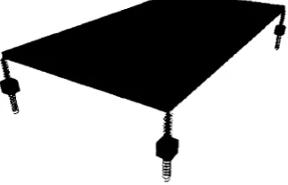
4.0 The quarter car lumped mass model and the litis m o d e l... 32
4.1 ADAMS half car m o d e l... 33
4.2 ADAMS full car m o d e l... 33
4.3 litis utility tr u c k ... 34
4.4 litis utility truck suspension u n i t ... 35
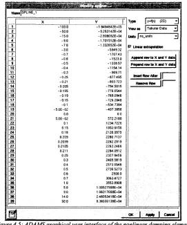
4.5 ADAMS graphical user interface o f the nonlinear damping e le m e n t... 36
4.6 ADAMS quarter car model o f l i t i s ... 37
4.7 ADAMS full car model o f l i t i s ... 37
4.8 Simulink block representation o f the LQR c o n tro ller... 38
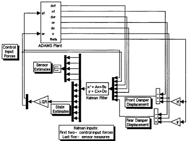
4.9 Simulink block representation o f the Kalman filte r... 39
4.10 Sem i-active, ideal skyhook damping switch block d ia g ra m ... 39
5.0 ADAMS Simulink interfacing configurations within S im u lin k ... 42
5.1 ADAMS quarter car model with the tire force in p u t... 42
5.2 Simulink diagram o f the tire force construction... 43
5.3 Block diagram for linmod function < filen am e> ... 43
5.4 litis full model o f the static export m e th o d ... 46
5.5 litis full model of the gravity export m e th o d ... 47
5.6 Linear litis full car model (no b u sh in g s)... 49
5.7 Nonlinear lumped mass half car m o d e l... 50
5.8 Linear lumped mass quarter car m o d e l... 50
5.9 Technique used to break algebraic loop for the nonlinear litis quarter car m o d e l... 51
6.0 Vertical displacement profile o f speed b u m p ... 53
6.1 Speed bump profiles for each com er o f the full c a r ... 53
6.2 Suspension com er notation o f full car m o d e l... 53
6.3 Sprung mass vertical acceleratio n ... 55
6.5 Suspension displacem ent... 56
6.6 Sprung mass vertical acceleration ... 57
6.7 Tire dynamic f o r c e ... 58
6.8 Suspension d isplacem ent... 58
6.9 Sprung mass vertical acceleration... 59
6.10 Tire dynamic f o r c e ... 60
6.11 Suspension displacem ent... 60
6.12 Sprung mass vertical acceleratio n ... 61
6.13 Tire dynamic fo r c e ... 61
6.14 Suspension displacem ent... 62
6.15 Pow er consumption o f active elem ent while traveling over speed b u m p ... 62
6.16 T ire lift off tracking function T L ... 63
6.17 Sprung mass v e lo c ity ... 64
6.18 Sprung mass displacem ent... 65
6.19 Unsprung mass v e lo c ity ... 65
6.20 Unsprung mass displacem ent... 65
6.21 Sprung mass vertical acceleratio n ... 66
6.22 Sprung mass roll acceleration ... 66
6.23 Sprung mass pitch acceleration... 67
6.24 Tire dynamic force o f com er 1 1 ... 67
6.25 Active control force o f com er 1 1 ... 68
6.26 Unsprung mass displacement o f corner 1 1 ... 68
6.27 Sprung mass vertical v e lo c ity ... 69
6.28 Suspension displacement o f com er 1 1 ... 69
6.29 Sprung mass vertical acceleratio n... 71
6.30 Sprung mass roll acceleration... 71
6.31 Sprung mass pitch acceleration ... 71
6.32 Tire dynamic force o f com er 1 1 ... 72
6.33 Suspension displacement o f com er 1 1 ... 72
6.34 Sprung mass vertical acceleratio n... 73
6.35 Sprung mass roll acceleration... 73
6.36 Sprung mass pitch acceleration ... 74
6.37 Tire dynamic force o f com er 1 1 ... 74
6.38 Suspension displacement o f corner 1 1 ... 75
6.39 Power consumption o f active elem ent while traveling over speed bump, corner 1 1 ... 75
6.40 Tire lift off tracking function TL o f com er 1 1 ... 75
6.41 Angular pitch v e lo c ity ... 77
6.42 Angular pitch displacem ent... 77
6.44 Displacement o f corner 1 1 ... 78
6.45 Sprung mass vertical acceleratio n ... 79
6.46 Force produced for the linear and nonlinear s p rin g ... 80
6.47 Force magnitude o f the passive nonlinear spring and the active ele m e n t... 80
6.48 Tire dynamic f o r c e ... 81
6.49 Suspension d isp lacem en t... 81
6.50 Sprung mass vertical acceleratio n ... 83
6.51 Tire dynamic fo r c e ... 83
6.52 Suspension d isp lacem en t... 84
6.53 Sprung mass vertical acceleratio n ... 84
6.54 Tire dynamic f o r c e ... 85
6.55 Suspension d isp lacem en t... 85
6.56 Power consumption o f active element while traveling over speed b u m p ... 86
6.57 Tire lift off tracking function T L ... 86
6.58 State o f the semi-active switch and the road disturbance versus tim e ... 87
6.59 Sprung mass v e lo c ity ... 88
6.60 Sprung mass d isp lacem en t... 88
6.61 Lower control arm angular v e lo c ity ... 88
6.62 Lower control arm angular d isplacem ent... 89
6.63 Sprung mass vertical acceleratio n ... 90
6.64 Sprung mass roll acceleratio n ... 90
6.65 Sprung mass pitch acceleratio n ... 91
6.66 Tire dynamic force o f com er 1 1 ... 91
6.67 Suspension displacem ent o f corner 1 1 ... 92
6.68 Sprung mass vertical acceleratio n ... 95
6.69 Sprung mass roll acceleratio n ... 95
6.70 Sprung mass pitch acceleratio n ... 95
6.71 Tire dynamic force o f com er 1 1 ... 96
6.72 Suspension displacement o f com er 1 1 ... 96
6.73 Sprung mass vertical acceleratio n ... 97
6.74 Sprung mass roll acceleratio n ... 98
6.75 Sprung mass pitch acceleratio n... 98
6.76 Tire dynamic force o f corner 1 1 ... 99
6.77 Suspension displacement o f com er 1 1 ... 99
6.78 Power consumption o f active elem ent while traveling over speed bump, com er 1 1 ... 100
6.79 Tire lift off tracking function TL o f com er 1 1 ... 100
6.81 Angular pitch p o sitio n ... 102
6.82 Angular velocity o f corner 1 1 ... 103
6.83 Angular displacement o f com er 1 1 ... 103
6.84 Sprung mass vertical acceleration... 104
6.85 Sprung mass roll acceleration... 104
6.86 Sprung mass pitch acceleratio n ... 105
6.87 Tire dynamic force o f corner 1 1 ... 105
6.88 Suspension displacement o f com er 1 1 ... 106
6.89 Sprung mass vertical acceleration ... 107
6.90 Sprung mass roll acceleration... 107
6.91 Sprung mass pitch acceleration ... 108
6.92 Tire dynamic force o f com er 1 1 ... 108
6.93 Suspension displacement o f com er 1 1 ... 109
A.0 Quarter car m o d e l... 123
A.1 H alf car m o d e l... 124
A.2 Full car m o d e l... 126
A.3 Full car l i t i s ... 132
1 0 0
i.e. 0 2 0
0 0 3
ADAMS - Automatic Dynamic Analysis o f Mechanical System
ARDC - University o f W indsor DaimlerChrysler Automotive Research and D evelopm ent Centre
ARC - Active Roll Control
CM - Sprung mass
DAE - Differential algebraic equations
DET - The determinant o f a matrix.
DIAG - Diagonal square matrix, its non-zero numerical values are listed in order o f appearance expressed as diag[l 2 3]
DRES - Defence Research Establishm ent Suffield
E.C.U. - Electronic control unit
EOM - Equations o f motion
GSTIFF - Gear Stiff integrator
LCA - Lower control arm
LQG - Linear quadratic guassian controller, the combination o f using LQR for the controller with the
Kalman filter to estimate the states
LQR - Linear quadratic regulator algorithm
L.V.D.T. - Linear voltage displacement transducer
nb - Number o f bodies
m - Sum o f the joint constraint equations
ODE - Nonlinear ordinary differential equations
RR - Ride rate
SP - Spindle
S & G Damping - Skyhook and ground-hook damping
S
y m b o l sa - Vehicle lateral dimension.
A® - Closed loop system matrix, it includes the plant and controller.
A - Plant matrix (n x n).
A - System matrix where states are the desired states o f the user. AeSt- System matrix (n x n).
A, - 111 conditioned plant matrix.
A 2 - Plant matrix in partitioned form,
b - Vehicle lateral dimension. B - Plant input m atrix (n x (ri+ r2)). B! - Control force input matrix (n x r^ . B2 - R oad displacement input matrix (n x r2).
B - Input matrix where states are the desired states o f the user.
Best- Input matrix o f control input force and sensor output measurements (n x (ri+m)). B, - 111 conditioned plant input matrix.
B 2 - Plant input matrix in partitioned form,
c - Vehicle longitudinal dimension. cgh - Ground-hook damper coefficient.
csky- Skyhook dam per coefficient.
cs - Semi-active damping rate.
cst - Strut dam per coefficient. C - Output matrix ((n+m) x n).
i) if full state feedback desired- an (n x n) identity matrix. ii) for measured outputs- an (m x n) matrix.
C - Output matrix where states are the desired states o f the user. C, - Output matrix where output is desired states.
Cest— Output matrix o f sensor output measurements and state estimates ((m+n) x n). Cs- Measured sensor outputs,
d - Vehicle longitudinal dimension. D - Output matrix ((n+m) x (ri+r2)).
D - Output matrix where states are the desired states o f the user. Dj - Output matrix where output is desired states.
Dest- M atrix o f size ((m+n) x (rj+m)). D s - M easured sensor outputs. E - Expected value,
f - V ector o f applied forces.
Fsky - Force generated from skyhook damper.
^desired - Desired force for the semi-active damper.
Fgh - Force generated from ground-hook damper.
Fmax - Maximum force from semi-active damper. Fmin — Minimum force from semi-active damper. Fs- Spring strut force.
FD- Damper strut force. Ft - T i r e force.
F s ( x o ) - Spring preload for the linear spring.
Fjnr- Linear spring force.
Fsc - Suspension force.
Tf 1
6
F (q,q,r)= _ e R - Vector o f applied forces.
n
g - Acceleration o f gravity, 9.81m/s2.
g - Set o f DAE describing a general multibody system.
G - State matrix corresponding to process noise, h - Height o f road profile.
h — Integration step size.
H - Output matrix corresponding to process noise. I - Identity matrix.
Iy - Inertia about y-axis.
Ix - Inertia about x-axis.
Iz - Inertia about z-axis.
J - Quadratic cost function.
J - Jacobian matrix o f g.
J - Generalized inertia matrix, expressed in the local body reference frame reference frame.
k - Step size/sample rate.
ktin.- Radial spring rate stiffness o f tire. kspsn- Suspension spring stiffness.
klqr- The optimal gain matrix from LQ R solution, (rj x n). ks- Strut spring stiffness.
k, - Tire radial stiffness. K - Full state feedback gain.
KeSt- M atlab object consisting o f state-space matrices that describe the Kalman filter.
lf - The horizontal distance between the front axle and the center o f gravity.
lr - The horizontal distance between the front axle and the center o f gravity.
L - Proportional error feedback gain for state estimator. nispmg- Sprung mass.
niuspmg- Unsprung mass. ms- Sprung mass. mu - Unsprung mass.
m ,- Total mass o f the vehicle body (excludes the mass o f the unsprung mass).
m - Sum of the joint and motion constraint equations, equals the number o f Lagrange multipliers.
M - Generalized mass matrix.
n - Vector o f applied torques.
nb - Number o f bodies in the system.
nj - Number o f joints in the system.
p - M atrix o f the body position o f a rigid body.
P - Generalized momentum.
P - Riccati equation solution matrix. Pe - Riccati matrix for Kalman filter,
q - M atrix o f the generalized coordinates o f a rigid body.
Q - W eight matrix, is a positive definite or semi-definite matrix (n x n). Qn - Covariance o f process noise.
Q (q ,q ,r)e R 6 - Generalized forces acting on the body, obtained by projecting the applied force F on the
generalized coordinates, Q = [ ( lT ) Tf (n'*)Tn ] T
R - W eight matrix, is a positive definite or real symmetric matrix (rj x rj). R n - Covariance o f m easurement noise,
t - Time.
TL - Tire lift o ff tracking function measure.
T - Transformation matrix relating body angular velocity in the local coordinate system with that defined. in the generalized coordinate system,
u - Unconstrained control force input (rj vector),
u* - Input, from both control and road.
da
- Dependant variables,u - Vector o f the body translational velocity.
U k - Inputs to plant model in discrete solver model,
v - Damper velocity.
v
- Measurement noise.vp- Velocity o f point o f application P o f the external force F. <5v - Independent variables,
w - Road displacement input (r2 vector).
Wspmg - Undamped sprung mass natural frequency. Wunspmg - Undamped unsprung mass natural frequency.
w - Process noise.
Si - Vector o f the body angular velocity, expressed in the local body reference frame.
W - Road input frequency.
x - State vector, the minimum set o f independent variables that fully describe the system (n vector). x0 - Set point/operating point.
Xjctuai- Actual/current value o f the states. ^desired - Desired value o f the states.
x - State error, difference between actual and estimated state. x - Estimated state.
xi - Set o f independent variables. x2- Set o f dependent variables.
xA - Set o f independent states in the ADAMS model.
x D - Damper displacement.
^actual - Actual state-space variable value.
^desired - Desired state-space variable, for this study this value is zero.
X - States desired by user.
xu- Undesired state space matrix.
Ax - Spring deflection.
x - Distance between the strut mounting points.
X - Displacement in the x direction, y - User defined output ((n+m) vector),
y - Estimated output.
Y - Displacement in the y direction. Y - Solution vector, Y =[q,q,k]T .
AY - Correction o f Y. Y* - U ser specified set-point.
z - State variables o f controller in cosimulation mode. zu - Unsprung mass absolute vertical displacement. zs - Sprung mass absolute vertical displacement. z l 1 - Vertical displacement o f com er 11. z l2 - Vertical displacement o f com er 12. z21 - Vertical displacement o f com er 21. z22 - Vertical displacement o f com er 22. Zroad - Road vertical profile.
zt - Tire vertical movement.
z - Complex constant vector.
zcm - Displacement o f sprung mass in z direction.
e - Array o f the body orientation o f rigid body. P - Rotation about the z-axis.
£ - Time derivative o f e.
X e R m - Lagrange m ultiplier array. The num ber o f multipliers is equal to the num ber o f jo in t constraint
equations (m).
T - Angular momenta.
P p- Projection operator.
P R - Projection operator.
iff,6,<l>- Third, first and third Euler angle sequence o f rotation.
a,/3o,/3s - Gear integration constants.
a - Complex constant vector.
O - Algebraic constraint equation.
<!>„ - Constraint equation as a function o f dependent variables. O v- Constraint equation as a function o f independent variables. 0 - Angle.
1 I
n t r o d u c t i o n1.0 Problem Synthesis
A passenger automobile suspension is a compromise between ride and handling and as such it is
the aim o f the vehicle dynamicist to find settings that give the best o f both worlds. Since passive suspension
has existed throughout the age o f the automobile, much is known o f the system and engineers today are
very good at extracting the m ost performance from it. In fact it is commonly thought that the performance
o f today’s passive suspension has little more improvement left in it. This, com bined with a highly
competitive autom otive market, with hard to please consumers, has sent companies searching for alternative
solutions to the conventional system.
As defined by W ong {23} ride is concerned with the sensation or feel o f the passenger in the
environment o f a moving vehicle. Problems arise mainly from vibrations o f the vehicle body, induced by
sources such as aerodynamic forces and vibrations from the powertrain, drivetrain and road. As stated by
Hrovat {31}, vertical ground input disturbances caused by road roughness are the m ost relevant for ride
studies. Handling, on the other hand, deals with the vehicle’s response to steering, braking and
environmental inputs. In part handling is a measure o f the ability to manoeuvre turns since this deals mostly
with the vehicle’s response to inertial body input forces. The main criteria for optimizing the dynamics o f a
vehicle are:
• Body motion caused from road surface irregularities.
• Body motion caused from road inputs, aerodynamic loading and inertial forces.
• Road holding related to the contact force between the tire and road surface (through controlling wheel
motion).
• Suspension travel, which is limited by the packaging restrictions o f the vehicle.
• Maintain directional stability during manoeuvres.
An active suspension is better able to find a compromise between these conflicting requirements
and as such can offer greater performance than a passive suspension. However, even with the most
sophisticated system, no suspension can simultaneously optimize each o f the above criteria since they are
all coupled. Although the concept o f active suspension has existed since the 1950’s when companies like
-Citroen and W estinghouse experimented with prototypes, the technology has yet to fully break into
production for different reasons.
This research simulates active suspension vehicles using various methods; it carves out a process
for developing vehicle models in which the characteristics o f such a system can be evaluated and optimized.
From such an analysis, problems in the initial design phase can be identified before prototyping and so
money and tim e can be saved in development, helping to further usher this technology into the automotive
market.
1.1 Ride versus Handling 1.1.1 Model Description
A vehicle is a complex multi-degree o f freedom system that requires sophisticated multibody
dynamic algorithms to describe its behaviour. However, to reveal its fundamental response and limitations,
a simple lumped mass model o f a quarter o f the vehicle may be considered; in this way the following
discussion will be simpler to outline.
Sprung Mass
Strut Unit
Unsprung Mass
Tire Spring- •Road Profile Input
Figure 1.0: Quarter car model
From Figure 1.0, the sprung mass represents the vehicle body; in this model it is roughly one
quarter the weight o f the entire body, while the unsprung mass represents the mass o f one wheel unit. Here
the strut unit contains both the suspension spring and damper; it provides the link betw een the two masses.
At the same time the tire spring represents the radial stiffness o f the tire with negligible damping (as
assumed by m ost ride studies). The road input is specified at the end o f the tire spring in the form o f a
vertical displacement and since both masses are constrained to only move vertically, the system has two
degrees o f freedom system.
During operation, it is the suspension spring that absorbs most o f the disturbance movement, while
the damper dissipates this energy input from the road. O f the variables that affect the vehicle response, the
damper and spring rate o f the strut unit are two that the dynamicist has direct control over; their chosen
parameters contribute to the conflict between ride and handling.
1.1.2 Spring Conflict
W hen solving the equations o f motion for the quarter car model, since damping is typically small,
Ch a p t e r 1. In t r o d u c t io n
w„ RR (
1
.0
)vv„.
R R :
spsn tire
unsprog
f k spsn *k tire ^
k.m„ + k ti„
y spsn tue
( l . l )
(1.2)
From these equations, the suspension spring rate is related to both natural frequencies and is the
only value in the equations that the dynamicist has control over. Due to the difference in mass, the natural
frequency o f the unsprung mass is an order higher than the sprung mass (around 10Hz and 1Hz
respectively). W hen the unsprung mass becom es excited by the road the sprung mass becomes excited by
the unsprung mass. As a result, for high frequency inputs when the unsprung mass is vibrating near its
natural frequency, the sprung mass is mostly unaffected, since its resonant frequency is much lower.
However for low frequency inputs, disturbances are passed by the wheel to the body, even amplified at
times.
In examining the characteristics o f a typical random road profile the vertical acceleration intensity
increases with road frequency. As a result, minimizing the natural frequency o f the sprung mass decreases
the intensity o f its response when excited and results in a better ride. This implies that the strut spring
should be as soft as possible.
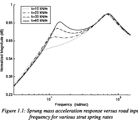
Another way to see the effects o f the suspension spring rate on the sprung mass is by considering
the frequency response plot+ o f the sprung mass acceleration o f Figure 1.1. Frequency plots generate the
sinusoidal response amplitude to a vertical sine wave road profile o f varying frequency. As shown, the
softer the suspension the lower the acceleration levels o f the sprung mass, especially in the area o f its
natural frequency. However the softness o f the strut spring is limited by the am ount o f space in which the
suspension can move within - both while the car statically sits and when it encounters road disturbances.
*Notice: All graphs in this study are ‘normalized’ by dividing the y-axis values by the maximum value attained.
-k«10 kN/m k -2 0 kN/m k=30 kN/m k - 4 0 kN/m 0.85
S'33 ©
T33
E
0 5
<0
0.69
2
0.54
fO £ o
Z 0.38
0.23
F re q u e n c y (ra d /se c )
Figure 1.1: Sprung mass acceleration response versus road input frequency fo r various strut spring rates
Although a softer suspension produces less sprung mass motion, it also leads to deterioration in
handling due to a loss o f tire grip. W hen the vehicle performs a cornering manoeuvre the sprung mass shifts
to the outside tires increasing the normal tire loading on the outside tires and decreasing it on the inside.
The generated lateral tire force is related to the normal tire load, yet at a decreasing rate as illustrated in
Figure 1.2. As such, the more the vehicle rolls the less lateral tire grip is produced from the combined
outside and inside lateral tire force. Hence for handling purposes stiff springs should be used.
Simplified Tire Real Tire 0.9
2 0 -4
0.2
0.2 0.3 0.4 0.5 Normalized Normal Tire F o rce
0.7 0.8 0.9
Figure 1.2: A typical relationship between the tire lateral force and vertical force
For ride manoeuvres, softer springs lead to greater wheel movement which will increase the
fluctuation in tire force. This is confirmed in Figure 1.3, which shows the frequency response o f the tire
force. For road input frequencies near the unsprung mass resonant frequency, a softer suspension leads to
Ch a p t e r 1. In t r o d u c t io n
k « 1 0 kN/m k - 2 0 kN/m k - 3 0 kN/m k - 4 0 kN/m 0.91
m33 a>
T3
3
'E
OT
(0
0.83
2
0.74
(0 E
o Z
0.65
0.56
F re q u e n c y (ra d /se c )
Figure 1.3: Tire force response versus road input frequency fo r various strut spring rates
1.1.3 Damper Conflict
The ideal damping coefficient depends on the natural frequencies o f the system and the road input
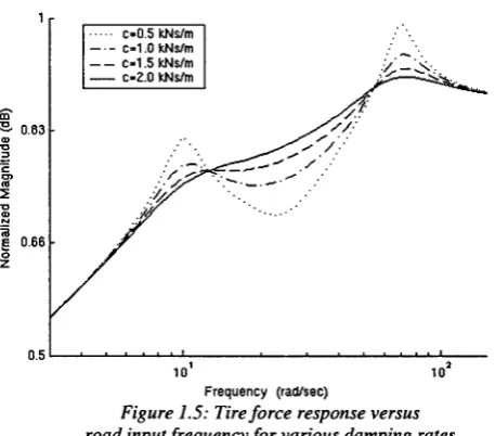
frequency and so it continuously changes as the vehicle operates. In looking at the frequency response o f
the body acceleration in Figure 1.4 for different damping rates, for input frequencies around the natural
frequencies high damping is best, yet at all other frequencies low dam ping is preferred. A similar pattern
emerges for the tire force frequency response in Figure 1.5, high dam ping is ideal near the body and wheel
natural frequencies with low dam ping ideal everywhere else in minimizing tire deflection.
c -0 .5 kNs/m c -1 .0 kNs/m c -1 .5 kNs/m c -2 .0 kNs/m 0.85
0.69 / / ;
S 0.54
0.38
0.23
F re q u e n c y (ra d /se c )
Figure 1.4: Sprung mass acceleration response versus road input frequency fo r various damping rates
-c» 0 .5 kNs/m c -1 .0 kNs/m c - 1 .5 kNs/m
c - 2 .0 kNs/m -S':
T3
a>
T3
0.83
c
o> 01 2
T3
CD
73 § 0.66
o
2
0.5
10
F re q u e n c y (ra d /se c )
Figure 1.5: Tire force response versus road input frequency fo r various damping rates
1.2 The Active Solution
A way o f addressing the above conflicts is a suspension with a variable stiffness that changes
according to measured parameters such as body movement, spring displacement, steering angle, etc. Using
feedback from sensors, an electronic control unit (E.C.U.) finds the optimal action that produces the best
combination o f ride and handling. An active elem ent within the suspension then generates the action that
the E.C.U. deems optimal.
1.2.1 Fully-Active Suspension
A fully-active system typically makes use o f hydraulic power. A pump, driven by a belt from the
engine supplies a source o f oil. As the vehicle operates, sensors throughout the vehicle send data to the
E.C.U., which determines the optimal suspension force. The controller then sends a current/voltage to the
power valve which regulates the flow rate o f oil to enter/exit the actuators. In the final phase, the double
acting piston actuators convert the pressure difference betw een their upper and lower chambers into a net
force on the suspension. Other elements are required such as accumulators, relief valves, throttle valves, etc.
Fully-active suspension differs from passive and semi-active suspension in its ability to inject
energy into the vehicle. Only a high-bandwidth active system will be considered for this project; it is
defined by having the capability o f controlling road frequency inputs as high as 25Hz. This system typically
uses a spring to carry the static weight o f the vehicle along with a double acting hydraulic actuator placed
parallel to it. Since it controls both sprung and unsprung mass resonance motion, the requirements and
demands o f the system components are relatively high. Peak power requirements in the range o f 4 to lOkW
have been quoted in the past, corresponding to an increase o f 10-20% in fuel consumption, with the system
hardware adding anywhere from 49 to 136kg.
1.2.2 Semi-Active Suspension
A semi-active suspension varies the rate o f energy dissipation based on a closed loop feedback o f
Ch a p t e r 1. In t r o d u c t io n
in parallel with a conventional spring. The system is relatively simple, affordable, and quick (response
times o f 30 to 150ms) with the promise o f increased ride performance. As a result, it is seeing an increased
presence in production cars.
Three commonly used methods to alter the damping coefficient are: on-off, continuously variable
and rheological fluid damping. The first method switches between discrete states o f damping resistance
through the use o f motor/solenoid driven internal valves that switch between different orifice areas.
Continuous damping is similar to the first method except that it now has the ability to continuously vary the
orifice area between a maximum and minim um value. In the last method no moving parts are used to vary
the damping coefficient, instead the viscosity o f the dam per fluid is altered in response to the intensity o f an
applied energy field.
1.2.3 System Problems
To this day few fully-active suspension vehicles have made it to production. The main reasons
include, but are not limited to, the increased power consumption and response time o f the suspension, the
reliability and serviceability o f the hydraulic system, increased cost, added weight and achieving system
robustness.
Also, over the years designers have become very good at dealing with the ride/handling trade-off
and extracting performance from the passive suspension. Designs used to increase passive perform ance
include:
• nonlinear spring, damper and bushing stiffness
• stiffer body structures to maintain a more accurate suspension geometry
• low profile tires with high lateral stiffness
• anti-roll bars and anti-dive suspension geometry to resist roll and pitch
• lighter unsprung components
• more complicated suspension geometry
As a result consumer dem and for a better suspension has to this day not been strong, contributing
to the reluctance o f implementing active systems.
1.3 Software Interfacing
M ost engineering systems are multi-domain, where the distinct sub-systems are difficult to
simulate in a single software program, requiring many simplifications and inaccuracies. In a fully-active
suspension three distinct domains exist: the vehicle, the E.C.U. and the hydraulic system. To properly
model all three domains and capture how they interact with the rest o f the system, software interfacing
techniques are suggested.
In short, different software programs are connected to one another to solve different aspects o f the
same problem. This interfacing allows each sub-system to be modeled in its natural software domain which
more accurately captures the dynamics o f the sub-systems. W ith the tools used in this study, the user has the
option o f either having the solver o f each software integrate its ow n model (known as discrete
-mode/cosimulation) or letting the integrator from the control software solve the entire system (known as
continuous mode).
Although the above methods solve nonlinear multibody systems, a linearized version may be
exported to the controller software. Linear models, although not as accurate, gives the user access to tools
such as frequency response plots and allow eigen analysis to be performed. These linearized versions are
also sometimes necessary for designing controllers.
Software interfacing is relatively new and unused for active suspension simulation (at least in
academia) but should gain in popularity as software developers refine the interfacing capabilities o f their
products.
1.4 Objectives
The objective o f this research is to determ ine the feasibility o f synthesizing procedures to simulate
active suspensions by interfacing different software programs. Attention is focused on the ride response o f
the vehicle and so this research does not evaluate the handling behaviour o f active suspension. It should
also be emphasized that focus is not on trying to design a road-worthy control algorithm with an ultra
detailed vehicle model, but rather on perform ing a preliminary evaluation on the usefulness o f the
simulation techniques developed.
M ore specifically to:
• Implement a quarter and a full car model o f a generic lumped mass passenger vehicle and o f the
Bombardier litis utility truck.
• M odel the vehicle in ADAMS, the E.C.U. in Matlab/Simulink.
• Use algorithms related to skyhook dam ping for the semi-active suspension.
• Use linear optimal control techniques (LQR controller) to design the fully-active controller.
• Implement a Kalman filter to estimate the system states for the LQR.
• Add suspension bushings to the full vehicle litis model for increased realism.
And to compare:
• The differences o f the various procedures developed and the available solver modes.
• Explore the differences o f using linear and nonlinear models o f the vehicle.
• The different vehicle models.
• Compare passive, semi-active and fully-active suspension.
All research is conducted at the Daim lerChrysler Automotive Research and Developm ent Centre
2 L
it e r a t u r eR
e v i e w2.0 Active Suspension A pplication
2.0.1 Active A nti-R oll B ar
Anti-roll bars are laterally placed tubes that link the left and right suspension together through drop
links to the suspension control arms (Figure 2.0). When both wheels move up the same amount, the roll bar
rotates about its lateral axis and exerts negligible force on the wheels. However when the vehicle rolls, the
left and right control arms rotate relative to one another and as a result the roll bar twists and exerts an
opposing force to reduce body roll.
Spindle/Hub
Figure 2.0: Configuration o f a typical fr o n t suspension
Active anti-roll bars have entered production vehicles with the ability to vary its torsional stiffness.
In BM W ’s Dynamic Drive system, the active anti-roll bar consists o f two halves that are connected through
a hydraulically operated swivel motor. The motor, through transforming hydraulic pressure into a
stabilizing counter-torque resistance, varies the stiffness o f the roll bar according to the lateral acceleration
o f the vehicle. When the acceleration is negligible, the system depressurizes so as to not influence the roll
dynamics. In this way the understeer and oversteer characteristics o f the vehicle can be modified in
response to the lateral acceleration o f the body by varying the front and rear roll resistance. BMW claims
that for lateral accelerations from up to 0.3g, no roll occurs and for an acceleration o f 0.6g an 80%
reduction is achieved.
TR W ’s system named Active Roll Control (ARC) varies the stiffness o f the roll bar by replacing
one anti-roll bar drop link with a computer controlled linear actuator that uses hydraulic pressure to apply a
-resisting force. The actuator is driven by the power steering pump and is controlled by a servo-valve in
response to sensor outputs. Lateral accelerometers, a steering angle sensor and other sensors determine the
roll force and directs a control valve to apply a counterbalancing force to the sway bar. TRW claims that the
system eliminates body lean up to 0.4g o f lateral acceleration, which translates into moderately hard
cornering. Above this level the system allows some body roll to warn the driver o f an im pending loss o f tire
traction.
2.0.2 Variable Geometry Suspension
W ith this system the geometry o f the suspension is altered to vary the suspension stiffness in
response to vehicle motion. Past research is sparse compared to active suspension systems and the concept
is relatively new. The 1965 Velocette Thruxton motorcycle is one of the earliest production examples; it
allows the driver to manually adjust the top m ount location o f the spring. Experim ental cars that
automatically vary the strut or leaf spring m ount locations have also been built with success. A main focus
in their design is having the actuator apply forces perpendicular to the main suspension forces, minimizing
the energy needed to change the mount position.
In another design, M inaker {15} moved the body attachment points o f the lower control arms
through hydraulic or electric actuators. In this manner the location o f the vehicle roll center relative to the
vehicle center o f gravity is controlled and changes the handling characteristics o f the vehicle. Under closed
loop control the system consumed a peak pow er consum ption o f under 100W with a reduction in roll and
heave during cornering manoeuvres. Overall the concept showed potential for future application.
2.0.3 Rheological Semi-Active Damper
A rheological fluid exhibits a change in flow when an energy field is applied to it since the
particles, that are randomly dispersed, group together to follow the path o f the applied field. As the fluid
flows the particle bonds are broken only to be reform ed to follow this energy field while absorbing energy
in the process. Since the tendency to bond varies with the strength o f the field, the level o f energy
dissipation is controllable. These fluids are used within dampers to continuously vary their viscosity
according to a control input signal that in certain designs change according to the road input frequency.
Additional information on this topic may be found in {37}.
2.0.4 Active Body Control
Currently used in Mercedes road cars, the Active Body Control (ABC) system is a fully-active
hydraulic suspension system that relies on thirteen vehicle sensors. As M erker et al. {34} explains, at each
com er o f the vehicle a hydraulic actuator is connected in series with the top o f the strut spring. By
extending/retracting the cylinder the spring preload changes and varies the suspension stiffness. Since the
system is low-bandwidth, meaning it’s only effective for frequencies ju st greater than the sprung mass
vibration mode, it requires little energy compared to a high-bandwidth system. ABC uses a system pressure
Ch a p t e r 2 . Li t e r a t u r e Re v ie w
2.0.5 Lotus Active Suspension
In 1980 a joint venture formed between Cranfield Institute o f Technology and Lotus Engineering
to develop high-bandwidth hydraulic active suspensions for the Lotus Esprit and the Lotus Form ula One
race cars. The purpose was to address the high aerodynamic loading on ground effect racing cars (up to 3
times its static weight) by minimizing the weight transfer on the tires. The system was first fitted to the
Esprit with the E.C.U. aimed at controlling the hydraulic pressure and the car attitude with the capability o f
altering the damping, the body attitude and its rate o f change. Additionally, the roll stiffness distribution
was adjustable and the modes o f vibration could be separated/decoupled.
Road induced dynamic loads transmitted through the tires were around half those o f a passive
system and an improvement in handling in the order o f 10-20% was claimed. The road version o f the
system was driver controllable, allowing the passengers to completely eliminate body motion during bumps
and transient manoeuvres. The system pressure was in the neighbourhood o f 17.2MPa with a response time
o f approximately 3ms at a cost o f 4-7kW and 20-45kg in mass. In spite o f the increased weight the F I car
was noticeably quicker than its passive version since cornering speeds increased by 10%. M ore information
on the program is available from {45}, {49} and {50}.
2.0.6 Citroen Hydraulic Suspension
A pioneer in active suspension, Citroen has a long history o f offering hydraulic suspension. As
summarized by M erker et al. {34} its current ‘hydractive’ system uses six accumulators: one at each corner,
one between the front wheels and one between the rear wheels. Conventional springs and dampers are
therefore not needed as their function is replaced by the accumulators. Suspension stiffness is varied by
switching the central accumulators in and out o f the hydraulic circuit which changes the total volume o f
fluid and gas in the system (less gas-more stiff). In addition all four suspensions are interconnected by the
high pressure fluid that further smoothes the ride. Another important characteristic o f the system is that the
hydraulics has a variable effect - it becomes harder as the loads are increased.
2.0.7 litis Active Suspension
Commissioned by the Defence Research Establishm ent Suffield (DRES) in the late eighties, a
fully-active hydraulic suspension system was fitted to the Bom bardier litis utility jeep by researchers from
Queen’s University. The system used hydraulic servo-actuators with a hydraulic system pressure o f
20.6M Pa and an 80386DX-20M Hz IBM-PC compatible microcomputer for the E.C.U. Tests indicated that
simultaneous improvements in ride and handling were achieved.
Another feature o f the truck was its preview system. Using electronic ultrasonic sensors, the road
profile at the front bum per was measured and the information sent to the main controller. The strategy was
to have the active system anticipate and act as the vehicle encountered road irregularities, rather than
having the suspension react after the disturbances occurred. It has the added advantage o f reducing the
overall energy consumption. For more information refer to {33} and {44}.
-2.1 Virtual Active Research
Unless stated, the following studies ignore the dynamics o f the hydraulics, assuming that the desired force
calculated from the controller is the force applied to the suspension with no tim e delay.
2.1.1 Linear Quadratic Regulator (LQR)
Thompson {43} generated a two degree o f freedom lumped mass quarter car model. The LQR
weighting function consisted o f the mass velocities and the tire and suspension dynamic deflections. Results
to a unit step input indicated a reduction in body overshoot at the cost o f the unsprung mass motion. In
comparing the eigenvalues, the LQR system increased the sprung mass dam ping and decreased the
unsprung mass damping, this explained why the body settled more quickly. The author concluded that the
active suspension was better in practically all respects predicting that further refinem ent o f the controller
weighting matrices and the addition o f dynamic vibration absorbers would im prove the unsprung mass
oscillations.
As a bridge between chassis models that can perform nonlinear handling m anoeuvres and control
design studies, H aycock {30} looked at a two degree o f freedom quarter car model which incorporated the
geometry o f a short long arm suspension. The author conducted a ride study with a ramp road input by
implementing a full state feedback LQR controller and compared it to a passive suspension. Although
encouraged by the ride response, it was noticed that depending on the weights used, the solution still
contained an inherent compromise o f vehicle response. This led the author to suggest a frequency
dependent compensation controller be used since the required response depends on the changing conditions
and road disturbances.
Aimed at analyzing the effects o f changing suspension parameters, road disturbance and seat
position, an eight degree o f freedom lumped mass full car ride model was created by Bouazara et al. {25}.
A fully-active system was implemented using the LQR algorithm and com pared with a semi-active and
passive suspension. Here the weight function included the body accelerations, the suspension deflection and
wheel velocity and was weighted most heavily towards the suspension displacement. The wheel and sprung
mass velocities were hardly weighted. As the authors state, the final weighting values were chosen for a
good trade-off between comfort and road holding capability. The fully-active suspension was able to most
o f the tim e give a slightly superior response in both sprung and unsprung m ass motion for a double bump
road input (note: the LQR gain used was not aggressive). In addition the semi-active vehicle response
rivalled that o f the fully-active system giving a slightly worse performance.
Hrovat {31} reviewed the application o f LQR applied to various vehicle models. It is claimed that
for this controller, either ride or handling can be improved by choosing the weighting matrices accordingly.
He states that the full advantage o f active suspensions stems from adaptive tuning/gain scheduling o f the
controller parameters depending on the driving conditions. A situation is suggested where if the steering
and wheel position and lateral acceleration sensors indicate straight line operation o f the vehicle, then the
Ch a p t e r 2 . Li t e r a t u r e Re v ie w
As for nonlinear control, Hrovat {31} stated that for many operations a linear control system is
appropriate as suggested by past empirical validations. The shortcomings o f such a controller are seen
during situations which amplify discrete disturbances such as when the suspension bottoms out due to
potholes or speed bumps. H e supports an algorithm in which a linear controller is used for normal operation
and switches to a nonlinear scheme for discrete event disturbances.
2.1.2 Linear Quadratic Gaussian Regulator (LQG)
Sharma et al. {39} addressed the requirements o f full-state feedback for using an LQ R algorithm
with a quarter car model. They suggested incorporating a Kalm an filter to estimate the immeasurable states
and compared the model to one without the filter. Available measurements were assum ed to consist o f
suspension deflection and body acceleration which were used as inputs to the Kalm an filter. Although a
slight degradation was noted with the Kalman filter, the authors were pleased with the results. Also
encouraging was when the vehicle traversed a road o f different roughness and speed than the one used to
tune the controller. Performance was virtually maintained, leading the authors to state that there was no
need to implement an adaptive time varying estimator.
Taghirad et al. {42} taking passenger acceleration as an indication o f ride com fort used a half-car
model that incorporated the seat dynamics with an LQ G algorithm. Despite a random road profile, the state
estimates followed the true states quite closely, while assuming a typical sensor arrangement that measured
suspension travel and passenger bounce. In addition the authors found that their model decreased body
acceleration while producing tire forces on par with the passive system.
2.1.3 Semi-Active Control
In the now classic paper {26} by Karnopp et al., skyhook and semi-active damping was proposed
to increase the ride o f a vehicle suspension. The ideal skyhook damper scheme was synthesized for a one
degree o f freedom model by connecting a dam per from the mass to an inertial reference so that the damping
was proportional to the mass absolute velocity. W hile the conventional damper reduces the relative velocity
between the sprung and unsprung mass, effectively stiffening the suspension when a soft suspension is
desired, the skyhook dam per reduces the absolute body motion.
Karnopp et al. {26} theorized that a practical active system that approximated the unrealistic
skyhook damper configuration would perform better than a passive suspension. They went on to devise
such a system that switched between high and zero dam ping force for an active strut elem ent whose power
was restricted to being dissipative. Through simulation it was shown that this semi-active system had a
performance intermediate to the passive and ideal skyhook damper, yet required less pow er and complexity
than a fully-active system.
A shortcoming o f the work by the previous study was that with a skyhook damper, the unsprung
mass was not damped, leading to a degradation o f tire forces. Valasek et al. {46} addressed this issue with
a quarter car model by adding a damper that connected the unsprung mass with the ground, known as a
ground-hook damper. Although conceived to minimize road damage from trucks, the authors concluded