Performance Analysis of Different Slotted U, Half U, π
and Half π Microstrip Patch Antennas for LTE
Application
Prachi
M.Tech student DIT, University, Dehradun
Brajlata Chauhan
Uttarakhand Technical University, Dehradun UK (India)
Manish Jaiswal
M.Tech student DIT, University, Dehradun
ABSTRACT
This paper presents different slotted structures such as U-slot, half U-slot, half π-slot and π-slot to achieve the dual band characteristics of the antenna etched on a glass epoxy
substrate (εr= 4.3) is suspended over the ground plane with an
air gap for all slotted structures [1-2]. A comparative analysis has been made for the U and half U, π and half π designs are proposed by reducing area to 50% and increasing the substrate thickness (air gap).It was found that performances of half U slot MSA and half- π slot MSA are comparable to U- slot MSA and π Slot MSA respectively at the resonant frequencies 0.9 GHz and 1.1 GHz, which is desired for LTE band (0.7-3.5 GHz)application .The simulation analysis of all slotted antennas conclude that π slot has comparatively better performance in comparison to all.
Keywords
HFSS (High Frequency Structure Simulator), MSA
(Microstrip patch antenna), dB (decibel), LTE (Long Term Evolution)
1.
INTRODUCTION
Antenna is used to transform RF signal, travelling on a conductor, into an electromagnetic wave in free space maintaining the same characteristics regardless if it is transmitting or receiving. This shows its reciprocal property. In many wireless applications, dual band antennas are of interest that uses two different frequency bands for transmitting and receiving. Dual band operation is achieved by manipulating the fundamental resonant mode and one of its higher order modes. The proposed analysis shows us that all the structures give dual band operation in frequency band of 0.7-3.5GHz. By taking a single patch with a U-slot or parallel slots due to the creation of different current paths on the patch, additional resonant modes are excited.
The slot antennas are popular now a days because of its size, design simplicity, robustness, adaptable to mass production using PCB technology and can be cutout of whatever surface it is to be mounted .In this work without using size reduction techniques U slot MSA is discussed and half u slot MSA gives 50% reduction in area along the line of symmetry. Both U slot and half U slot loaded RMSA[3-4] are compared having improvement in the return loss, VSWR, gain and directivity .The slots are cut to reduce resonance frequency by increasing path length of surface current .If resonance frequency,
Slot and patch are close to each other, and then broad bandwidth is achieved. All the MSAs were analyzed using HFSS software.
In section-2 of this paper we had given antenna geometry and parameter, in section-3 simulation results and in section-4 conclusion is shown.
2. ANTENNA GEOMETRY AND
DESIGN
2.1 U- slot and π- slot
For U slot [5] and π slots, the antenna geometry is shown in fig.1 and fig 2 respectively. Both the slots are printed on glass epoxy substrate (with dielectric constant=4.3) having h=0.159cm.The substrate is suspended over ground plane with an air gap of 1.7 cm .In this paper MSAs are loaded with different slots that affects one resonant mode with another and in this way dual band operation is obtained .
Figure 1 U-Slot Figure 2 π-Slot
2.2 Half U and Half π slot
For half U slot and half π slot the proposed antenna geometry is shown in fig .2.Both the slots are etched on same substrate with reducing the area of the patch along the symmetry of the line and increasing the height of air substrate. The substrate is suspended over ground plane with an air gap of 2.0 cm. By optimizing various parameters such as arms of slots, width of slot and feed point location, required dual band operation is achieved.
Figure3 half π Figure4 half-U
Volume 86 – No 18, January 2014
Table1.Parameters
By using the basic equations for designing Microstrip patch antenna we calculated the effective refractive index as.
1. Effective Dielectric constant:
Where, h = height of dielectric substrate w =width of patch
3. SIMULATION RESULT
The simulation is done using Ansoft HFSS (14.0). Different parameters are analyzed like return loss (S11), VSWR, gain, directivity etc. Each parameter is analyzed below as:
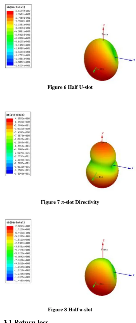
3.4 Directivity
: Directivity for all the antennas is shown in figure (5-8). Directivities for all antennas is summarized as in table 2 and shows that directivity (dB) of U-slot & π-slot are comparatively better than all.Table 2. Directivity
Band Freq(GHz) U- Slot Half
U-Slot
π slot Half π
slot Ist &
2nd
[image:2.595.50.542.37.772.2]0.9 & 1.1 4.3 2.5 4.3 2.5
Figure 6 Half U-slot
Figure 7 π-slot Directivity
Figure 8 Half π-slot
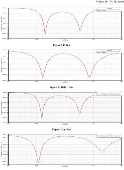
3.1 Return loss
We have used only one feeding technique in all antenna designs (probe feed) and the S11parameters (input reflection coefficients) are summarized as in table 3. The graphs in figures (9-12) verifies the performance of slotted antennas to a great extent and shows that Half U-slot and half π-slot which are obtained after reducing the area (up to 50%) of U- slot and π-slots respectively are comparable.
Table 3. Return Loss Parameters U- slot Half U
slot
Half
π slot π slot
Length(ground) 13.5 13.5 13.5 13.5
Width(ground) 15 7.5 7.5 15
Length(Patch) 7.0 7.5 7.5 7.0
Width(patch) 4 2.0 3.0 6.0
Slot thickness 1.0 1.0 1.0 1.0
Feed (fy,fx) 0.8,0 0.8,0 0.8,0 0.8,0
Airgap 1.7 2.0 2.0 1.7
Substrate Thickness
[image:2.595.310.540.67.613.2]Figure 9 U Slot
Figure 10 Half U Slot
[image:3.595.85.514.46.634.2]Figure 11 π -Slot
Figure 12 Half π -Slot
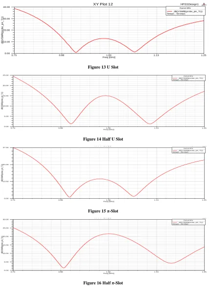
3.2 VSWR
All the results of VSWR are shown in Figure (13-16).
All the simulated results show that VSWR for each antenna lies in the range between1 to 2.
0.75 0.88 1.00 1.13 1.25
Freq [GHz] -30.00
-25.00 -20.00 -15.00 -10.00 -5.00 0.00
dB(S
t(p
ro
be
_p
in
_T
1,
pro
be
_p
in
_T
1))
HFSSDesign1
XY Plot 10 ANSOFT
Curve Inf o dB(St(probe_pin_T1,probe_pin_T1)) Setup1 : Sw eep1
0.75 0.88 1.00 1.13 1.25
Freq [GHz] -25.00
-20.00 -15.00 -10.00 -5.00 0.00
dB(S
t(p
ro
be
_p
in
_T
1,
pro
be
_p
in
_T
1))
HFSSDesign1
XY Plot 5 ANSOFT
Curve Inf o dB(St(probe_pin_T1,probe_pin_T1)) Setup1 : Sw eep1
0.75 0.88 1.00 1.13 1.25
Freq [GHz] -30.00
-25.00 -20.00 -15.00 -10.00 -5.00 0.00
dB(S
t(p
ro
be
_p
in
_T
1,
pro
be
_p
in
_T
1))
pie slot
XY Plot 9 ANSOFT
Curve Inf o dB(St(probe_pin_T1,probe_pin_T1)) Setup1 : Sw eep1
0.75 0.88 1.00 1.13 1.25
Freq [GHz] -22.50
-20.00 -17.50 -15.00 -12.50 -10.00 -7.50 -5.00 -2.50 0.00
dB(S
t(p
ro
be
_p
in
_T
1,
pro
be
_p
in
_T
1))
t slot
XY Plot 9 ANSOFT
Volume 86 – No 18, January 2014
Figure 13 U Slot
Figure 14 Half U Slot
Figure 15 π-Slot
Figure 16 Half π-Slot
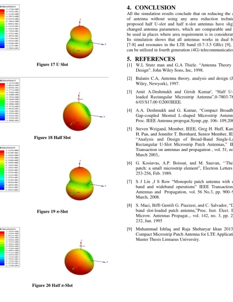
3.3 Gain
By reducing the antenna area we have analyzed that Half
U-slot and half U-slots have comparable gain with U-U-slot and π-slot respectively. Figure (17-20) shows the simulated gains for
Table 4. Gain
Band Freq(GHz) U-
Slot
Half U-Slot
Π- Slot
Half Π-slot
0.75 0.88 1.00 1.13 1.25
Freq [GHz] 0.00
10.00 20.00 30.00 40.00
d
B
(V
S
W
R
t(p
ro
b
e
_
p
in
_
T
1
))
HFSSDesign1
XY Plot 12 ANSOFT
Curve Inf o dB(VSWRt(probe_pin_T1)) Setup1 : Sw eep1
0.75 0.88 1.00 1.13 1.25
Freq [GHz] 0.00
5.00 10.00 15.00 20.00 25.00
dB(V
SW
R
t(p
ro
be
_p
in
_T
1))
HFSSDesign1
XY Plot 6 ANSOFT
Curve Inf o dB(VSWRt(probe_pin_T1)) Setup1 : Sw eep1
0.75 0.88 1.00 1.13 1.25
Freq [GHz] 0.00
12.50 25.00 37.50
dB(V
SW
R
t(p
ro
be
_p
in
_T
1))
pie slot
XY Plot 10 ANSOFT
Curve Inf o dB(VSWRt(probe_pin_T1)) Setup1 : Sw eep1
0.75 0.88 1.00 1.13 1.25
Freq [GHz] 0.00
5.00 10.00 15.00 20.00 25.00 30.00
dB(V
SW
R
t(p
ro
be
_p
in
_T
1))
t slot
XY Plot 10 ANSOFT
[image:4.595.87.515.76.364.2]Figure 17 U Slot
[image:5.595.55.307.67.647.2]
Figure 18 Half Slot
Figure 19 π-Slot
4.
CONCLUSION
All the simulation results conclude that on reducing the area of antenna without using any area reduction technique, proposed half U-slot and half π-slot antennas have slightly changed antenna parameters, which are comparable and can be used in places where area requirement is in consideration. Its simulation shows that all antennas works in dual band [7-8] and resonates in the LTE band (0.7-3.5 GHz) [9], and can be utilized in fourth generation (4G) telecommunication.
5.
REFERENCES
[1] W.L Stutz man and G.A Thiele. “Antenna Theory and
Design”. John Wiley Sons, Inc, 1998.
[2] Balanis C.A, Antenna theory, analysis and design (John
Wiley, Newyork), 1997.
[3] Amit A.Deshmukh and Girish Kumar', “Half U-slot
loadcd Rectangular Microstrip Antenna”,0-7803-7846-6/03/$17.00 ©2003IEEE.
[4] A.A. Deshmukh and G. Kumar, “Compact Broadband
Gap-coupled Shorted L-shaped Microstrip Antennas”, Proc. IEEE Antenna propogat.Symp.,pp. 106- 109,2001
[5] Steven Weigand, Member, IEEE, Greg H. Huff, Kankan
H. Pan, and Jennifer T. Bernhard, Senior Member, IEEE, “Analysis and Design of Broad-Band Single-Layer
Rectangular U-Slot Microstrip Patch Antennas,” IEEE
Transaction on antennas and propagation , vol. 51, no. 3, March 2003,.
[6] G. Kosiavas, A.P. Boissat, and M. Sauvan, ‘‘The
C-patch: a small microstrip element”, Electron Letters pp. 253-256, Feb. 1989.
[7] S J Lin ,J S Row “Monopole patch antenna with dual
band and wideband operations” IEEE Transaction on Antennas and Propagation, vol. 56 No.3, pp. 900–904, March, 2008.
[8] S. Maci, Biffi Gentili G. Piazzesi, and C. Salvador, “Dual
band slot-loaded patch antenna,”Proc. Inst. Elect. Eng. Microw. Antennas Propagat.., vol. 142, no. 3, pp. 225– 232, Jun. 1995
[9] Muhammad Ishfaq and Raja Sheharyar khan 2013 .A
Compact Microstrip Patch Antenna for LTE Applications Master Thesis Linnaeus University.