Frequency Error and Voltage Control by using PI and
Fuzzy Logic Controllers for Multi Area Inter Connected
Power System
T.C. Srinivasa Rao Ravi Ponnala
T.C. Subramanyam
N. Srinivas
Dep.t of EEE, PG Student Dept. of EEE, Dept. of EEE, school of Engg., Dept. of EEE, VCE VCE Shamshabad VCE Shamshabad, NNRESGI, Shamshabad
Hyderabad, India Hyderabad, India Hyderabad, India Hyderabad, India
ABSTRACT
This paper deals with the power system operation, frequency error and voltage control problems. In actual power system operations the load is changing continuously and randomly. As the ability of the generation to trace the change in load is limited due to physical/technical considerations. They result an imbalance between actual and the scheduled generation quantities. This imbalance leads to a frequency error and voltage problems. In general, as the speed of the machine depends on the frequency, any deviation in the frequency may lead to mal-operation of the system. So load frequency control is the key problem in the power system. For specified power rating of the machine the voltage should maintain constant otherwise the system insulation may get damage. In modern power system multi area inter connected systems are used for more reliability and economic purpose. In the multi area inter connected systems the frequency errors and voltage problems can be effectively decreased by using fuzzy logic controller with either of the 3, 5 or 7 membership functions. Here this fuzzy logic controller action also compared with automatic generation control and PI controllers also. By using fuzzy logic controller the frequency error, settling time, peak overshoot, under overshoots are effectively reduced.
Keywords
Frequency error, multi area inter connection, reliability, Automatic Generation Control (AGC), Fuzzy logic controller, membership function, voltage problems.
1.
INTRODUCTION
In power system operation and control the load is varying continuously and randomly. The varying of load may cause change in real and reactive powers. That means the real and reactive power demands are continuously varying and never steady. If active and reactive powers are changes that may are cause change in system frequency and voltages. But for the successful operation of the system the frequency and voltage should be maintain constant at their normal values.
The system frequency and voltage are maintain at their normal values by monitoring the load variations and taking suitable control action, to match the real and reactive power generations with load demand at the losses in the system at that time.
The system frequency is indirectly depends upon the real power demand ,because increasing load on generation unit then more amount of real power is to be supplied. Which is immediately received from the kinetic energy (K.E) power in rotating part, thereby reducing the K.E of angular velocity or speed of the machine.
The frequency at the system is directly depends upon the speed of the machine
f=P.Ns/120. f---system frequency
Ns----synchronous speed
P---number of poles in the machine For the maintain of constant frequency the change in speed is sensed by a speed governing mechanics and control the position at inlet valve to the prime mover there by controlling the stem water supplied to the turbine.
The system voltage is mainly controlled by the reactive power balanced in the system [8]. The excitation of generator must be continuously regulated to match the reactive power demand with reactive power generation otherwise the voltage at various systems may go varying in the large interconnected system.
Figure 1 Block diagram of single area power generating unit.
Power system to meet load demand with more reliability and economical purpose interconnection systems are made. For the successful operation of interconnected electric power system needs the continuous match between the total generation with total load demand plus losses. In actual power system operations the load is changing continuously with respect to time. The imbalance between the generation and the load may leads to frequency error and undesirable effects. This is normally overcome by using controllers or Automatic Generation Controllers (AGC).
Automatic Generation controller’s plays very important role in the power system as its main role is to maintain the system frequency and tie line power flow at their scheduled values. Along with the Automatic Generation Control P, PI controllers also used for control of frequency error [3]. But in these control methods the peak overshoot, peak undershoot and settling times are more. If these factors are more then the system will be damage. To reduce above mentioned factors Fuzzy Logic Controllers are introduced. For the analysis of load frequency error control purpose 10% of step disturbance is created. For this 10% of disturbance the output simulation results are obtained by using PI, Fuzzy logic controllers
2.
INTERCONNECTED POWER
SYSTEMS
Modern day power systems are divided into various areas. For example in India, there are five regional grids, e.g. Eastern Region, Western Region etc. Each of these areas is generally interconnected to its neighbouring areas. The transmission lines that connect an area to its neighbouring area are called tie-lines [1]. Power sharing between two areas occurs through these tie-lines. Two single area power systems are connected through a tie line in order to form an interconnected power system [6]. The main advantage of interconnected power system is to attain the load demand.
The system frequency rises when the load decreases if ∆Pref is kept at zero. Similarly the frequency may drop if the load increases. However it is desirable to maintain the frequency constant such that ∆f=0. The power flow through different tie-lines is scheduled.
Figure 2 interconnected areas in a power system.
3.
FUZZY LOGIC CONTROLLER
Fuzzy logic is another form of artificial intelligence. Fuzzy logic has been recently applied in process control, modeling, estimation, identification, diagnostics, stock market, prediction, agriculture, military science and so on. Fuzzy logic, unlike Boolean or crispy logic, deals with problems that have vagueness, uncertainty, imprecision or qualitative ness [2]. In convention set theory based on Boolean logic, a particular object or variable is either a member (logic 1) of a given set or it is not (logic 0). On the other hand, in fuzzy set theory based on fuzzy logic, a particular object has a degree of membership in a given set which may be anywhere in the range of 0 to 1. The basic property like union (OR), intersection (AND) and complement (NOT) of Boolean logic are also valid for fuzzy logic. In the fuzzy logic system three main stages are there. They are
1). Fuzzification interface 2). Rules base analysis 3). Defuzzification module
For LFC the process operator is assumed to respond to variables error (e) and change of error (ce). The variable error is equal to the real power system frequency deviation (∆f). The frequency deviation ∆f is the difference between the nominal or scheduled power system frequency and the real
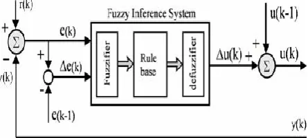
[image:2.595.319.542.632.732.2]A FL based controller consists of three sections namely fuzzifier power system frequency., rule base, and defuzzifier as shown in Fig. 4.15. Two input signals, the main signal and its change for each sampling, to the FL controller are converted to fuzzy numbers first in fuzzifier. Then they are used in the rule table to determine the fuzzy number of the compensated output signal. Finally, the resultant united fuzzy subsets representing the controller output are converted to the crisp values.
[image:2.595.78.257.685.749.2]The FL based controller is designed to act as an integrator controller, such that the resultant incremental output Δu(k) is added to the previous value u(k-1) to yield the current output u(k).
3.1 Fuzzification:
Fuzzification means change of crisp logic to fuzzy logic. In the fuzzy logic the frequency error (e) and change of frequency error (ce) can be split into 5 or 7 or 9 parts. These splitting parts ranges are arranged with the triangular member ship functions (MF).
3.2 Rules Base Analysis:
The output membership grades for different fuzzy sets are derived by Zadeh’s AND and OR rules from the rule table.
The typical knowledge based strategy stores the operation of the process as condition → Action rules of the form For designing the rule base for tuning the integral controller , the following important factors have been taken into accounts This simple rule is applied as follows to determine the sign of Δu.
At region I: e =’ +’ and Δe =’ − ‘. The error is positive and decreasing toward zero. Therefore, Δu is set to positive to reduce the error.
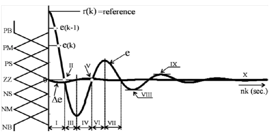
[image:3.595.71.526.257.484.2]At region II: e =’ 0’ and Δe =’ − ‘. The error is zero, but is getting away and increasing in negative direction. Therefore, a negative Δu is assigned to reduce the error.
Figure 4 Operating regions and fuzzy partitioning of the time responses of error e(k) and change of error ∆e (k) for a generalized second order system
At region III: e =’ − ’ and Δe =’ − ‘. The error is negative and increasing. Therefore, Δu is still required to be negative to reduce the error toward zero.
At region IV: e =’ − ’ and Δe =’ + ‘. The error is still negative, but decreasing. Therefore, negative Δu is kept on to reduce the negative error.
At region V: e =’ 0 ’ and Δe =’ + ‘. The error is zero, but increasing in positive direction. Therefore, a positive Δu is applied to increase the controlled output so that the voltage error is reduced.
At region VI: e =’ + ’ and Δe =’ + ‘. The error is positive and increasing. A positive value for Δu will be suitable to reduce the error.
At region VII: A repeat of region I.
At region VIII: e =’ − ’ and Δe =’ 0 ‘. The error is negative and constant since there is no change. Therefore a negative value for Δu should be assigned to decrease the error.
At region IX: e =’ + ’ and Δe =’ 0 ‘. The error is positive and constant. Therefore a positive Δu is required to reduce the error.
At region X: e =’ 0 ’ and Δe =’ 0 ‘. The error is both zero and constant.
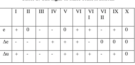
Therefore Δu is set to zero since no change is required for the control signal. The signs of Δu in the regions described above as I to X are listed in Table I, which can be summarized as follows:
Table 1: The signs of basic control actions
Both Fig.4 and Table 1 show that each one of e, Δe, and Δu has three different options for the signs to be assigned. They are either positive or negative if not zero. Keeping in mind these three options, which are represented by three fuzzy sets namely positive (P), negative (N), and zero (Z),
For designing the rule base (table 4.2) for tuning the integral controller the following important factors have been taken into accounts
IF e (k) is Negative Big AND ∆e (k) is Negative Big THEN output is Negative Big
IF e(k) is Negative Big AND ∆e (k) is Negative medium THEN output is Negative Big
Fuzzy logic controller has been used in both the thermal-thermal and hydro-thermal-thermal inter connected areas. Attempt has been made to examine with five number of triangular membership functions (MFs) which provides better dynamic response with the range on input (error in frequency deviation and change in frequency deviation) i.e. universe of discourse is -0.25 to 0.25. The number of rules is 25. The dynamic response are obtained and compared to those obtained with conventional integral controllers [3]. Further, several inputs have been tried out and dynamic responses are examined in order to decide suitable inputs to the fuzzy logic controller (FLC).
3.2.1 Model 1:- 5 MF with 25 Rules
In a fuzzy scale, each membership functions of five linguistic states of triangular type are mapped into the values of Negative Large (NL), Negative Small (NS), Zero Error (ZE), Positive Small (PS) and Positive Large (PL). With the 5MFs 25 rules are formed and are applied to the system. The response curves of Δf1 and Δf2 shows more stability. It shows typical hydro-thermal area like behaviour with fast settling time.
Table 2: Fuzzy Rules for 5 Membership Functions
variable NL NS ZE PS PL
NL NL NL NS NS ZE
NS NL NL NS ZE ZE
ZE NS NS ZE PS PS
PS ZE PS PS PL PL
PL ZE ZE PS PL PL
3.2.2Model 2:- 7 MF with 49 Rules
In a fuzzy scale, each membership functions are divided into seven linguistic stages of triangular type and are given as Negative Large (NL), Negative Medium (NM), Negative
Small (NS), Zero (ZE), Positive Small (PS), Positive Medium (PM) and Positive Large (PL). By using these 7 MF’s 49 governing rules are formed and applied to the system
Table 3: Fuzzy Rules For 7 Membership Function
Variable NL NM NS ZE PS PM PL
NL NL NL NL NL NM NS ZE
NM NL NL NL NM NS ZE PS
NS NL NL NM NS ZE PS PM
ZE NL NM NS ZE PS PM PS
PS NM NS ZE PS PM PL PL
PM NS ZE PS PM PL PL PL
PL ZE PS PM PL PL PL PL
3.3 Defuzzification:
The center of gravity (COG) defuzzification method is used to compute the output control (u) as following
U=Nu(∑imWiYi)/ (∑imYi)
Where wi is the grade of ith output MF, yi is the output label for the value contributed by the ith MF, and m is the number of contributions from the rules.
4.
FREQUENCY ERROR CONTROL OF
SINGLE AREA SYSTEM
4.1
Frequency Error Control Of Single
Area System Using AGC
[image:4.595.317.547.580.768.2]Whenever there is an increase in load on generating unit more amount of real power is to be supplied, which is immediately received from the kinetic energy (K.E) power in rotating part there by reducing K.E of angular velocity or speed of the machine. There will be a change in speed which is measure of real power in balance. The change in speed sensed by a speed governing mechanism and control the position of inlet valve to the prime mover, there by controlling the stem water supplied to turbine and hence frequency [7]. This action is a slow process since mechanical elements are involved and usually it takes more time.
Figure 5 Simulation diagram of single area frequency error control by using speed governing system
G1 => Governor=>
,
T1 => Turbine =>,
GL => Generator Load =>
,
N => Speed Drop =>
I II III IV V VI VI I
VI II
IX X
e + 0 - - 0 + + - + 0
∆e - - - + + + - 0 0 0
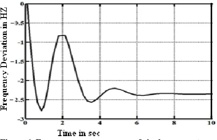
Figure 6 Frequency error response of single area system
4.2
Single Area Frequency Error Control
Using PI Controller
[image:5.595.317.543.112.225.2]The integral controller is used to control the frequency error. The PI controller improves the steady state performance and also it reduces steady state frequency error. The simulation diagram is shown in Fig.7.
Figure 7 Simulation diagram of single area frequency error control by using PI controller.
K1 => Gain =>
-
0.8,
GL -> Generator Load =>
,
I1=> Integrator =>
G1 => Governer =>
,
T1 =>Turbine =>
,
K2 => 0.425Figure 8 Frequency error response of single area system with PI controller
4.3
Single Area Frequency Error Control
Using Fuzzy Logic Controller:
Fuzzy logic controller is advanced controller to reduce the frequency error. For reducing of frequency error purpose the in frequency is split into 5 or 7 parts. For each part one
membership function (triangular) is assigned. The simulation diagram is shown in Fig. 9
Figure 9 Simulation diagram of single area frequency error control by using FUZZY logic controller
ZOH => Zero Order Hold, FLC => Fuzzy Logic Controller, UD => Unit Delay =>
,
K =>
,
G1 => Governor=>
T1 => Turbine =>
,
GL -> GeneratorLoad =>
.
The settling time is reduced to 4 sec. And peak overshoot, peak undershoots are also considerably reduced. The frequency error, steady state responses is shown in Fig.10
Figure 10 Frequency error response of single area system with Fuzzy logic controller
[image:5.595.55.278.323.654.2]By using of fuzzy logic controller the dynamic and steady state responses is considerably improved [5] as compared with the conventional controller and PI controller. The performance characteristic values are compared in table 4.
Table 4: Performance comparison of speed governor, PI and Fuzzy controllers
Specification/Controller Peak overshoot
Peak undershoot
Settling time Speed governor
controller -- 2.9 8
PI Controller 0.4 2.9 7
[image:5.595.319.538.382.522.2]5.
FREQUENCY ERROR CONTROL OF
TWO AREA (thermal-thermal)
SYSTEM
5.1
Two Area Frequency Control Using PI
Controller
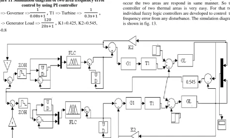
[image:6.595.318.539.117.263.2]In inter connected power system the frequency error of each area is controlled by different PI controllers. The two areas are interconnected through “Tie line”. At balanced condition the Tie line power is equal to zero. Two area interconnected power system frequency error control using PI controller simulation diagram is shown in Fig.11.
Figure 11 Simulation diagram of two area frequency error control by using PI controller
G1 => Governor =>
T1 => Turbine =>
,
GL -> Generator Load =>
,
K1=0.425, K2=0.545,K3-0.8
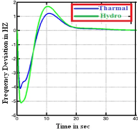
The two areas are said to same(thermal-thermal). So the out put response is same for both areas with same PI controllers. The frequency error response is shown in fig. 12.
Figure 12 Frequency error response of two area system with PI controller
5.2
Two Area Frequency Error Control
Using Fuzzy Logic Controller
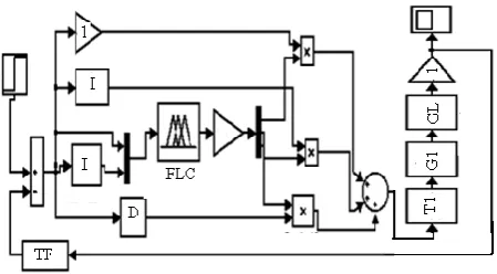
Here two areas are said to thermal. So generally the characteristics of two areas is same. Means if any disturbance occur the two areas are respond in same manner. So the controller of two thermal areas is very easy. For that two individual fuzzy logic controllers are developed to control the frequency error from any disturbance. The simulation diagram is shown in fig. 13.
Figure 13 Simulation diagram of two area frequency error control by using Fuzzy logic controller
Table 5: Performance comparison of PI and Fuzzy controllers
By using Fuzzy logic controller the peak overshoot, peak undershoot, settling times are considerably i.e about 45-50% than PI controllers. The response is shown in the fig.14. Specification/Controller Peak
overshoot Peak undershoot
Settling time
PI Controller 0.4 2.7 7
[image:6.595.66.533.339.619.2]Figure 14 Frequency error response of two area system with fuzzy logic controller
6.
FREQUENCY ERROR CONTROL OF
TWO AREA (THERMAL-HYDRO)
SYSTEM
6.1
Two Area (Thermal-Hydro) System
Using PI Controller
The integral controller is used to controller is improves the steady state error in the interconnected two-area hydro-thermal [9] system. These two areas have different characteristics. If any disturbance occur the two areas are respond in different even though same controllers are provided for same areas. The simulation diagram for two area system with PI controller is shown in Fig. 15.
Figure 15 simulation diagram of two (Hydro-Thermal) area frequency error control by using PI controller
HT => Hydraulic Turbine =>
,
HA => HydraulicAmplifier
=>
[image:7.595.315.541.232.445.2]
Generally thermal plant generators have less moment of inertia so the control action is fast than hydro plant systems. The responses of two area system with PI controller is shown in Fig.16.
Figure 16 Frequency error response of two (Hydro-Thermal) area system with PI controller
6.2
Two Area (Thermal-Hydro) System
Using Fuzzy Logic Controller
[image:7.595.55.294.376.568.2]Figure 17 simulation diagram of two (Hydro-Thermal) area frequency error control by using Fuzzy logic controller
[image:8.595.55.280.389.508.2]Hydro turbines have high moment of inertia than thermal turbines. So generally the change in speed response is very slowly. Due to that the control action is slowly respond in hydro turbines than thermal turbines. The response of two area(thermal-hydro) system with fuzzy logic controller is shown in Fig. 18.
Figure 18 Frequency error response of two(Hydro-Thermal) area system with Fuzzy logic controller
Table 6: Performance comparison of PI and Fuzzy controllers for two area (thermal-hydro)system
7.
VOLTAGE CONTROL
7.1
Voltage Control By Using Fuzzy Logic
Controller
The main objective of the automatic voltage regulator is to control the terminal voltage by adjusting the generators exciter voltage. It must keep track of the generator terminal voltage all time and under any load condition, working in order to keep the voltage within pre-established limits. Based on this it can be said that AVR also controls the reactive power generated and the power factor of the machine once these variables are related to the generator excitation level. The simulation diagram designed for single area (Thermal) frequency control by using PI control. In this paper for designing of single area KP=120 Hz/p.u.MW, KH=1 Hz/p.u.MW, KT=1 Hz/p.u.MW, Tp=20 Sec, TH=0.08Sec. TT=0.3Sec. B=0.425 p.u.MW/Hz, R=2.4 p.u.MW/Hz.
Figure 19 simulation diagram of single area voltage control by using Fuzzy logic controller
Fuzzy logic controller is used to tune the integral gain , K of AVR in a single area power system. The critical value of K of conventional PI controller is considered as the base value in the design of the proposed fuzzy logic control scheme. In AVR system fuzzy with PI control scheme has been implemented [10].
Specification/ Controller
Peak overshoot
Peak
undershoot Settling time
PI Controller
h
y
d
ro
th
erm
al
h
y
d
ro
th
erm
al
h
y
d
ro
th
erm
al
1.8 1.2 5.1 4 21 21
Fuzzy Logic
[image:8.595.318.543.513.637.2] [image:8.595.48.290.576.690.2]23
8.
CONCLUSION
Fuzzy logic controller gives a very good control action of frequency error, less peak undershoot, less peak overshoot and less settling time as compared with the conventional and PI controllers. The simulation results for single area (thermal), multi area (thermal - thermal and thermal-hydro) power system with conventional P, PI controllers and fuzzy logic controllers is obtained.
By controlling the excitation input to the generator by using fuzzy logic controller the voltage maintain constant at their normal values. By using fuzzy logic controller the output voltage is very fast and accurately controlled than the PI controllers.
Hence by using FUZZY logic controller the frequency error and voltage problems are effectively and quickly reduced. So the power system operation and control is very easy and successfully operated without any damage to the electrical equipment.
9.
REFERENCE
[1] P.V.R. Prasad and Dr.M. Sai Veeraj. “Fuzzy Logic Controller Based Analysis Of Load Frequency Control Of Two Area Inter Connected Power System,” International Journal of Emerging Technology and Advanced Engineering
[2] G.A.Chown and R.C.Hartman, “Design and Experience with a fuzzy logic controller for automatic generation control” IEEE Trans. On Power Systems, Vol.13, No.3, pp. 965-970, August 1998.
[3] G. Chen, “Conventional and fuzzy PID controllers: an overview”, International Journal of Intelligent and Control Systems, 1, 1996, pp. 235±246.
[4] Janardan Nanda, Ashish Mangla and Sanjay Suri, “Some new findings on automatic generation control of an interconnected hydrothermal system with conventional controllers,” IEEE Transactions on Energy Conversion, vol.21, No. 1, pp. 1 87-193, March 2006.
[5] IEEE Committee report, “Dynamic models for steam and hydro turbines in power system studies,” IEEE Trans. on Power Apparatus and Systems, Vol. 92, No. 4, pp. 1904-1911, 1973.
[6] C. Concordia and L. K. Kirchmayer, ―Tie – line power and frequency con-trol of electric power system: Part II‖ AISE Trans, III-A, Vol. 73. pp. 133 – 146, Apr. 1954.
[7] K.C.Divya and P.S.Nagendra Rao, “A simulation model for AGC studies of hydro-hydro systems,” Electrical Power and Energy Systems, vol. 27, pp. 335-342, 2005. [8] Paraveen Dabur, Naresh Kumar Yadav, Ram Avtar,
“Matlab design and simulation of AGC and AVR for single area power system with fuzzy logic control”, “International Journal of Soft Computing and Engineering”.
[9] J.Nanda and A.Mangla, “Automatic generation control of an Interconnected hydro-thermal system using conventional Integral and fuzzy logic controller,” 2004 IEEE International Conference on Electric Utility Deregulation, Restructuring and Power Technologies, Hongkong, pp. 372-377, April 2004.
[10] Loukianov A. G., Sanchez E., Lizarde C. 2007. Force Tracking Neural Block Control for an Electro-Hydraulic Actuator via Second-Order Sliding Mode. Int. Journal of Robust and Nonlinear Control, Wiley InterScience, 20, June : 319-332.