Implementing Autonomous Navigation Robot for
building 2D Map of Indoor Environment
Wael R. Abdulmajeed,
Ph. D Mechatronics Engineering Department / Al– Khwarizmi Engineering College / University ofBaghdad
Revan Zuhair Mansoor
Mechatronics Engineering Department / Al– Khwarizmi Engineering College / University of
Baghdad
ABSTRACT
This paper solves the problems of Simultaneous localization and mapping (SLAM) that deals with local path planning of an autonomous mobile robot in indoor environment, by using sonar sensors for object detection and range information, and also uses wheel encoders for tracking robot position and orientation based on dead-reckoning process.
In this work, mobile robot uses wall-follower technique for an autonomous navigation in unknown indoor environment. This is based on the behavior of the mobile robot developed for fully automatic navigating beside the wall without shocking it and also avoids hitting any obstacles during navigation near the wall. This work involves the construction of control algorithm, which has four functions: follow the wall, obstacles avoidance, determine the location of mobile robot simultaneously with building 2D map within an unknown environment.
Two cases were described in this project, the result of first case showed how mobile robot can navigated successfully without supervisor in two mini room and corridors and showed how the robot with sonar can drew this area during navigation, the result of second case showed how mobile robot could navigate successfully without supervisor in room with three obstacles and showed how mobile robot with sonars could drew these obstacles with walls of plan during navigation. Both cases used wall following techniques for navigation to follow the walls and avoided all obstacles that are located on its way.
Keywords
mobile robots, sonar, SLAM, mapping, localization, navigation
1. INTRODUCTION
Robots are made to go and do what humans either cannot, or do not want to do. SLAM describes the process of building a map of an unknown environment and computing at the same time the robot position with the constructed map. Both steps depend on each other. A good map is necessary to compute the robot position and on the other hand just an accurate position estimate yields to a correct map [1].
Because navigation, localization, path planning and mapping are an essential step in a mobile robot, many of the approaches used is simple heuristics successively searching for face connected cells or configuration with or without the minimization of a criterion.
Some Literatures like Literature of Howie Choset presents a method for simultaneous localization and mapping that exploits the topology of the robot’s free space to localize the robot on a partially constructed map, the robot achieves SLAM by constructing a graph and comparing the “recently” constructed graph to subgraphs of the already constructed map [4].
And others Literatures solve problem of SLAM by using genetic algorithm like Literature of Tom Duckett in which a population of candidate solutions is progressively refined in
order to find a globally optimal solution. A genetic algorithm was developed to solve this problem, producing a global solution by searching the space of possible robot maps [5],
Other paper like Young-Ho Choi describes a geometrically constrained Extended Kalman Filter (EKF) framework for a line feature based SLAM, which is applicable to a rectangular indoor environment [6],
Paper of Jun Okamoto Jr. introduces a method of landmark selection and clustering for on-line SLAM in omnidirectional images that does not require any prior knowledge of the environment, and thus can be in theory used equally in any situation [7],
Paper of Ngai Ming Kwok used Gaussian sum filter (GSF) that will be applied in solving the SLAM problem for a mobile robot using bearing-only measurements. Gaussian parameters are designed on the basis of minimizing the representation error [8],
One of the main objectives of mobile robotics is capable of moving in real environments without the help of a human operator by used different techniques.
Pioneer 3 DX is a mobile robot that is used in our work which has sonar sensors. the programs that used for this robot are the Advanced Robotics Interface for Applications (ARIA) that program with C++ package ( Visual C++.Net ), and ARNetworking software was used for setup Wireless TCP/IP Ethernet-to-Serial connection between robot and PC.The data from sonar sensors is the distance between the sonar and object. Pioneer robot contain wibox which is represent An Ethernet serial bridge converts an RS-232 serial connection to a TCP/IP connection available through an 802.11 (Wi-Fi) wireless network, It is mounted on a robot, and connected to the robot microcontroller's serial port and configured to join a certain wireless network as a client station and given an IP address. Software may then connect to a TCP port at that address and send and receive data to/from the robot over the serial port connection.
2. Navigation and Obstacles Avoidance
Wall following theory for mobile robot is a technique makes mobile the robot navigate beside the wall without shocking it and also avoid hitting any obstacles during navigation near the wall. Wall following is useful for SLAM projects of indoor environment because mobile robot can move in most area of the plan without supervisor by using Wall following technique.2.1 Robot Vision Range
The way to make robot follow the wall and avoid hitting any obstacles is done by using the reading of sonars to search the right walls to following it. Pioneer 3-dx has eight sonars shown in Figure (1); each sensor can detect obstacles in range from ten centimeters to five meters.
Fig 1: The Sonar Arrangement for p3dx.
In this project, all eight sonars are divided into three groups:
[image:2.595.314.509.156.212.2]Left side represents: (sonar0 + sonar1 + sonar2) Front side represents: (sonar3 + sonar4) Right side represents: (sonar5 + sonar6 + sonar7)
Fig 2: robot vision of mobile robot.
And also divide the viewing angle range of the sonars into three groups :( Near, good, far)
Fig 3: sonars range reading.
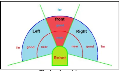
And by combining robot vision (left, front, right) and sonars range reading (near, good, far) we get 27 situations. Figure (4) shows the Distribution of these groups on the robot
Fig 4: robot vision range.
2.2 Use Robot Vision Range for Follow Right
Wall and Avoid Obstacles
Each robot vision has three ranges and by combining robot vision and sonars range reading as shown in Table (1), we get 27 situations.
Table (1) robot vision combines with sonar reading.
In this work choosing suitable value of rotation and transition velocity of mobile robot as a reactive of any one of 27 situations, will make the robot follow the wall and avoid any obstacle without Intervention of supervisor.
Imagine a robot with a distance sensor on its right side and two motors. The robot can move forward by positive transition speed and go backward by negative transition speed; it can turn left by positive rotation speed. It can turn right by negative rotation speed. Now suppose the robot must follow a wall to its right. Here are some solutions to make the robot follow a wall:
a- measure distance to wall. b- If the wall is too close, move away from wall. c- If the right wall is acceptably close, go toward the wall, and
back to step (b).
[image:2.595.65.246.267.412.2]d- If the right wall is too far away, keep searching for a wall by going forward and turning right at same time, and back to step (b).
Fig 5: Navigation in open space until finding a wall.
In each 27 situations, the mobile robot react, a suitable movement for following the right wall by making the right side of mobile robot to be at good range to follow the right wall and not allowing all sides of robot be at near range to avoid crashing any walls and obstacles at all time of navigation. Change the reaction of any one of these 27 situations will affect the behaviors of work, like not following the wall or crashing it.
3. LOCALIZATION AND MAPPING
Two different approaches to the mobile robot localization problem exist: relative and absolute. The first one is based on the data provided by sensors measuring the dynamics of variables internal to the vehicle like encoder that we are used it to determine the position and orientation of our robot in the plan; absolute localization requires sensors measuring some parameters of the environment in which the robot is operating. If the environment is only partially known, the construction of appropriate ambient maps is also required.
Robot vision
situations of Sonar range reading during navigation
[image:2.595.325.524.429.549.2] [image:2.595.58.251.465.597.2] [image:2.595.58.252.642.758.2]SLAM in the mobile robotics community generally refers to the process of creating geometrically consistent maps of the environment. Topological maps are a method of environment representation which captures the connectivity (i.e., topology) of the environment rather than creating a geometrically accurate map.
The pioneer 3-dx robot is support with eight sonars that provide object detection and range information for collision avoidance. In our work we use sonars of pioneer robot to building a map for indoor environment.
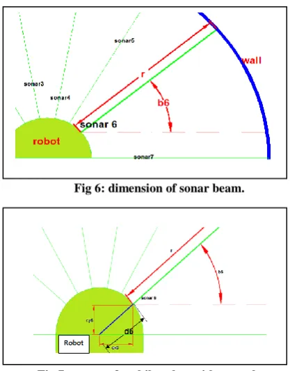
[image:3.595.55.264.186.453.2]Fig 6: dimension of sonar beam.
Fig 7: center of mobile robot with sonar beam
r is distance between robot and wall
b6 is angle between range line of sonar 6 and x axis
Cx6 is the x distance between sonar6 and center of robot
Cy6 is the y distance between sonar6 and center of robot
d6 is the distance between sonar6 and center of robot
By using last factors of all sonars of pioneer 3-dx with it position and orientation of in real time we can get equations of mapping.
For n=0 to n=7
Xsn(t) = X (t) + (rsn(t) +dn) × cos(bn+ φ (t))
Ysn(t) = Y (t) + (rsn(t) +dn) × sin(bn+ φ (t))
n: represent real number from 0 to 7
t: represent time
X (t) and Y (t) and φ (t): represent the position and orientation of mobile robot in the plan in time t
rsn: represent the distance from any obstacles and walls that
robot is detected by using sonars to the robot position.
bn: represent the orientation of sonars robot. dn: Distance between sonars and center of robot.
Xsn(t) and Ysn(t): represent the position of obstacles and walls
in the plan that robot is detected by using sonars in time t.
In this project the distance of center of mobile robot (dn) of all sonars beam changed to be 130 mm and this number is approximately to true value of all distance range of sonars place to the center of robot.
3.1 Choosing suitable filter for mapping by
using sonar
[image:3.595.316.536.289.430.2]Mapping by sonar using the last equations has some troubles in practical results because of the relatively wide angle of the sonar beam; an isolated sonar reading imposes only a loose constraint on the position of the detected object, This problem will make wide sonar beam cause a poor directional resolution and make the true position of the object detected not known along the fan-shaped area shown in figure (8); the blue area are all the range that sonar can read seeing obstacles a1, a2 and a3. They are in different places from the sonar but the sonar reads them at the same position. R1 is distance from a2 to sonar.
Fig 8: sonar viewing angle.
Sonar viewing angle of pioneer robot is approximately 30 degree and by using triangles equations we can get these functions:
R1 R2 =
L1
L2 and also R1 R3 =
L1 L3 …..
In our sonor of robot R1=5meters and L1=1.3388meters and if R2=2.5meters then L2=0.67m.
By reducing the range distance from 5 m to 2.5 m the error reduced to be
e=L1-L2=1.3388-o.67= 0.6688m
In our work for mapping we use filter for just reading the desired range that we want for drawing walls and obstacle of environment.
4. STRUCTURE OF CONTROLLER
environment and also path plan of mobile robot in that environment. The robot vision gets data from (sonar Sys.) and uses it for following the wall by sending the command from translation and rotation velocity command to the (speed Sys.) of left and right motor. For build mapping first, data of (sonar Sys.) that are entered the filter for removing any range value that is more than the desired value of filter, the output of flitter are merge with data of (Position Sys.) in the equations of mapping and save the result in text document. To build path plan for mobile robot, data of position and orientation of robot are getting from position Sys and save it in text document.
Fig 9: Structure of controller to implement SLAM for mobile robot
5. PROGRAMS AND FACTORS THAT
ARE USED IN WORKS
This project used (c++.net) to build a program for navigation and mapping. Navigation built by using some command in (c++.net) for initialized the robot and controlled the motors of the robot to navigate it in the plan.
mapping built by using mathematical equations as a command in (c++.net), these equations extracted two text document of data results, one for mapping of the plan and other for path planning of mobile robot, we used the data of these two text document in Microsoft excel to plot the results of mapping and path planning data both of them in one figure to show the final result.
There are some variables and factors found in c++.net and these variables affect the navigation of the robot and also the
mapping result. The variables and factors for the main program are:
a- there are two group one for robot vision (near, good, far) and other group for range (left side, front side, far side) the resulted in of merging them is robot vision range. The robot vision ranges that are used in main program are:
1-near range of robot is less than 500mm. 2- Good range of robot is more than 500mm and less than 700
mm.
3- Far range all value that is more than 700 mm.
b- Value of translation and rotation velocity in main program that mobile robot is used it for navigation in the plan:
forward. 3- Set translational velocity to ((-100 mm/sec) for backward motion. 4- Set rotational velocity to (-40 degrees/sec) for fast clockwise rotation. 5- Set rotational velocity to (-10 degrees/sec) for slow clockwise rotation. 6- Set rotational velocity to (40 degrees/sec) for fast counter
clockwise rotation. 7- Set rotational velocity to (20 degrees/sec) for slow counter
clockwise rotation.
c-the variables that affect mapping directly are:
1- Main program is used all eight sonars of pioneer 3-dx robot. 2- The suitable filter for main program is 1500 mm.
Those values are for the main program and any change on any value makes the result of mapping or path plan change.
6. EXPERIMENTAL RESULTS
These Practical experiments are shown navigation and mapping of cases studies of this work. Mobile robot navigates by changing the translation and rotation speed of mobile robot and use sonar to detect walls and objects for navigation and 2d mapping
6.1 case 1
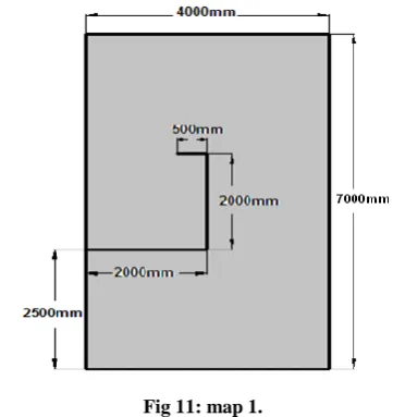
[image:5.595.332.513.89.281.2]In the first case mobile robot navigates in two mini rooms and corridors shown in figure (10) and figure (11) without supervisor by control the rotation and translation velocity for following the right wall and avoids any obstacles in the environment.
[image:5.595.53.290.414.513.2]Fig 10: made-up environment build by using boxes of wood and sheets of cartoons
Fig 11: map 1.
The aim of this case is show how mobile robot could navigate in two mini room and corridors and show how the robot with sonar can mapping this area during navigation. We use main program in this case. The mapping result is shown in figure (12) Mobile robot travel from point A (0, 0) and back to this point (-32, -300) and the time Consumed is 173 second and total distance of navigation is 26386mm and number of points of mapping result at this case is 5013 points. The mapping result of this case was not clear but it approximately showed the dimension of the plan and the path the robot chose to move in this plane.
[image:5.595.154.447.579.744.2]6.2 case 2
[image:6.595.68.273.179.296.2]In case two, mobile robot navigated in room with dimension (7 x 4) meters have two obstacles in dimensions (0.75 x 0.35) meters and one obstacles in dimensions (0.5 x 0.35) shown in figure (13) and figure (14), mobile robot navigate without supervisor by control the rotation and translation velocity for following the right wall and avoiding any obstacles in the environment.
Fig 13: made-up environment build by using boxes of wood and sheets of cartoon
[image:6.595.311.544.227.356.2]The aim of this case was to show how mobile robot can navigate in room with three obstacles and show how mobile robot with sonars can drew these obstacles with walls of plan during navigation.
Fig 14: map 2
6.2.1 Case 2.1
[image:6.595.59.233.379.539.2]This case is used same factor of main program. In this case shown in figure (15) Mobile robot traveled from point A (0, 0) and back to this point (1152, -73) and the time Consumed is 223 second and total distance of navigation is 28410mm and number of points of mapping result at this case is 4344 points.
Fig 15: mapping result of environment and path plan of mobile robot of case 2.1.
2.2 Case 2.2
The changing on the main program was changed the robot vision range that affect the navigation of mobile robot. Changing on the robot vision of main program are (near less 300mm) and (good between 300mm and 400mm) and (far is more than 400mm). In this case shown in figure (16) mobile robot travel from point A (0, 0) to point B (18, 2778) and the time Consumed is 135 second and total distance of navigation is 17400mm and number of points of mapping result at this case is 3239 points. In this case mobile robot travel near to the wall more than other case because the robot vision near range choose to be 300 mm that make minimum distance between robot and wall 300 mm.
Fig 16: mapping result of environment and path plan of mobile robot of case 2.2.
7. CONCLUSIONS
The following points summarize the main conclusions of navigation and mapping with path plan result derived from Experiments of work:
1-Wall following technique make mobile robot move without supervisor and also make mobile robot navigate in unknown environment without need the map of plan.
2-Increasing speed to high value makes mobile robot in danger of crashing and affects the stability of path plan, and also decreasing the speed to low value makes the time consumed in high value.
3-Decreasing the value of robot vision range of mobile robot especially near range makes mobile robot move close to the wall and that make it in danger of crashing. Increase the value of robot vision of mobile robot especially near range make mobile robot not able to move in narrow corridor.
4-The effect of varying sensor range or robot vision showed that it does not only effect on the distance between the mobile robot, obstacles and walls, but also it affects the shape of the path from start to end point. Increasing the sensor range may force the robot to take an entirely different path to the goal especially if it has to go through small openings with respect to the sensor range
5-Wall following is useful for SLAM projects because mobile robot can move in most aria of the plan by using Wall following technique that will make robot detect most walls and obstacles in the plan by using sonar sensors to mapping it during navigation.
[image:6.595.56.288.610.743.2]mapping using low speed better than mapping using main speed but also decreasing speed makes the time consumed of high value
7-Increasing value of desired filters affected on the mapping result and made it not clear and useless to detect the dimension of plan, and also decreasing the value of the desire filters made map result clear and good and better than mapping using main program but decreasing the desired filters to low value made no mapping result or discrete little point in the plan
8-Using one sonar for mapping made mapping result clear but also using all sonar of mobile robot made robot detects all obstacles and walls that it is cannot detect by using one sonar.
9-Mapping use sonar did not show the details of the plan of spatial obstacles and tiny object.
8. REFERENCES
[1] Elmar A. R uckert, ''Simultaneous localization and mapping for mobile robots with recent sensor technologies'', Graz University of Technology Institute for Computer Graphics and Vision, Master Thesis December 2009.
[2] Ahmed Rahman,''A Fuzzy Logic Control for Autonomous Mobile Robot '', University of Baghdad, Al-Khawarizmi College for Engineer, Mechatronics Department, Msc thesis, 2009.
[3] 'Pioneer 3 mobile robot operation manual', 2007.
[4] Howie Choset, Keiji Nagatani, '' Topological Simultaneous Localization and Mapping (SLAM) '', IEEE Transactions on robotics and automation, 2-APRIL- 2001.
[5] Tom Duckett, '' A Genetic Algorithm for Simultaneous Localization and Mapping'', IEEE International Conference on Robotics & Automation, September- (14-19)-2003.
[6] Young-Ho Choi ,Tae-Kyeong Lee ,Se-Young Oh, '' A line feature based SLAM with low grade rangee sensors using geometric constraints and active exploration for mobile robot'', Journal Autonomous Robots, 1-January-2008.
[7] Jun Okamoto Jr., Vitor Campanholo Guizilini, '' On-line SLAM Using Clustered Landmarks with Omnidirectional Vision'', Journal of the Brazilian Society of Mechanical Sciences and Engineering, Dec-2010,