MODELLING AND EVALUATING
FLUID SOFTWARE ARCHITECTURES FOR INTELLIGENT ENVIRONMENTS
Gerd Kortuem
Lancaster University, Computing Department, UK
Abstract: In this paper we introduce a model for specifying fluid architectures of intelligent environments. A fluid architecture is one that is able to accommodate continuous structural changes without aversely affecting the system’s behaviour. The model enables designers to specify structural modifications that may be performed by users as part of the normal interaction and which must be supported by the underlying environment infrastructure. The model is formulated as a generative architectural style: it defines component types, connector types and rules for their composition. This leads to a model that can describe an unlimited number of concrete architectures. To demonstrate the utility of our model, we discuss the design, architecture and change scenarios of an ambient display system.
Keywords: Ubiquitous computing, intelligent environment, software architecture, adaptation, structural changes, architecture evaluation.
1. INTRODUCTION
Ubiquitous computing envisions a computing infrastructure that seamlessly aids users in accomplishing their tasks and renders the actual computing devices and technology virtually invisible [Weiser (1)] and distraction-free [Garlan et al (2)]. One approach to realize this vision is to turn everyday objects and architectural spaces into interfaces to an otherwise invisible computational system. This idea has led to the development of intelligent environments, a new and important category of interactive systems whose realization is tightly integrated with the physical world. Intelligent environments mediate between the physical and the digital world: they promise to facilitate interaction with information away from the desktop and as part of everyday activities, they make use of non-traditional interface technologies (e.g. sensors, embedded computing devices); and they require new interaction models based on implicit or physical interaction (e.g. tangible interfaces [Ishii and Ullmer (3), embodied interaction [Dourish (4)].
One aspect of intelligent environments that has received scant attention in the past is their ability to afford change. As emphasized by Rodden and Benford (5), living and work environments are subject to continuous transformation: they are modified by the people who inhabit them in a variety of ways, for a variety of purposes and with different frequencies. Some of these changes are performed by the inhabitants themselves (for
example, moving furniture in the house) while other are performed by professionals (for example, rewiring of an old building). Intelligent environments are composed of the physical objects and artefacts that surround us and the buildings we inhabit. As such, they are subject to the same dynamics as the rest of our living and work environments.
In this paper, we investigate architectural models for intelligent environments. The key goal of our work is the ability to model user-induced structural changes of intelligent environments, leading us to the notion of fluid software architectures. Our approach is inspired by research in dynamic software architectures [Allen et al (6), van der Hoek (7)] and reconfigurable distributed system [Kramer and Magee (8). We describe an architectural model for intelligent environments that allows designers to incorporate change aspects into the architectural design. We do this by supporting architectural change scenarios based on physical reconfiguration.
2. CASE STUDY: AMBIENT WEB MONITOR
To make our discussion more concrete we use the Ambient Web Monitor, a system that was designed and implemented by a group at University of Karlsruhe [Gellersen and Schmidt (9)], as case study. The Ambient Web Monitor is a collection of digitally augmented posters that provide users with peripheral awareness of the popularity of specific web sites. Each poster is a large scale print of a web page illuminated by a spot light (Fig. 1). The intensity of the spot light shinning on each poster corresponds to the amount of traffic directed at the web page (measured in page hits per time interval): the poster of a web page that receives many page hits is brightly illuminated while a web page with no traffic is not illuminated. As traffic of a web page increases or decreases, so does the light intensity. As a result, the system provides a sense not only of how much interest a particular project raises on the web, but also of how this interest is distributed across different projects.
A key issue in the design of the Ambient Web Monitor is that it should afford similar physical manipulations as other artefacts in a typical office environment. Chairs for example can easily be moved from one room to the next without loosing their usefulness. Similarly, it is easy to buy a chair and add it to an existing table. To identify user manipulation that should be supported by the web monitor we collected typical change scenarios (Table 1). Change scenarios can broadly be classified into three categories: 1. changes that concern a system as a whole, 2. changes that only concern individual system components, and 3. changes that concern two or more system. The change scenarios represent requirements for the Ambient Web Monitor system. Users should be able to perform the activities described in these scenarios without having to reprogram or rewire the system. For the purpose of this paper, we focus on changes which are clearly part of the normal usage pattern and ignore changes that substantially alter the system’s functionality. Thus, for example, we excluded from consideration changes to the system that are the result of modified functional requirements.
[image:2.595.111.485.33.175.2]Figure 1. Ambient Web Monitor. (From Gellersen and Schmidt (9))
TABLE 1. Change scenarios for the Ambient Web Monitor
Change scenario Example Scope
1. Setup system for the first time
Starting to use the Ambient Web Monitor after purchase or development. Involves setup and installation in office
Entire system
2. Move system to new location
Moving Ambient Web Monitor from office
into hallway Entire system
3. Remove system from location
Ceasing to use the Ambient Web Monitor (temporarily or permanently). Involves complete breakdown.
Entire system
4. Move poster to new
location Moving a poster from office into hallway
Individual component
5. Remove poster from system
Removing a poster from Ambient Web Monitor
Individual component
6. Add new poster to system
Adding a new poster to the Ambient Web Monitor. The purpose is to monitor web traffic to a new URL.
Individual component
7. Replace poster with another one
Removing a poster and replacing it with a different one. The purpose is to change a monitored URL.
Individual component
8. Combining two existing systems
Moving two Ambient Web Systems, which
In order to investigate system architectures that support the identified change scenarios we have reimplemented the Ambient Web Monitor. Our original and naïve implementation employed a centralized architecture in which the lights were controlled by a single process on the web server. It was easy to implement, but adding or removing a poster required software modifications in addition to manipulations of the lights. Setting up the system and tearing it down requires careful disassembly of the light fixtures. More importantly changing a URL (for the purpose of changing the web page the system monitors) requires access to a computer terminal and reconfiguration of the server process. Thus, adding, removing or changing a poster is not simply a matter of physically adding or removing it, and is not a task that can be performed by the end user. Instead, it requires the intervention of a programmer.
The inability to accommodate the required structural modifications is due to an inappropriate system architecture which is too rigid and inflexible. Thus, we need to turn our attention to architectural models for intelligent environments.
3. CAPTURING CHANGE REQUIREMENTS WITH FLUID SOFTWARE ARCHITECTURES
While there has been a much work on enabling technologies and software tools for intelligent environments, the problem of how to specify and model such systems on an abstract level has received only scant attention. Yet, high-level system models that specify essential system properties and abstract from implementation specific details are vital for a rigid and effective engineering process. The lack of tailored specification methods for intelligent environments is a fundamental shortcoming, especially in the context of business critical applications and for systems that consists of large numbers of networked components.
For a number of years, software architecture approaches have been used for modelling and analyzing complex software systems [Perry and Wolf (10), Garlan and Shaw (11). A good architecture can help ensure that a system will satisfy key requirements in areas such as performance, reliability, portability, scalability, and interoperability. Despite the importance of architectural models there has been surprisingly little research on architectural models for pervasive systems (see Chemg et al (12) for an exception). Most ubiquitous computing systems described in the literature have been developed without formal specification.
Intelligent environments pose a particular challenge for the field of software architecture because of their
inherent dynamics. As emphasized by Rodden and Benford (5), living and work environments are subject to continuous transformation: they are modified by the people who inhabit them in a variety of ways, for a variety of purposes and with different frequencies. Intelligent environments are composed of the physical objects and artefacts that surround us, and the buildings we inhabit. As such, they are subject to the same dynamics as the rest of our living and work environments. Important is that these changes are part of the normal and expected usage pattern – they are not extraordinary circumstances that only happen occasionally. Thus we can formulate a fundamental requirement for intelligent environments:
Intelligent environments must be change resilient with respect to structural modifications imposed by users.
Change resilience is a non-functional requirement that is related to usability, reliability, dependability, availability, and maintainability. Resilience is the ability to assimilate change without dysfunction: a resilient system will maintain its ability to function without requiring extensive maintenance.
If the observation is correct that evolutionary structural changes are an inevitable part of intelligent environment, does it still make sense to speak about its architecture as a static, immutable concept? To answer this question, we must clarify what we mean by architecture. The term architecture is commonly used in computer science to refer to organizational aspects of hardware and software systems. Perry and Wolf (13) make an analogy to building architecture and define software architecture as the triple of elements, form and rationale. That is, a software architecture is a set of architectural elements that have a particular form and exist to fulfil a particular purpose. In this paper, we use the term architecture in a more narrow sense to denote the structure of the components of a program/system and their interrelationships. It then becomes clear that the architecture of an intelligent environment is not static but changes over time. In fact, intelligent environments have what we call a fluid system architecture. We define a fluid architecture as follows:
Def.: A fluid software architecture is a software architecture that can accommodate continuous structural change without aversely affecting the system behaviour.
Our primary goal is to model how intelligent environments may structurally change over time by defining sets of permissible architecture configurations. Each permissible configuration describes a state of a system in which it is supposed to work without failure; if a system is in a non-permissible configuration, it may fail. In the remainder of this paper, we will introduce a concrete architectural model and demonstrate its utility using the Ambient Web Monitor as case study.
4. AN ARCHITECTURAL MODEL FOR FLUID INTELLIGENT ENVIRONMENTS
In the context of intelligent environments, one of the most important requirements for an architectural model is that it reflects the fact that such systems are embedded in the physical environment and consist of physical entities. The architecture of an intelligent environment must be consistent with its physical nature. In particular, system components must not cross physical boundaries, although communication across physical boundaries should be possible. Similarly, reconfigurability should only be supported on the physical component level and not on the level of arbitrary abstract components (as we want to exclude reconfiguration that would involve physical destruction of components).
Our main focus here is on architectural models as means for documenting design decisions and for improving communication between stakeholders and not on automated system verification or code generation. Thus, our architectural model is presented informally rather than formal.
We formulate our architecture model as an architectural style [Perry and Wolf (10),Garlan and Shaw(11), Abowd et al (17)]. The key elements of the style are components, connectors and assemblies. A set of composition rules determines how components and connectors may be arranged to form a valid configuration. An architecture is defined as a (possibly infinite) set of configurations. Each architecture configuration represents one possible structural state of the described system. During its lifetime, a system may be reorganized many times by its users and thus go through a series of configurations.
4.1 Components
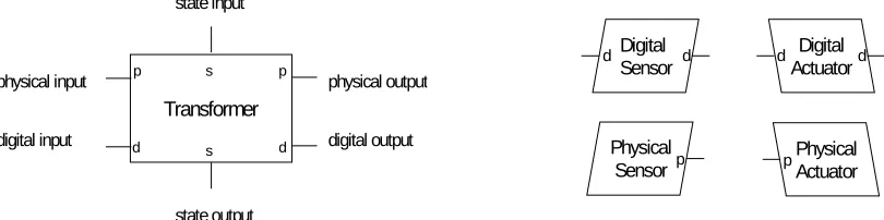
The architectural style distinguishes three component types: sensors, actuators, and transformers. Sensors model input into the system while actuators model output. The key component is the transformer. It is the only component that can perform processing. A transformer receives inputs from one or more sensors, converts them and sends the results to other transformers or actuators. Components communicate by generating events which are transported by connectors. Each component has a set of labelled input and output ports for receiving and sending events, respectively. Connectors are used to join input and output ports of different components. However, connectors can only join ports with the same label. Events are delivered anonymously: a component that generates an event does not know to which components it will be delivered. Routing of events is determined by how components are joined together by connectors. Events automatically travel from the output port of one component to the input port of all connected components.
The left side of Figure 2 shows the structure of a transformer. It has three input and three output ports, labelled p, d and s. p stands for physical input/output, d stands for digital input/output and s stands for state input/output. s ports represent state variables that are accessible by other components. In the diagrams we use the convention that input ports are shown on the left side of a component and output ports on the right side.
We distinguish two types of sensors: physical sensors and digital sensors. A physical sensor is a component that monitors a particular state of the physical environment. Examples include temperature and load sensors. A digital sensor monitors the state of an external system component such as a legacy system such as a web server or database. Similar to sensors, we distinguish between physical actuators and digital actuators. A physical actuator models output that is immediately observable by a user. Examples of physical actuators are: lights, speakers, and displays. A digital actuator is a component that changes the state of an external system.
The right side of Figure 2 shows the structure of sensors and actuators. Digital sensors and actuators have one input and one output port, while physical sensors and actuators have only one out and one input port, respectively.
Transformer
p p
d d
s
s
state input
state output
physical output
digital output physical input
digital input
Physical
Sensor p
Digital Sensor
d d Digital
Actuator
d d
[image:4.595.88.493.57.158.2]Physical Actuator p
4.2 Connectors
Connectors bind components together into a specific configuration. We define two types of connectors: data channels and constraints. Data channels model the flow of data from sensors through transformers to actuators. Constraints model communication between transformers related to state information. Data channels can only be connected to the d and p ports of sensors, actuators and transformers. They are unidirectional: events carrying data travel in one direction from the producer to the receiver. Constraints synchronize state variables of two transformers. They are bi-directional and can only be connected to the s ports of transformers.
The result of using two different connector types is that there are two separate flows of information in a system:
1. A horizontal flow dedicated to transforming input into output.
2. A vertical flow dedicated to inter-component synchronization.
Connectors are abstract elements for modelling communication. They may be realized by different
mechanisms such as procedure calls or events.
4.3Assemblies
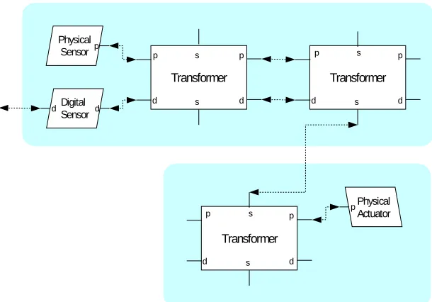
Assemblies are collections of components that model physical boundaries. They are the level on which structural chances within a system can occur. Assemblies may be added to or removed from a system in there entirety, but they must not be broken up. Of course, removing or adding an assembly might change the overall system behaviour. For example, we model an augmented piece of furniture as an assembly. This indicates that moving this furniture piece in and out of an environment is a normal change that the system is expected to handle. However, taking the furniture apart is not.
To facilitate composition of a system out of a collection of assemblies, assemblies may only communicate via constraints. In other words, two transformers connected by a data channel must be contained in the same assembly. Thus a set of assemblies connected by constraints form a constraint network. Figure 3 shows an example of two communicating assemblies; each assembly is visually represented as a shaded box.
Web Server
Traffic Sensor
i o
Light i
Light i
Light i Transformer
p p
d d
s
[image:5.595.148.453.56.269.2]s
Figure 4. Initial Architecture Configuration of Ambient Web Monitor Transformer
p p
d d
s
s
Physical Sensor p
Digital Sensor
d d
Transformer
p p
d d
s
s
Physical Actuator
p
Transformer
p p
d d
s
[image:5.595.133.457.606.757.2]s
4.4 Composition Rules
We now summarize the composition rules for components, connectors and assemblies:
Rule 1: Data channels may be used to connect d and p ports of sensors, actuators and transformers. One out port may be connected to exactly one in port (unicast) or more than one in ports (multicast).
Rule 2: Constraints may be used to connect s ports of two transformers.
Rule 3: An assembly may contain one or more components. Each component may only be part of one assembly.
Rule 4: Only constraints, data channels connected to the in port of digital sensors and data channels connected to the out port of digital actuators may cross assembly boundaries. This rule guarantees that inter-assembly communication only occurs through constraints.
5. MODELLING THE AMBIENT WEB MONITOR ARCHITECTURE
In this section, we demonstrate the utility of the architectural model by discussing two architectures for the Ambient Web Monitor. The first architecture failed to exhibit the required flexibility as described earlier. In the following, we will only present one configuration for each architecture rather than listing all possible configurations.
5.1 Initial Architecture
The initial architecture uses a centralized architecture; all processing is done on a web server that communicates wirelessly with external lights. A configuration of the initial architecture with three posters is depicted in Figure 4. There is one traffic sensor that monitors several URLs. Whenever a page is visited, the traffic sensor sends an event to the transformer. The
transformer manages all connected lights. Periodically, it computes a new page activity level for each monitored URL and derives new light intensities. If a light intensity significantly differs from its previous level, the transformer sends the new light intensity event to the corresponding light actuator. Web server, traffic sensor and controller are contained in one assembly, that is, they represent one physical unit.
5.2 Evaluation of Initial Architecture
The initial architecture fairs rather poorly when it comes to supporting the change scenarios listed in Section 2. Scenarios 4 to 7, which concern individual components, all require internal modifications of the traffic sensor and/or the controller by a programmer. Adding or removing a poster is not possible by simply adding or removing a physical entity.
Scenarios 1 to 3, which concern the entire systems as a whole, are similarly poorly supported. Setting up the web monitor requires access to the web server in order to install software for traffic sensor and controller. Moving the entire system to a new location requires either a physical move of the web server or a fresh installation of the web monitor software on a new web server. In sum, there is no correlation between the physical architecture of the system and the user’s conceptual view of the system. The architecture does not afford the required change scenarios. The results of our architecture evaluation are shown in Table 3.
5.3 Improved Architecture
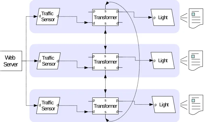
The improved architecture consists of self-contained light objects with their own sensor, transformer, and actuator. Thus, lights and posters can easily be added or removed without requiring software modifications.
A configuration of an Ambient Web Monitor system with three posters is depicted in Figure 5. For each poster, the system contains one assembly with one Traffic
Sensor
Traffic Sensor
Light
Light Light
Web Server
Traffic Sensor d
d
d d
d
d
p
p
p Transformer
Transformer Transformer
p p
d d
s
s
p p
d d
s
s p p
d d
s
[image:6.595.125.470.49.256.2]s
transformer, one digital sensor and one physical actuator. Each sensor monitors the web activity of one particular web page. Whenever a page is visited, the corresponding traffic sensor sends an event to its transformer. Periodically, the transformer computes a new page activity level and derives from that a new light intensity. If the new light intensity significantly differs from the previous level, the transformer sends a new light intensity event to the actuator.
The three transformers are connected to each other by constraints. They guarantee that their state variables stay synchronized. The state variables of the transformers and event types of this architecture are summarized in Table 2. Each transformer maintains two state variables s1 and s2. s1 is the time interval over which the traffic data is aggregated. A value of 60 min indicates that the intensity of the light corresponds to the number of page hits per hour. s2 is the update frequency of the light. A value of 10 seconds indicates that the light intensity is adjusted every 10 seconds.
5.4 Evaluation of Improved Architecture
The assemblies in this configuration indicate direct support for two distinct manipulations:
1. Removing a transformer together with the connected sensor and actuator;
2. Adding a transformer together with a sensor and an actuator.
As result, scenarios 4 to 7 can be performed by physically manipulating assemblies. For example, a user can add a new poster by simply adding a new sensor – transformer – actuator assembly. The constraints between assemblies guarantee that the state variables of transformers are synchronized. This is important because the state variables determine the visible behaviour of the system. Because of the use of constraints existing system components do not need to be updated or reconfigured: the new assembly is automatically integrated into the system.
Scenarios 1 to 3 are also better supported as in the initial architecture. However, we need to make an additional assumption, which is not expressed in the architecture description: installing, moving and removing a web monitor system is simple and can be performed by the
user if a web server is available with a publicly accessible log file. If this is the case, then the user can set up a new system simply by hanging up a poster and attaching a sensor – transformer – actuator assembly.
The improved architecture also supports change scenario 8, the bringing together of two previously separate web monitor systems. Let’s assume there are two Ambient Web Monitor installations in two separate buildings and each installation contains several posters. One installation is set up to use a one hour time interval as parameter and the other is set up to use a 24 hour time interval. Obviously, the light intensities will be different for both installations even if the real web traffic is the same. However, since they are physically apart this does not matter. Let’s further assume both installations will be merged and physically moved into the same room. To make sense to the user, all displays need to use the same parameters. This is guaranteed by the constraints between the transformers.
In sum, the improved architecture shows a correlation between the physical architecture of the system and the user’s conceptual view of the system. To a large extent, the architecture does afford the required change scenarios.
6 IMPLEMENTATION
The improved version of the Ambient Web Monitor has been implemented with the help of the Smart-It embedded device platform [Gellersen et al (18)]. Each transformer is realized as an embedded device to which sensors and actuators are added. Communication between transformers, and to and from external systems is performed via a short-range wireless network. Transformer devices run software for handling communication and for computing updates to state variables.
Currently, constraints must be implemented manually by the programmer; there is no high-level support provide by the embedded devices software platform. Each constraint variable requires the implementation of its own dedicated constraint network. In the future, we plan to investigate generic constraint network implementations for wireless embedded device
TABLE 2. State Variables and Event Types
State Variables Events
Traffic sensor - d: Page hit
Light - -
Transformer s1: Time interval (e.g. 60 min)
platforms. Constraint relationships should be automatically established between devices that are within communication reach and the name of state variables (s1, s2) should be used to auto-establish constraint relationships. Updates to constraint variables will then be broadcast over the network. To prevent cascading updates and endless loops, updates will contain a logical time stamp. The time stamp will be derived from the distributed clock implementation that is part of the network software.
7 RELATED WORK
Change is a key aspect of intelligent environments. In the following we will discuss how physical change resilience is addressed in context-aware systems and platforms. We will then provide an overview of existing approaches from other disciplines such as configuration management, dynamic software architecture, and reconfigurable distributed system.
Context-Aware Computing. Research in ubiquitous and context-aware computing has for the most part focused on the pre-deployment phases of the software lifecycle such as design and implementation. Nevertheless, several context-aware computing platforms provide mechanisms for supporting limited forms of evolutionary changes. For example, the Context Toolkit [Dey et al (19)] and Context Fabric [Hong and Landay (20)] support the swapping of components at runtime. However, they do not target embedded device platforms and they do not allow designers to specify the changes that a system built with these platforms can be expected to accommodate. Furthermore, these platforms have no notion of physical components and thus lack of the concept of physical reconfiguration which we consider essential for intelligent environments.
The architecture for context aware computing by Crowley et al. (21) is one of the few attempts at designing a generic architecture for context-aware systems. The architecture is based on reconfigurable components and is able to express certain structural changes. Yet, again, it lacks the notion of physical components and physical reconfiguration. In addition, it is best suited for input-rich context-aware systems, and less suited for output-only systems.
Dynamic Software Reconfiguration. Kramer and Magee (8) have pioneered the idea of dynamic software reconfiguration for distributed systems. The purpose of dynamic reconfiguration is to make a system evolve incrementally from its current configuration to another configuration while introducing as little impact as possible on the system execution. Kramer and Magee’s focus is to increase the availability of distributed systems. They do that, however, not from an architecture point of view, but they work with a system’s code base. The changes they consider originate in a system’s operating environment and may lead to disruptions of a system’s normal operation. Our work, in contrast, is architectural and concerned with changes induced by end users that occur normally as part of the daily interaction with a system.
In Kramer and Magee’s approach, a system is seen as a directed graph whose nodes are the entities and whose arcs are connections between entities. Entities can only affect each other states via transactions. In our approach we limit component interactions to constraints. In addition, a vital aspect of our work missing from Kramer and Magee is the explicit representation of structural changes as part of the architecture.
Dynamic Software Architectures. Allen et al (6) were the first to consider dynamic software architectures. There main interest is to develop an architecture description language (ADL) that is capable of TABLE 3. Summary of Architecture Evaluation
Change scenario Initial
Architecture
Improved Architecture
1. Setup system for the first time - o
2. Move system to new location - o
3. Remove system from location - o
4. Move component to new location - +
5. Remove component from system - +
6. Add new component to system - +
7. Replace component with another
version - +
representing certain structural modifications. Their approach is heavily geared towards developing a semantic foundation for their language; they are not at all concerned with identifying which types of changing might be most important from a user’s point of view. Van der Hoek et al (7) follow a more pragmatic approach by examining the relations between software architecture and software configuration management. They propose a novel representation, called configurable software architecture, which extends the traditional notion of software architecture with the concepts of variants, options and evolution. Similar in scope to our fluid architecture model, they focus on architectural changes that may be performed by developers as part of ongoing development activities. Our work, in contrast, is driven by user-level usage scenarios. Furthermore, similar to work in dynamic software reconfiguration they do not consider the physical boundaries as vital change aspect.
Self-healing and Self-adaptive Systems. Software architecture specifications can serve many purposes beyond simply functioning as a means for communication between stakeholders. Work on self-healing and self-adaptive systems (14)(15) uses architecture to make decisions about run-time adaptation by comparing monitored and expected system state. However, the current work in this area focus on behaviour adaptation as opposed to user-induced structural modifications. Similarly, it has not yet been applied to context-aware and embedded systems. Many of the techniques and methods, however, apply to intelligent environments and we plan to investigate them as outlined below.
End user configuration. An interesting alternative to our approach was proposed by Humble et al (22). Instead of trying to shield the user from the knowledge that reconfiguration takes place and the knowledge of how reconfiguration is performed, they aim to put user in control of the configuration task. To that end, they have developed a graphical editor for a PC that users can use to reconfigure their environment at will. This assumes that users are willing to reconfigure their pervasive computing environment and knowledgeable enough to understand the consequences of their actions.
8 CONCLUSION AND FUTURE WORK
Intelligent environments emerge when we augment physical objects and environments with computation, sensing, and communication. These systems have a physical nature, they are dispersed in space, and they mediate between the physical and digital world. A key requirement of intelligent environments is that they are change resilient with respect to physical reconfiguration. These changes are induced by the user and are part of the normal and expected usage pattern.
The key contribution of this paper is an architectural model for fluid intelligent environments that allows designers to specify the range of physical reconfiguration supported by an architecture. The model defines a fluid architecture as a (possibly infinite) set of alternative system configurations. Each configuration represents one possible architectural state. Each configuration consists of a set of components bound together by connectors. Data channels are used to model the transformation from sensor input into output for actuators. Component assemblies are used to represent physical boundaries within the system. By limiting communication between assemblies to constraints, we achieve a conceptually simple model for physical composition that is easy to implement.
The main focus of our work so far has been to investigate change requirements for intelligent environments and to develop an architectural model that allows designers to capture important change dimensions. Our future work aims to answer the following two questions:
§ Is it possible to derive an implementation of an intelligent environment from high-level models? In particular, we are interested in applying recent results from research on model-driven software development.
§ Is it possible to add self-awareness to an intelligent environment such that it knows when it is in a legal or illegal state? How can this be done in a decentralized ad-hoc environment consisting of resource-limited wireless embedded devices?
ACKNOWLEDGEMENTS
This work has been supported by the EU project CoBIs (IST 004270) and the UK Engineering and Physical Science Research Council (EPSRC) project NEMO (EP/C014677/1).
REFERENCES
1. M. Weiser 1994. Creating the Invisible Interface, Proc. 7th Ann. ACM Symp. User Interface Soft-ware and Technology, ACM Press, 1994, p. 1.
2. D. Garlan, D. Siewiorek, A. Smailagic, and P. Steenkiste 2002. Towards Distraction-Free Pervasive Computing, by, IEEE Pervasive Computing, special issue on "Integrated Pervasive Computing Environments", Volume 1, Number 2, April-June 2002, pages 22-313
4. Paul Dourish 2001. Where the Action Is. The Foundations of Embodied Interaction. MIT Press. October 2001
5. T. Rodden and S. Benford 2003. The evolution of buildings and implications for the design of ubiquitous domestic environments. Conference on Human Factors and Computing Systems (CHI 2003), Ft. Lauderdale, Florida, USA, 2003.
6. R. Allen, R. Douence, and D. Garlan 1998. Specifying and analyzing dynamic software architectures. In Proc. FASE'98, Springer Lect. Notes in Comp. Sci. 1328, 1998
7. André van der Hoek, Dennis Heimbigner, Alexander L. Wolf 1999. Configurable software architectures: Capturing Architectural Configurability: Variants, Options, and Evolution. Technical Report CU-CS-895-99, Department of Computer Science, University of Colorado, Boulder, Colorado, December 1999.
8. J. Kramer and J. Magee. Dynamic Reconfiguration for distributed systems. IEEE Transactions on Software Engineering 11(4), pp. 424-436, April 1985.
9. H.-W. Gellersen, A. Schmidt 2002. Look who's visiting: supporting visitor awareness in the web. International Journal of Human Computer Studies IJHCS 56(1), January 2002. pp. 25-46.
10. D.E. Perry and A.L. Wolf. Foundations for the Study of Software Architecture. ACM SIGSOFT Software Engineering Notes, 17(4):40-52, October 1992.
11. D. Garlan and M. Shaw. An Introduction to Software Architecture: Advances in Software Engineering and Knowledge Engineering, vol 1. World Scientific Publishing, 1993.
12. S.-W. Cheng, D. Garlan, B. R. Schmerl, J.P. Sousa, B. Spitznagel, P. Steenkiste, N. Hu. Software Architecture-Based Adaptation for Pervasive Systems. Proceedings of the International Conference on Architecture of Computing Systems: Trends in Network and Pervasive Computing, 2002, Pages: 67 – 82.
13. D.E. Perry and A.L. Wolf. Foundations for the Study of Software Architecture. ACM SIGSOFT Software Engineering Notes, 17(4):40-52, October 1992.
14. D. Garlan, and B. Schmerl. Model-based Adaptation for Self-Healing Systems," ACM SIGSOFT Workshop on Self-Healing Systems (WOSS'02), November 18-19, 2002
15. D. Garlan, S-W Cheng, and B Schmerl, Increasing System Dependability through Architecture-based Self-repair, in Architecting Dependable Systems, R. de Lemos, C. Gacek, A. Romanovsky (Eds), Springer-Verlag, 2003
16. P. Oreizy, M. M. Gorlick, R. N. Taylor, D. Heimbigner, G. Johnson, Nenad Medvidovic, A. Quilici, D.S. Rosenblum, A. L. Wolf. An Architecture-Based Approach to Self-Adaptive Software. IEEE Intelligent Systems, Volume 14, Issue 3 (May 1999), pages: 54 – 62.
17. .G. Abowd, R. Allen, and D. Garlan. Using Style to Understand Descriptions of Software Architecture Proceedings of SIGSOFT '93: Symposium on the Foundations of Software Engineering, December, 1993.
18. H. Gellersen, G. Kortuem, A. Schmidt, M. Beigl 2004. Physical Prototyping with Smart-Its, IEEE Pervasive Computing, July-September 2004 (Vol. 3, No. 3) pp. 74-82
19. Dey, A. K., Salber, D., Abowd, G. A conceptual framework and a toolkit for supporting the rapid prototyping of context-aware applications. Human-Computer Interaction, Vol. 16, 2001.
20. J. I. Hong and J, A. Landay, An Infrastructure Approach to Context-Aware Computing." In Human-Computer Interaction, 2001, Vol. 16.
21. J. L. Crowley, Joëlle Coutaz, Gaeten Rey, Patrick Reignier. Perceptual Components for Context Aware Computing. Proceedings 4th International Conference on Ubiquitous Computing (Ubicomp 2002), pp 117-134, September/October 2002.