Received August 15, 2019; Revised December 17, 2019; Accepted December 24, 2019
Copyright©2019 by authors, all rights reserved. Authors agree that this article remains permanently open access under the terms of the Creative Commons Attribution License 4.0 International License
Abstract
The purpose of this paper is to design a new concept of an automatic compaction device for composite panel production at layup process in one of the aircraft composite panel manufacturers in Malaysia, known as Company A. The current compaction process in company A requires an implementation of an effective and automatic vacuum bagging/compaction process to replace the current manual way method. The objective is to implement an automatic device to be integrated with the current method in order to make it simpler and more efficient for the operators to do the compaction process. This method could avoid human error in compaction timer hence reducing completed panel defect rate. Vacuum bagging/compaction process is a very important process to consolidate the laminates into a composite. Hence it is important for the precision of vacuum pressure and timing for the compaction process. The automatic device is designed to do the compaction process according to the timer automatically. The approach of designing this device is to use timer and solenoid valve to control the vacuum and a timer with a microcontroller. This device implementation will also reduce the steps of compaction process compared to the current way of doing so in Company A. In addition, it is believed to reduce the redundancy of work of the operators and increase multitasking of the operator and yield of composite panel produced by the company.Keywords
Automatic Compaction Device, Composite Panel Compaction, Vacuum Bagging, Lay-up Process, Arduino Microcontroller1. Introduction
A composite material is the product of two or more natural or artificial elements to become a stronger material as a whole. Its characteristic now has the combination of the elements with added strength, efficiency and durability. Composite material is made by combining fibre and matrix. The role of fibre is to provide strength and stiffness to the material, for example glass, carbon and aramid. The matrix of composite material is either plastic or resins like polyester, vinyl ester or epoxy. It provides shape to the material and protects the fibres from damage. The reinforced fabric or fibre which is pre-impregnated with partly cured resin beforehand is also known as prepreg [1]. In most cases, there is also a honeycomb core material sandwich in between the composite materials. The core can be made of Kevlar or fibreglass which gives extra strength and durability to the composite itself. Application of composite material is used as parts or components in aerospace industry, racing industry and many more.
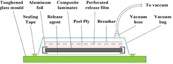
Figure 1. Compaction (vacuum bagging) process
Vacuum bagging is a technique to consolidate all the materials by using mechanical pressure to compress, and most importantly to hold the lamination together firmly. This technique is to remove trapped air in between layers which are important before sending the lamination to an autoclave for curing cycle. This is because trap air may reduce the efficiency and physical properties of a composite material by reducing the force transfer or shifting the orientation between fibre and resin [1]. To further control the quality of the composite material, the whole layup process including vacuum bagging is done in a control contamination area to prevent contamination such as dust and humidity. As there are some other techniques, vacuum bagging is especially beneficial for complex shapes, structure with core materials and autoclaves with prepregs [1].
Vacuum bagging is one of the very effective ways of producing good quality composite, but there is bound to be some area that can be improved. This project dwells into the difficulties and challenges in vacuum bagging. The vacuum bagging technique in general is done manually by human even in some bigger production companies. The operator had to connect a vacuum source to the bagging film to compact the lamination after every material sheet is layup. The vacuum process will take several minutes for the pressure level to reach the targeted value. After that, the operator had to remove the vacuum and put on a pressure gauge to take the reading. The gauge is also left there for several minutes to check the pressure level whether it is still maintained at that desired level. If the level is not achieved, which means there are leaks or faulties in the lamination. The lamination needs to be redone again. If there is nothing wrong, the gauge is removed and continues with the rest of the layup process. This process is repeated until all plies are put together. After that, final bagging will be done in a similar way to check for overall pressure of the lamination. If the pressure level is suitable, the vacuum will be connected again regardless of time until moving to autoclave for curing cycle. The purpose is to maintain the pressure level while waiting for the curing process.
It can be seen that a simple task required a lot of attention from human. The operator is required to
constantly check the compaction process, by removing and applying the vacuum. The individual is also required to keep track of the time duration by looking at the clock or stopwatch when applying vacuum and gauge to maintain the desired pressure level. It is tedious and repetitive work which can be done automatically. In a case study carried out at an aircraft composite panel manufacturer (Company A), the operators can only manage one or two normal size composite panel at a time. There are ways which may increase the efficiency in vacuum bagging to produce composite materials such as automation.
This project is to come out with a device which is mainly used to automatically turn on and off the vacuum during vacuum bagging/compaction process. This is also to assist the operator on dealing with repetitive task where human error tends to increase in repetitiveness. By reducing the human error, every lamination can be ensured to be produced in high quality while following the resident work plan (RWP) / SOP requirement. The three main objectives of this project are to improve the current manual compaction method into automatic timer method, to design and build an automatic compaction device (hardware) and to design a simple user interface and a timer on the device by using IoT based software.
2. Methodology
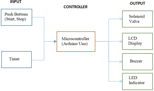
Figure 2. Input, output & controller of the automatic compaction device
Figure 3. Automatic Compaction Device Layout.
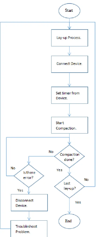
Figure 4 shows the flowchart on how the automatic compaction device works. The LCD will light up when it is turned on and the operator is now required to give input to the device by pressing the buttons. The LCD will prompt a simple UI for user to select a timer suitable for different specification of compaction required on different composites according to the RWP of Company A, for
up and buzzer is on. This means one cycle of compaction is completed.
After one cycle is done, the operator may proceed to the next layup process and compaction loop by pressing selecting the timer again until the whole compaction process is done. If there is fault in the lamination or any technical error, the operator may press the start/stop button again to stop the process while turning off almost every output including the valve and most of the LEDs. Only the red LED will light up and the LCD will display ‘Manual Mode’ to indicate the manual process that has been initiated. The purpose of this process is to allow operator to check for leaks or redo the laminate layup manually. This is to ensure there are still ways to revert to manual compaction while there is error for easy troubleshooting process. After troubleshooting, to restart back the
implementation and the result will be discussed in the following chapter. The concept of this device is to improve the current manual method of doing vacuum bagging/compaction in Company A to more automated method.
3. Result and Discussion
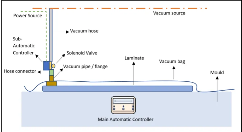
[image:5.595.96.497.419.638.2]Figure 5 shows the vacuum bagging/compaction connection layout in Company A’s production line when the automatic compaction device is installed. The connection is the similar as the current connection in the company but with the addition of the automatic controller device and a solenoid valve attached to the vacuum hose.
A vacuum hose is connected to the vacuum source which is a centralized system. In the current system, the operator will pull the vacuum hose with a hose connector to connect to the vacuum pipe. The vacuum pipe is attached to the vacuum bag where the bag covers and seals the laminate. This is how the compaction of the lamination can be done. Then, the hose needs to be removed and a gauge is connected to a pipe to measure the pressure level. This is the current manual way of doing the compaction in Company A. In an improved device, a solenoid valve with a sub-controller will be inserted between the hose and pipe to act as opening and closing of the vacuum flow automatically. Besides that, the main automatic controlling device with LCD located near the working station will show the timer and status.
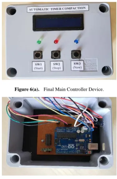
Figure 6(a) shows the prototype of an automatic compaction device. The components used should be able to simulate the function of the actual component which is to be used in the final device hardware. The 7-segment display is easy to code as a countdown timer compared to the LCD display. The servo motor requires low voltage to run which is suitable to run directly from the Arduino board. Unlike the solenoid valve, it requires much higher voltage which requires additional components like a transistor and relay to operate and to protect the circuit.
Figure 6(a). Final Main Controller Device.
Figure 6(b). Final Circuit of Main Device.
The main controller circuit with the Arduino microcontroller in the automatic compaction device is shown in figure 6(b). The input buttons, LEDs and LCDs are included in this main section of the device. In this device, there are also the RF transmitter module and the
encoder IC module. The purpose of these two components is to transmit data to their counterpart in the sub-controller wirelessly (as shown in figure 7). It could be seen that the whole circuit and components are enclosed in a PVC junction box while showing only the inputs and outputs which are the three pushbuttons, LEDs and the LCD. This is to protect the circuit and components during implementation in production line and for a finished product appearance.
The Arduino microcontroller is the brain of the whole system. It receives feedback from the input pushbuttons and controls the LEDs, LCD and the RF transmitter to transmit data to the sub-controller wirelessly to control its output. The LEDs act as indicators for the user to identify the status of the device. The LCD mainly displays the user interface and the timer. The encoder encodes the data from the microcontroller and then the RF transmitter will transmit the encoded signal to the RF receiver in the sub-controller device. Since there is no microcontroller in the sub-device, that is why it requires the encoder and decoder IC module pair to transmit signal along with the RF module pair. All the components are supplied with not more than 5V from Arduino itself.
Figure 7(a) and 7(b) show the sub-controller hardware part of the automatic compaction device system. The main components included in this device are the decoder IC module, RF receiver module, two relays, buzzer and the solenoid valve. The circuit and components are enclosed in a smaller PVC junction box. Just like the main device, the box is to protect the circuit and give the look of a finished product. The solenoid valve and buzzer are connected outside of the box.
Figure 7(a). Final Sub Controller Device
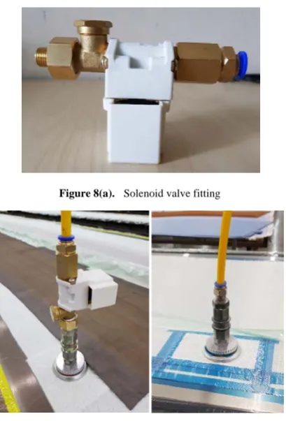
[image:6.595.79.267.384.672.2] [image:6.595.320.521.479.662.2]or adaptor is put on the solenoid valve to connect it to the vacuum pipe. There is a sample vacuum pipe obtained from the company as a reference to buy the fitting connectors. The vacuum pipe or flange sits directly on top of the composite material. With the proper fittings as shown in figure 8(a), then the solenoid valve could be installed onto the current vacuum system shown in figure 8(b).
Figure 8(a). Solenoid valve fitting
Figure 8(b). Vacuum hose with and without valve
4. Conclusion
In order to improve the current redundant way of compaction in Company A, a concept of automatic compaction device with solenoid valve to turn on and off could improve the situation. The design and the prototype of automatic compaction device have been successfully fabricated and tested. There are two parts of the automatic device which is the main controller with LCD, LEDs and buttons and a sub-controller with the solenoid valve and
REFERENCES
[1] Gougeon Brothers Inc., "Vacuum Bagging Techniques," April 2010. [Online]. Available: https://www.westsystem.com/wp-content/uploads/Vacuum
Bag-7th-Ed.pdf. [Accessed 14 Oct 2018].
[2] G. Francucci, S. Palmer and W. Hall, "External compaction pressure over vacuum-bagged composite parts: Effect on the quality of flax fiber/epoxy laminates," Journal of Composite Materials, vol. 52, no. 1, pp. 3-15, 2017.
[3] M. L. Aparna, G. Chaitanya, K. Srinivas and J. A. Rao, "Fabrication of Continuous GFRP Composites using Vacuum Bag Moulding Process," International Journal of Advanced Science and Technology, vol. 87, pp. 37-46, 2016.
[4] B. D. Agarwal, L. J. Broutman and K. C. Sekahara, "Analysis and Performance of Fiber Composites," Applied Mechanics, 2006.
[image:7.595.74.279.298.600.2]