OUTER-ROTOR HYBRID EXCITATION FLUX
SWITCHING GENERATOR FOR GRID
CONNECTED WIND TURBINE APPLICATIONS
ABDIFATAH MOHAMUD ARAB
UNIVERSITI TUN HUSSEIN ONN MALAYSIA
STATUS CONFIRMATION FOR MASTER’S THESIS
FUNDAMENTAL STUDY AND OPTIMIZATION OF OUTER-ROTOR HYBRID EXCITATION FLUX SWITCHING GENERATOR FOR GRID
CONNECTED WIND TURBINE APPLICATIONS ACADEMIC SESSION : 2015/2016
I, ABDIFATAH MOHAMUD ARAB agree to allow this Master’s Thesis to be kept at the Library under the following terms:
1. This Master’s Thesis is the property of Universiti Tun Hussein Onn Malaysia. 2. The library has the right to make copies for educational purposes only.
3. The library is allowed to make copies of this report for educational exchange between higher educational institutions.
4. ** Please Mark (√)
CONFIDENTIAL
(Contains information of high security or of great importance to Malaysia as STIPULATED under the OFFICIAL SECRET ACT 1972)
RESTRICTED (Contains restricted information as determined by the Organization/institution where research was conducted)
FREE ACCESS
_________________________
Approved by,
__________________________
(WRITER’S SIGNATURE) (SUPERVISOR’S SIGNATURE)
Permanent Address : H.NO; 08, Goljano Street
Codominium, Hargesia,Somaliland Date: ___________________
Supervisor’s name
DR. ERWAN BIN SULAIMAN
Date : ________________________ NOTE:
** If this Master’s Thesis is classified as CONFIDENTIAL or RESTRICTED, Please attach the letter from the relevant authority/organization stating reasons and duration for such classifications.
26 JANUARY, 2016
FUNDAMENTAL STUDY AND OPTIMIZATION OF HYBRID EXCITATION FLUX SWITCHING GENERATOR FOR GRID CONNECTED WIND TURBINE
APPLICATIONS
ABDIFATAH MOHAMUD ARAB
A thesis submitted in
Fulfillment of the requirement for the award of the Degree of Master of Electrical Engineering
Faculty of Electrical & Electronic Engineering Universiti Tun Hussein Onn Malaysia
ii
I hereby declare that the work in this thesis is my own except for quotations and summaries which have been duly acknowledged.
Student : ………
ABDIFATAH MOHAMUD ARAB
Date : ……….
Supervisor : ………. DR. ERWAN BIN SULAIMAN
DEDICATION
To my mother and father
iv
ACKNOWLEDGEMENT
Thoughtful gratitude is given to the Almighty ALLAH, the creator of the universe in whom we breathe and have our being for diligently guiding us through this practical training and our academic life up to this point of completion of my master degree studies.
I also wish to express my gratitude to my supervisor, Dr. Erwan Bin Sulaiman for his excellent guidance, ideas, advice and patience during this project. Without his constructive and critical comments, continues encouragement and good humor while facing difficulties, I could not have completed this research work. I am also very grateful to him for guiding me to think independently.
Without support from technical staff and my lab fellows of FSM research group, this research would not have been undertaken. My sincerely thanks to all my FSM group friends who helped me every time with their technical knowledge.
It is always very pleasant and enjoyable to work in UTHM with a group of highly dedicated people, who have always been willing to provide help, support and
encouragement whenever needed. I would like to thank all my lecturers and friends during my journey of study in UTHM. Life would have never been that existing and joyful without you.
ABSTRACT
Effective generation of energy enables commercial and industrial facilities to minimize production costs, increase profits, and stay competitive. Most of electrical energy consumed in industrial facilities is received from electrical generators. Therefore it is necessary to perform research in order to develop advanced electric generators with less cost and high efficiency.There has been a recent interest in flux switching generators (FSG) in which all the flux sources are positioned in the stator that make the rotor simple, robust and brushless. Hence, this project presents an operating principle of a new proposed outer-rotor hybrid excitation flux switching generator. In this Generator a combination of a permanent magnet (PM) and field excitation coil (FEC) are used as the main flux sources. Additional FEC can be used to control the flux so that constant voltage can be produced at various wind
conditions. Moreover, twelve coil tests, Three Phase coil test flux excited by PM only, Back-EMF at various speed and stack-length conditions, magnetic flux
vi
ABSTRAK
Penjanaan tenaga yang berkesan membolehkan kemudahan perdagangan dan
perindustrian untuk mengurangkan kos pengeluaran, meningkatkan keuntungan, dan kekal berdaya saing. Kebanyakkan tenaga elektrik yang digunakan dalam industri diterima daripada penjana tenaga elektrik. Justeru itu, penyelidikan terhadap penjana tenaga elektrik yang lebih mendalam pada masa hadapan haruslah dilaksanakan untuk menjimatkan kos dan meningkatkan kecekapan. Terdapat beberapa kajian dalam penjana pensuisan fluks (FSG) di mana semua sumber fluks diletakkan dalam pemegun yang membuat pemutar ringkas, mantap dan tanpa berus. Oleh itu, projek ini memberi satu prinsip operasi yang mencadangkan luar pemutar pengujaan hibrid penjana tenaga pensuisan fluks. Penjana tenaga ini menggabungkan magnet kekal (PM) dan pengujaan medan gegelung yang digunakan sebagai sumber fluks utama. FEC tambahan boleh digunakan mengawal fluks supaya voltan yang berterusan boleh dihasilkan dalam pelbagai keadaan angin. Selain itu, dua belas ujian gegelung, tiga fasa ujian gegelung fluks teruja dengan PM sahaja, Back-EMF di pelbagai kelajuan dan panjang, pengukuhan fluks magnet di pelbagai ketumpatan arus dan pengedaran fluks dikaji dengan menggunakan perisian JMAG. Hasil kajian menunjukkan bahawa voltan yang dihasilkan adalah berkadar terus dengan perubahan kelajuan dan panjang. Saiz reka bentuk yang lebih baik telah dihasilkan dan 7.4 kali ganda daripada reka bentuk asal. Selain itu, salah satu lagi teknik untuk
TABLE OF CONTENTS
DECLARATION ii
DEDICATION iii
ACKNOWLEDGEMENT iv
ABSTRACT v
ABSTRAK vi
TABLE OF CONTENTS vii
LIST OF TABLES x
LIST OF FIGURES xi
LIST OF PUBLICATIONS xiv
LIST OF AWARDS xiv
CHAPTER 1 INTRODUCTION 1
1.1 Research Background 1
1.2 Problem Statement 3
1.3 Objectives of the Study 3
1.4 Scope 3
1.5 Thesis outline 4
CHAPTER 2 LITERATURE REVIEW 5
2.1 Introduction 5
viii
2.5 Design of high performance permanent-Magnet
synchronous wind Generator 11
2.6 Design Dimension of the Rotor 12
2.7 Optimal sizing of Rotor Magnet 16 2.8 AC Generator Construction 17 2.9 Principles of AC Construction 18 2.10 AC Generator Function 19 2.11 Principles of Operation of synchronous Machines 20
2.12 Electricity 22
2.13 PM Synchronous Machine 23
2.14 Radial Flux or Axial Flux 24
2.15 Axial Flux Machines 24
2.16 Longitudinal or Transversal Flux Machines 25
2.17 Inner Rotor or Outer Rotor 26
2.18 No Load Analysis of ORHEFSM 27
2.8.1 Armature Coil Arrangement Test 28
2.19 Design Study of 12Slot-10Poles Outer Rotor HEFSM 29
2.20 Design Improvement of a new ORHEFSM 30
2.21 Experimental Test of a 72Slot-78Pole high Performance PMSG 31
CHAPTER 3 METHODOLOGY 34
3.1 Introduction 34
3.2 Design and Investigation of HEFSG 35
3.3 Introduction to JMAG-Designer Software 38
3.4 Project Design 38
3.5 Project Analysis 39
3.6 Project Design Improvement 40
CHAPTER 4 RESULTS AND ANALYSIS 41
4.1 Introduction 41
4.2 Twelve Coil Arrangement Test 42
4.4 U, V, W 44
4.5 Final Coil Test (clockwise direction) 45
4.6 Cogging Torque Test 45
4.7 Calculation of DC FEC current 46
4.8 Back-Emf versus Rotor position 47
4.9 Flux Strengthening 48
4.10 Magnetic Flux-Linkage and Back-EMF versus FEC Current Densities 48
4.11 Flux Distribution 49
4.12 Speed Impact on B-EMF 51
4.13 Stack-length Impact on B-EMF 51
4.14 Comparison of speed and Stack-length Impact on B-EMF 52
4.15 Design improvement 53
4.16 Deterministic Optimization Method 55
CHAPTER 5 CONCLUSION AND FUTURE WORKS 59
5.1 Introduction 59
5.2 Conclusion 59
5.3 Future Works 60
x
LIST OF TABLES
1.1 Material selection for stator, rotor, armature coil And d FEC 5 1.2 Initial design parameters 5 2.1 Value of Ie when Je equals to 5, 10, 15, 20,25
LIST OF FIGURES
2.1 Proposed structure of outer-rotor HESFG 4 2.2 Classification of main types of generators 6
2.3 Basic schematic of SCIG 7
2.4 Magnetic pole system generated by currents in the stator and
rotor windings 8
2.5 Per-phase equivalent circuit of an induction machine 9 2.6 Doubly-fed induction generation system power flows 10 2.7 Wind power generation using double fed induction 10 2.8 Schema graph of PMSG and magnet dimension:
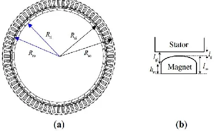
78pole, 72-slot PMSG; (b) magnet dimension 11 2.9 Schematic diagram of permanent-magnet synchronous
(PMSG): Magnetic flux path 12
2.10 A magnetic circuit model for the proposed structure:
(a) Complete magnetic circuit Model; b) simplified model 12
2.11 Relationship between normalized airgap flux density
And permeance coefficient 14 2.12 Relationship between αp-p and air gap flux density:
(a) αp-p = 1; (b) αp-p = 0.5 15 2.13 Induced voltages of PMSG with different αp-p by Maxwell
2D: a) phase voltages b) line voltage 16
2.14 AC Generator Function 17
2.15 Synchronous Machine construction salient-pole rotor 18 2.16 Schematic cross section of a synchronous machine with
A cylinderical round-rotor (turbo generator) 19
2.17 AC Generator Function 20
xii
2.20 Magnet Fields created by current flow in a conductor 22
2.21 Magnetic field produced by the flow of electric current in A coil –shaped conductor 22 2.22 Ionic Clouds of positive and Negative currents 22 2.23 the flow of electons inside a conductor material 23 2.24 Cross sectional view in radial direction and in axial direction, respectively of a typical radial PMSG [24] 24 2.25 Cross sectional in radial direction and in axial direction Respectively of a typical axial flux PMSG [24] 25 2.26 Fraction of a typical transversal flux PMSG 26
2.27 Inner rotor PMSG (left) and an outer rotor PMSG (right) 27
2.28 Armature coil phase setting27 2.29 Three-phase flux linkage generated by PM 28
2.30 Back-Emf at 3000rpm 29
2.31 Flux path of PM only 30
2.32 Design parameters defined as D1- D10 30
2.33 Fundametal back-Emf at 3000rpm 31
2.34 Experimental apparatus: (a) schematic diagram (b) platform photo 32
2.35 Experimental wiring photo 32
2.36 Measured and simulated no-load induced voltages (a) double three-phase winding (b) six phase winding 33
3.37 General work flow of the project implementation 35
3.38 project design flowchart 37
3.39 JMAG Designer 38
3.40 JMAG editor 38
3.41 Design parameters shown as D1- D10 40
3.42 Initial HEFSG design 41
4.43 HEFSG twelve coil arrangement test 42
4.44 Combination of four armature coils that have similar pattern 43
4.45 UVW Circuit 44
4.46 UVW Flux clockwise field test 45
4.48 Back-Emf at various FEC 47
4.49 Flux strengthening versus Electric cycles 48
4.50 Flux linkage and induced voltage versus various Current densities 49
4.51 Comparison of flux paths 50
4.52 Speed effect on B-EMF 51
4.53 Stack-length effect on B-EMF 52
4.54 Back-EMF versus rotor speed and stack-length 53
4.55 Design parameters as shown as D1- D10 54
4.56 Rotor Radius optimization 55
4.57 Rotor width opimization 55
4. 58 Rotor depth optimization 56
4.59 PM width optimization 56
4.60 FEC width optimization 56
4.61 AC Width optimization 57
4.62 AC length optimization 57
4.63 Comparison of initial and improved HEFSG 57
xiv
LIST OF PUBLICATION
proceeding Paper :
Abdifatah M.Arab, Erwan Bin Sulaiman, “Fundamental study of outer-rotor hybrid excitation flux switching generator for grid connected wind turbine applications ”, IEEE Student Conference on Research and Development (Scored 2015) 13-14 December at Berjaya Time Square , Kuala Lumpur
LIST OF AWARDS
(i) Certificate of participation at IEEE Student Conference on Research and Development (Scored 2015), Berjaya Time Square, Kuala Lumpur
CHAPTER I
INTRODUCTION
1.1. Background of Study
With the rapid development of wind power technologies and significant growth of wind power capacity installed worldwide, various types of wind generator systems have been developed. Among the well-known wind generator systems are:-
(i) Permanent magnetic synchronous generator with direct-generators with three-stage
gearbox and single-stage gearbox.
(ii) Electricity excited synchronous generator with direct-driven.
(iii)Variable speed constant frequency squirrel cage induction generator with three-stage and three-single stage gearbox [1] [2].
2
synchronous generator (PMSG), doubly fed induction generator (DFIG), electricity excited synchronous generator (EESG), and squirrel cage induction generator (SCIG) [3].
Squirrel Cage Induction Generators are widely used in wind mills due to the several advantages, such as robustness, mechanical simplicity and low price. the rotor speed of a SCIG varies with the amount of power generated. The generator will always draw the reactive power from the grid. The speed varies over a very small range above synchronous speed as it is coupled with the grid, hence, it is Commonly known as a fixed-speed generator[4].
Moreover, double fed induction generators (DFIG) are also used for wind turbine. They are an induction machines with a wound rotor where the rotor and stator are both connected to electrical sources. They offer several advantages including; they operate at variable rotor speed while the amplitude and frequency of the generated voltages remain constant. Generation of electrical power at lower wind speed, virtual elimination of sudden variations in the rotor torque and control of the power factor in order to maintain the power factor at unity. However, DFIG requires complex power conversion circuitry, the slip rings on the wound router induction machine used to implement the doubly-fed induction generator requires periodic maintenance [5].
1.2. Problem Statement
The increasing demand of a cheaper, low background noise, low loss, less regular maintenance, variable speed and controllable magnetic field wind turbine generators have extremely risen nowadays.
To overcome the drawbacks of constant speed and uncontrollable magnetic field of the permanent magnet synchronous generator, a new outer-rotor hybrid excitation flux switching generator (HEFSG) was proposed in which the combination of permanent magnet (PM) and field excitation coil (FEC) are the main flux sources with direct-driven topology. Additional current densities can be applied to the FEC to control the output voltage.
1.3. Objectives of the study
The objectives of this project are:-
(i) To investigate the operating principle of outer-rotor hybrid excitation flux switching
generator and to confirm the coil phase and the number of turn of each armature coil of the proposed generator for wind turbine generator applications
(ii) To analyse the performances of the proposed generator on the impact of wind speed and stack-length until the target output voltage of 415V is achieved.
(iii)To optimize the parameters of the proposed design and the number of turns.
1.4. Scopes
The scopes of this project will involve simulation using JMAG designer and JMAG editor software. The proposed design will focus on the following areas:-
The new design has a combination of permanent magnet and field excitation coil as the
main flux sources
Additional FEC was used to control the flux so that constant voltage can be produced at
various wind conditions
Analysis result has involved coil test, flux strengthening and weakening, EMF.
Target induced output voltage is 415V
4
Table 1.1: Material selection for stator, rotor, armature coil and FEC [37]
1.5. Thesis outline
A new structure of 3-phase concentrated winding flux switching generator, in which the PM is placed in the stator, was proposed and the structure of the machine is shown in figure.1. Due to the elimination of PM in rotor part, the mechanical strength of the machine is improved and becomes more suitable for low speed high torque wind generator. In addition, the concentrated windings of armature coil reduce the coil end strength, thus reducing the machine weight and copper loss. In order to control the PM flux, DC (FEC) was introduced in such a way that the air-gap field provided by PM can be controlled with variable flux capabilities especially to provide high torque by controlling the direction and magnitude of the FEC current. Since two flux sources namely PM and DC FEC are employed in this machine, the machine is named as hybrid excitation flux switching generator (HEFSG) with outer-rotor configuration.
The proposed wind generator design has the ability to provide output voltage similar to conventional 415V power supply.
Figure1. Proposed structure of outer-rotor HEFSG [8]
Parts Material used
Stator 35H210
Rotor 35H210
Armature coil Copper
FEC Copper
CHAPTER II
LITERATURE REVIEW
2.1. Introduction
One way of generating electricity from renewable sources is to use wind turbines that convert the energy contained in flowing air into electricity. The main advantages of electricity generation from renewable sources are the absence of harmful emissions and the infinite availability of the prime mover that is converted into electricity.
This chapter contains the introduction and the classification of electrical generators. Initially each type of electrical generator is explained. It also explains working principles of each generator.
2.2. Introduction to electrical Generator
6
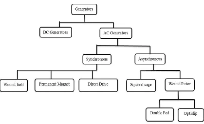
[image:22.612.88.507.213.469.2]of synchronous and Asynchronous, and DC generators just have the subcategory brushed. Brushed DC generators have a lot of maintenance need with the brushes and were quickly eliminated as an option for the wind turbine. Asynchronous and synchronous AC generators have several options, however permanent magnet was chosen because they are often produced with a high number of poles, which allows for a low RPM (revolutions per minute) range, and turbine production without a gearbox, the figure below shows the available options for generators.
Figure 2.1: Classification of main types of generators
2.3. Squirrel Cage Induction Generators
stator winding. SCIG feed only through the stator and generally operate at low negative slip, approximately 1 to 2 per cent. Hence the rotor speed of a SCIG varies with the amount of power generated. The generator will always draw the reactive power from the grid. Reactive power consumption is partly or fully compensated by capacitors in order to achieve a power factor close to unity and make the induction machine to self-excite. The speed varies over a very small range above synchronous speed as it is coupled with the grid, hence
Commonly known as a fixed-speed generator [9].
[image:23.612.136.471.401.602.2]The SCIG is a self-excited induction generator where a three-phase capacitor bank is connected across the stator terminals to supply the reactive power requirement of a load as shown in figure 2.2 and generator was discovered by Basset and Potter in the 1930s. When such an induction machine is driven by an external mechanical power source, the residual magnetism in the rotor produces an Electromotive Force (EMF) in the stator windings[4] [10]. This EMF is applied to the capacitor bank causing current flow in the stator winding and establishing a magnetizing flux in the machine. An induction generator connected and excited in this manner is capable of acting as a stand-alone generator supplying real and reactive power to a load.
8
2.4. Double Fed (wound rotor) Induction Generator
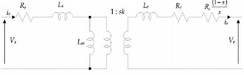
The DFIG is an induction machine with a wound rotor where the rotor and stator are both connected to electrical sources, hence the term ‘doubly-fed’. The rotor has three phase windings which are energized with three-phase currents. These rotor currents establish the rotor magnetic field. The rotor magnetic field interacts with the stator magnetic field to develop torque. The magnitude of the torque depends on the strength of the two fields (the stator field and the rotor field) and the angular displacement between the two fields. Mathematically, the torque is the vector product of the stator and rotor fields. Conceptually, the torque is developed by magnetic attraction between magnet poles of opposite polarity where, in this case, each of the rotor and stator magnetic fields establishes a pair of magnet poles, figure 2.3. Clearly, optimum torque is developed when the two vectors are normal to each other. If the stator winding is fed from a 3-phase balanced source the stator flux will have a constant magnitude and will rotate at the synchronous speed [5]. We will use the per-phase equivalent circuit of the induction machine to lay the foundations for the discussion of the torque control in the DFIG. The equivalent circuit of the induction machine is shown in figure 2.4. The stator side has two ‘parasitic’ components,
Rsand Ls, which represent the resistance of the stator phase winding and the leakage inductance
of the phase winding respectively. The leakage inductance models all the flux generated by current in the stator windings that does not cross the air-gap of the machine, it is therefore not useful for the production of torque. The stator resistance is a natural consequence of the windings being fabricated from materials that are good conductors but nonetheless have finite conductance
(hence resistance). The magnetizing branch, Lm, models the generation of useful flux in the
Figure 2.3: Magnetic pole system generated by currents in the stator and rotor windings. The stator and the rotor field generate a torque that tends to try and align poles of opposite polarity.
[image:25.612.120.520.163.287.2]In this case, of rotor experiences a clockwise torque [6]
Figure 2.4: Per-phase equivalent circuit of an induction machine
Like the stator circuit, the rotor circuit also has two parasitic elements. The rotor leakage
reactance Lr and the rotor resistance Rr. In addition, the rotor circuit models the generated
mechanical power by including an addition rotor resistance component Rr (1-s)/s. Note that the
rotor and stator circuits are linked via a transformer whose turn ratio depends on the actual turns ratio between the stator and rotor (1:k), and also the slips of the machine in an induction machine the slip is defined as :-
S =Ns−Nr
Ns (2.1)
Ns =60Fe
P rpm (2.2)
Where p is the number of pole pairs and feis the electrical frequency of the applied stator voltage,
we will first consider the operation of the machine as a standard induction motor. If the rotor circuit is left open circuit and the rotor locked (standstill), when stator excitation is applied, a
voltage will be generated at the output terminals of the rotor circuit, Vr. The frequency of this
10
synchronous speed the rotor frequency will be zero. As the rotor accelerates beyond synchronous speed (the super-synchronous mode) the frequency of the rotor voltage begins to increase again, but has the opposite phase sequence to the sub synchronous mode. Hence, the frequency of the rotor voltage is
Fr = S ∗ Fe (2.3)
No rotor currents can flow with the rotor open circuit; hence there is no torque production as there is no rotor field ψr, figure 2.5. If the rotor was short circuited externally, rotor currents can flow, and they will flow at the frequency given by equation (2.3). The rotor currents produce a rotor magnetic field, ψr, which rotates at the same mechanical speed as the stator field, ψs. The two fields interact to produce torque, figure 2.6. It is important to recognize that the rotor magnetic field and the stator magnetic field both rotate at the synchronous speed. The rotor may be turning asynchronously, but the rotor field rotates at the same speed as the stator field [5]. The mechanical torque generated by the machine is found by calculating the power absorbed (or generated) by the rotor resistance component Rr (1–s)/s. This is shown to be
Pmech= 3|ir|2(1−s
[image:26.612.137.436.392.523.2]s )Rr (2.4)
Figure 2.5: Doubly-fed induction generation system power flows [5].
[image:26.612.164.437.554.680.2]2.5. Design of High Performance Permanent-Magnet Synchronous Wind Generator
The permanent-magnet synchronous generator (PMSG), which is less noisy, high efficiency and has a long life span, has becomes one of the most important types of equipment in wind turbine systems. In 2008, Bumby designed and fabricated a 5 kW, 150 rpm axial vertical permanent-magnet (PM) generator driven directly by wind and a water turbine, where the generator uses trapezoidal shaped magnets to enhance the magnetism over conventional circular magnets. The average efficiency is 94% under no core losses and only limited eddy current loss [13].In 2011, Maia used finite element method (FEM) software to analyses the operation characteristics of an axial PM wind turbine with rated output power of 10 kW while running at the speed of 250 rpm [14]. He [15] indicated that the electromagnetic properties of the permanent-magnet machine are highly dependent on the number of slots per pole, phase, magnet shape, the stator slots and the slot opening.
[image:27.612.185.406.415.546.2]Axial flux PMSGs are widely used for vertical-axis wind turbines [18–22], however, since the axial structure magnet is placed on the inner surface of the rotor without slot and facing the stator as shown in figure 2.7., it will lengthen the distance between upper and lower magnets, which in turn requires much more magnet material and cost to improve the operational efficiency.
12
2.6. Design Dimension of the Rotor
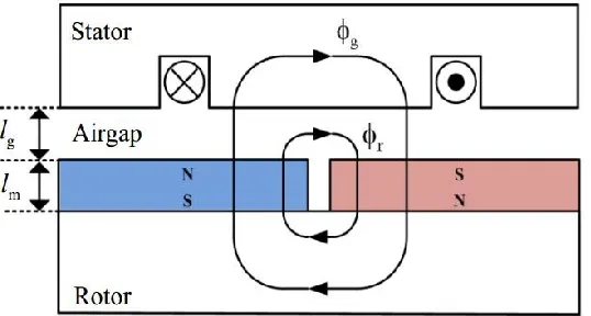
[image:28.612.120.389.255.399.2]Figure 2.8 below shows a simple and generally used surface mount with the basic geometric structure. It has a complete magnetic flux circuit, half N-pole and half S-pole, the magnetic flux travels from the rotor surface through the air gap, the magnetic silicon steel in the stator, the air gap, and then back to the rotor to form a complete closed-loop [23].
Figure 2.8: Schematic diagram of permanent-magnet synchronous generator (PMSG): Magnetic flux path [23]
[image:28.612.141.412.535.671.2]The equivalent magnetic circuit can be modeled as shown in Figure 2.9. The stator yoke width should be selected properly for reducing flux leakage and preventing magnetic saturation due to too small width of the yoke, or over weight and dimension coming from thicker yoke [24].
The air gap flux can be written as ϕg= K1· ϕ, where the leakage factor K1is typically less than
unity. For rapid analysis of the magnetic circuit, leakage magnetic reluctanceR1is ignored as
shown in figure 2b. In addition, since the steel reluctance (Rr+Rs) is small relative to the air- gap
reluctance Rg, the steel reluctance can be eliminated by introducing a reluctance factor Kr having
its value chosen to be a constant slightly greater than unity to multiply the Rg to account for the
neglected (Rr+Rs). For the machine with surface magnets under consideration, the leakage and
reluctance factors are typically in the ranges of 0.9–1.0 and 1.0–1.2, respectively, while the flux concentration factor is ideally 1.0.
The magnetic flux can be derived as [24]
ϕ = ϕr2Rm
2Rm+ 2Rg+ Rs+ Rr =
ϕr2Rm 2Rm+ 2KrRs =
ϕr 1 + KrRg
Rm
(2.5)
Since the relationship between permeance coefficient (Pc) and air gap flux density is nonlinear, doubling Pc does not double Bg. Doubling Pc, however, means doubling the magnet length, which doubles its volume and associated cost accordingly. Using the relation
Pc =lmAg
lgAm (2.6)
And
Rm= lm
µrµ0Am, Rg = lg
µ0µg, Bg = ϕg As, Br =
ϕr
Am (2.7)
Equation (2.4) becomes:
Ag = BrAm 1 + krµpr
c
(2.8)
Assuming that all the magnetic fluxes leaving the magnet through an air gap go into the stator core, then:
14
Since, as indicated above, Kr is slightly greater than unity, it is further assumed that Kr=1. Thus
substituting equation (2.9) into equation (2.8) results in:
Bg Br =
1 1 + µrllg
m
(2.10)
Determination of the air gap length lg depends on the gap magnetic flux density and the
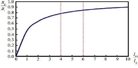
[image:30.612.176.418.391.511.2]processing of machine structure. If the air gap length is too short, it will cause serious eccentric force at high speed. Wider air gap length, however, will reduce the gap magnetic flux density and lower efficiency. The optimal ratio between magnet thickness and the air gap is usually selected in the range of 4–6 as shown in Figure 2.10. [19]. usually generator designer determines magnetic thickness in accordance with this search range. Meanwhile, production and installation tolerances must be considered to decide the eventual air gap length in order to avoid motor assembly complexity and operating problems. Equation (2.10) will be used to decide the initial air gap length.
Figure 2.10: Relationship between normalized air gap flux density and permeance coefficient. Ignoring the magnetic effects caused by the stator teeth,
The distribution of air gap flux density can be illustrated by Figure 2.11. The ratio αp-p [20]
between the width of the magnet and the pole-pitch of rotor core, written as the ratio of pole-arc
αarc to pole-pitch αpitch, is defined in Equation (11), where αarc and αpitch are the angular span of
length, will result in higher flux density. If the gap magnetic flux density waveform is closer to sinusoidal, then the induced voltage harmonics content will be smaller:
αp−p = αarc
αpitch (2.11)
When αp-p is unity, the N and S poles of the magnet are consecutive, i.e., without a gap in
between, the gap flux density is a square wave. In general, for 0 ≤ αp-p ≤ 1, Fourier series
expansion of the flux density at any electrical degree θe in the air gap can be derived as
Bg =2Bg,peak
π (x + a)n = ∑
1 − (−1)kh kh ∞
k=0
cos [kh(1 − αp−p
2 ) x1800] sinkhƟe (2.12)
[image:31.612.73.539.378.510.2]Where Bg,peak is the maximum flux density of air gap and Kh is the K-the harmonic.
Figure 2.11: Relationship between αp-p and air gap flux density: (a) αp-p = 1; (b) αp-p = 0.5
Equation (2.13) yields the k-th harmonic flux ratio
Bkh = 1 − (−1)kh
kh cos [kh(
1 − αp−p
2 ) x1800] (2.13)
It is seen from Equation (2.11) that the air gap flux density ratio of harmonic is determined by
Y-16
connected wiring. The harmonic distortion is not proportional to the phase and line voltages, but depends on the third harmonic of the phase voltage. Even if the third harmonic of the phase voltage will not appear in the line voltage, it will cause losses within each phase winding.
2.7. Optimal Sizing of Rotor Magnet
Aiming at high induced voltage and low harmonic distortion, sizing of rotor magnet will be
conducted by the best pole-arc to pole-pitch ratio αp-p fixing the internal and external diameters
of stator and rotor. Assuming open stator slot, finite element analyses using Maxwell 2-D
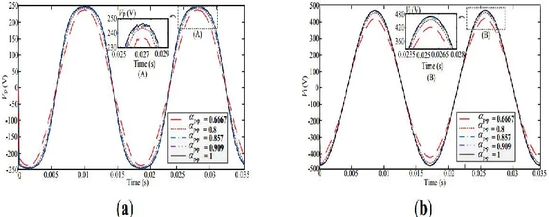
software for five different αp-p, i.e., αp-p = 0.667, 0.800, 0.857, 0.909, and 1.000 are given Figure
2.12 shows the various phase voltage Vp and line voltage Vl values obtained by Maxwell 2-D
with different αp-p. When αp-p = 0.800, the values for Vp and Vl are 243.3 V and 458.4 V,
[image:32.612.107.504.409.566.2]respectively [7].
2.8. AC Generator Construction
A main part of the alternator, obviously, consists of stator and rotor. But, unlike other machines, in most of the alternators, field exciters are rotating and the armature coil is stationary. The electrical machine, which generates AC, is known as Ac generator or alternator. The alternator may be constructed with either the armature or the field structure as revolving member as shown in figure 2.13. Small Ac generators and of low voltage ratings are commonly made with rotating armature. In such generators, the required magnetic field is produced by DC electro-magnets placed on the stationary member called the stator and the current generated is collected by means of brushes and slip-rings on the revolving member called the rotor [26].
[image:33.612.179.453.438.602.2]Practically all the large rating generators are made with revolving fields. In such generators revolving field structure or rotor has slip-rings and brushes for supply of excitation current from an outside Dc source and the stationary armature, ( also called the stator), which is made up of thin silicon steel laminations securely clamped and held in place in the steel frame, accommodates coils or windings in the slots
18
2.9. Principles of Construction
Synchronous machines come in all sizes and shapes, from the miniature permanent magnet synchronous motor in wall-clocks, to the largest steam-turbine driven generators of up to about 1500 MVA. Synchronous machines are one of two types: the stationary field or the rotating dc magnetic field. The rotating magnetic field (also known as revolving-field) synchronous machine has the field-winding wound on the rotating member (the rotor), and the armature wound on the stationary member (the stator). A dc current, creating a magnetic field that must be rotated at synchronous speed, energizes the rotating field-winding. The rotating field winding can be energized through a set of slip rings and brushes (external excitation), or from a diode-bridge mounted on the rotor (self-excited). Modern large machines typically are wound with double-layer lap windings. The rotor field is either of salient-pole as shown in figure 2.14 or non-salient-pole construction, also known as round rotor or cylindrical rotor as shown in figure 2.15. The cross section of a salient-pole synchronous machine, the rotor is magnetized by a coil wrapped around it. The figure shows a two-pole rotor. Salient-pole rotors normally have many more than two poles. When designed as a generator, large salient-pole machines are driven by water turbines. The second part of the figure shows the three-phase voltages obtained at the terminals of the generator, and the equation relates the speed of the machine, its number of poles, and the frequency of the resulting voltage.
[image:34.612.110.470.580.683.2]Schematic cross section of a synchronous machine with a cylindrical round-rotor (turbo generator) which is the typical designs for all large turbo generators. Here both the stator and rotor windings are installed in slots, distributed around the periphery of the machine. The second part shows the resulting waveforms of a pair of conductors, and that of a distributed winding. The formula giving the magneto-motive force (mmf) created by the windings.
Figure 2.15: Schematic cross section of a synchronous machine with a cylindrical round-rotor (turbo generator)
2.10. AC Generator Function
According to the Faraday's law of electromagnetic induction, whenever a conductor moves in a
magnetic field EMF gets induced across the conductor. If the close path is provided to the conductor, induced EMF causes current to flow in the circuit. The conductor coil ABCD is
placed in a magnetic field. The direction of magnetic flux will be form N pole to S pole. The coil
is connected to slip rings, and the load is connected through brushes resting on the slip rings. Consider the case 1 from above figure. The coil is rotating clockwise, in this case the direction of induced current can be given by Fleming's right hand rule, and it will be along A-B-C-D.As the coil is rotating clockwise, after half of the time period, the position of the coil will be as in second case of figure 2.16. In this case, the direction of the induced current according to Fleming's right hand rule will be along D-C-B-A. It shows that, the direction of the current changes after half of the time period, which means we get an alternating current [27].
i. Faraday’s law says: - the induced voltage in a coil is proportional to the product of the
number of loops and rate at which the magnetic field changes with the loop.
20
ii. If a coil of area A rotates with respect to a field B, and if at a particular time it is an angle
ϴ to the field, then the flux linking the coil is BAcosϴ, and the rate of change of flux is given by
dɸ
dt = BA
d(sinϴ)
dt =
dϴ
[image:36.612.151.445.208.391.2]dtcosϴ= wcosϴ(15) (2.14)
Figure 2.16: AC Generator Function
2.11. Principles of Operation of Synchronous Machines
The synchronous electrical generator (also called alternator) belongs to the family of electric rotating machines. Other members of the family are the direct current (dc) motor or generator, the induction motor or generator, and a number of derivatives of all these three. What is common to all the members of this family is that the basic physical process involved in their operation is the conversion of electromagnetic energy to mechanical energy, and vice versa. Therefore, to comprehend the physical principles governing the operation of electric rotating machines, one has to understand some rudiments of electrical and mechanical engineering [28].
established between two poles. Its intensity and direction determine the forces of attraction or repulsion existing between the two magnets.
[image:37.612.190.419.268.416.2]Figure 2.17: lines of force of opposite polarity magnets
Figure 2.18: lines of force of same polarity magnets
The direction of the lines of force is given by the “law of the screwdriver”: mentally follow the movement of a screw as it is screwed in the same direction as that of the current; the lines of force will then follow the circular direction of the head of the screw as shown in figure 2.19. The magnetic lines of force are perpendicular to the direction of current.
[image:37.612.192.412.549.681.2]22
2.12. Electricity
[image:38.612.196.401.318.446.2]Electricity is the flow of positive or negative charges. Electricity can flow in electrically conducting elements (called conductors), or it can flow as clouds of ions in space or within gases. A very useful phenomenon is that, forming the conductor into the shape of a coil can augment the intensity of the magnetic field created by the flow of current through the conductor. In this manner as shown in figure 2.23, as more turns are added to the coil, the same current produces larger and larger magnetic fields. For practical reasons all magnetic fields created by current in a machine are generated in coils. See Figure 2.20.The positive clouds are normally atoms that lost one or more electrons; the negative clouds are normally free electrons as shown in figure 2.21. The electrons flow in a conductor for example copper as shown in figure 2.20
[image:38.612.163.441.495.617.2]Figure 2.20: Magnetic field produced by the flow of electric current in a coil-shaped conductor.
Figure 2.23: The flow of electrons inside a conductor material,
2.13. PM Synchronous Machine
A direct drive wind energy systems cannot employ a conventional high speed (and low torque)
electrical machines. Hartkopfet al. in [26] has shown that the weight and size of electrical
24
2.14. Radial Flux or Axial Flux
[image:40.612.135.420.247.395.2]Air-gap orientation can be identified in two different ways. Here a hypothetical normal vector to the air-gap is adopted along the flux direction as shown in figure 2.24. The axis of the machines is assumed to be along the length of the machine in the cylindrical coordinate system. Relation of the normal vector with the axis of the machine decides the radial or axial topology. If the normal vector is perpendicular to axis, machine is called radial. If the normal vector is parallel with the axis, the machine is called axial.
Figure 2.24: Cross sectional view in radial direction and in axial direction, respectively, Of a typical radial flux PMSG [29]
2.15. Axial Flux Machines