Force Control for a 3-Finger Adaptive Robot Gripper
by using PID Controller
Amirul Syafiq Sadun1, Jamaludin Jalani2, Jumadi Abdul Sukor3, and Faizal Jamil4 Department of Electrical Engineering Technology
Faculty of Engineering Technology, Universiti Tun Hussein Onn Malaysia Batu Pahat, Johor, Malaysia
1[email protected], 2[email protected], 3[email protected], 4[email protected]
Abstract— In order to ensure that a robotic hand can successfully grasp objects without damaging them, an active compliance control can be a very useful technique to provide a safe grasping. In particular, this paper establishes a direct force control for a 3-Finger Adaptive Robot Gripper by using a PID control. A modified FSR force sensor where a plastic cover is used to ensure the contacted force during grasping can be measured and recorded. A series of grasping tests were performed to observe the performance of PID control. The experimental results show that the PID control can be a simple and reliable control scheme to provide an active compliance control through direct force control. In addition, different compliance level is feasible particularly for a stiff spongy ball.
Keywords—3-finger adaptive robot gripper; motor current; FSR force sensor; encoder position; open-loop, force control, PID Control
I. INTRODUCTION
In the earlier research, position control has been widely used over force control to produce fast, accurate and repeatable motion. Moreover, position control works best in a well-organized and controlled work space because the controlled robots operate repeatedly in the same working area. Typical examples of tasks can be found in the automation manufacturing industry such as polishing, deburring, machining and assembly. However, position control will not suffice to extend the application of the robot outside of the controlled working environment. The use of pure position control can result in fluctuation of the contact force ultimately leading to dangerous behaviors such as breakage or instability. Therefore, many compliance controls for robotic hands were introduced by researchers in order to replicate safe human grasping during the interaction. Compliance control can be defined as a measure of the ability of a manipulator to react to interaction forces [1]. One way to attain compliance control is via an active compliance control by devising a suitable interaction control strategy. Force control is the key element of active compliance control. In force control, the desired force trajectory is commanded, and force is measured in real time to realize the feedback control [1].
Examples of research on force control, particularly for the robotic hand can be found in [2]–[5]. Most of these research groups have established an active compliance control via a
specific sensor. They have developed their own robotic hands such as a DLR [6] and a Universal [7] robotic hand. Their aim is mainly to create a biomechanically realistic human hand. To allow the compliant control, a force sensor was embedded or mounted on a fingertip. This research is an attempt to perform a direct force control approach by using a PID control scheme on a 3-finger adaptive robot gripper. The application of active compliance control via direct force control for the 3-finger adaptive robot gripper will be discussed next.
II. ROBOTIQ HAND
A. General Information
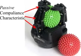
The 3-Finger Adaptive Robot Gripper as seen in Fig. 1 was developed in 2014 by the ROBOTIQ Company. In general, the hand consists 3 articulated fingers and 4 grasping modes which can adapt to a variety of sizes and shapes of the grasped objects. The 3 articulated fingers are the thumb finger (finger A), the right finger (finger B) and the left finger (finger C). Meanwhile, the 4 grasping mode include a cylindrical mode (also known as a normal mode), a spheroid mode (also known as a wide mode), a scissor mode and a pinch mode. The gripper was designed for the application of automation manufacturing and research purposes. It may also be considered the world's first industrial dexterous gripper that gives industrial robots "hand-like" capabilities. Moreover, the robot links were designed to have a passive compliance characteristic where it can automatically adapt to the shape of the object grasped and also simplifies the control movement [8].
Passive
[image:1.595.365.501.571.665.2]Compaliance Characteristic
Fig. 1. A 3-Finger Adaptive Robot Gripper by ROBOTIQ
versatility. It is certainly suitable for the application of active compliance control [9]. The external force is introduced by incorporating interlink FSR sensors on the robot finger tips. The use of the Arduino IO Package allows us to interface the Matlab/Simulink, a 3-Finger Adaptive Robot Gripper and the interlink FSR sensors. Several tests were performed to observe the grasping performance of the 3-Finger Adaptive Robot Gripper in terms of positioning and force control.
B. Grasping Mode
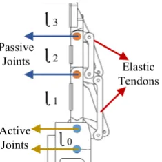
The robot supports a variety of communication protocols including Modbus RTU and Modbus TCPIP. Each finger design consists of 3 links (ɭ1, ɭ2, and ɭ3) where the active joint is
driven by a DC motor (with encoders) and the passive joint is driven by the underactuated mechanism (elastic tendons) as shown in Fig. 2[10].
Passive Joints
ɭ
2ɭ
1ɭ
3Elastic Tendons
[image:2.595.325.526.56.209.2]Active Joints
ɭ
0Fig. 2. Active and Passive Joint for 3-Finger Adaptive Robot Gripper
Moreover, the grasping force and speed can be pre-set where the robot has the capability to produce grasping force up to 60N. As mentioned earlier, there are four (4) types of grasping modes available for Robotiq hand, namely the basic grasping,wide grasping, pinch grasping and scissor grasping
(see Fig. 3). The basic mode and wide grasping are suitable for cylindrical and spherical objects. On the other hand, the pinch mode is suitable for grasping a small object (i.e precision grasping) while the scissor mode is used for tiny objects with less power consumption. However, only the normal grasping mode is utilized in this study, particularly for the experimental test.
(a) Basic Mode (b) Wide Mode
(c) Pinch mode (d) Scissor Mode
Fig. 3. Robot Grasping Modes
III. EXPERIMENTAL SETUP
A. Hardware Setup
The robot was controlled by using the Modbus RTU communication protocol in MATLAB Simulink (more specifically by using the Instrument Control Toolbox). It was connected to a computer (laptop) via USB cable. The setup also consists of Arduino UNO which represents a DAQ device in the closed loop system. The Simulink Arduino IO Package allows to communicate with the Arduino from the host where the analog input from the sensors are connected to Arduino ADC (Analog to Digital) pin. The robot and Arduino UNO were executed in the same Simulink program with two (2) different USB COM ports. Fig. 4 shows the general hardware setup for the experiment.
Force
Sensor
Adaptive Robot
3 Finger
Modbus
RTU MATLAB
SIMULINK
Arduino
UNO
Serial
USB USB
[image:2.595.107.225.249.367.2]Analog Input
Fig. 4. General Hardware Setup
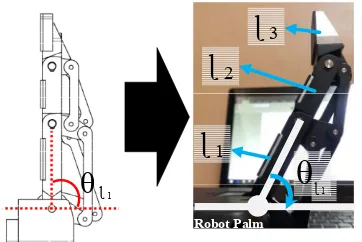
B. Joint Angular Position
In this study, the angular position for link 1 (ɭ1) is
considered during the grasping test. The desired position is based on the joint angle of link 1. Referring to Fig. 5, θɭ1is the
joint angle with reference to the robot’s palm axis. It is known that the joint angular position, θɭ1 for each robot finger is in
[image:2.595.308.554.424.549.2]Robot Palm
ɭ
2ɭ
3θ
ɭ 1ɭ
1 [image:3.595.73.254.54.175.2]θ
ɭ1Fig. 5. Robot Finger Joint Angular Position (Minimum and Maximum)
C. FSR Force Sensor Setup
In general, the FSR sensor is measured in voltage (V) which can be converted to Force (N) by using the linear model equation as presented in [11]. A suitable voltage divider circuit can also be used to convert the resistance (kΩ) to voltage (V). Although FSR sensors are simple and low cost, previous studies have shown that they are sufficient and reliable for detecting pressure [12]. In our case, obtaining a sufficient measurement from the FSR sensors can be difficult due to the insensitive contact surface. The range of response can only be achieved up to 35N or approximately 2.5V (the test requires 70N or approximately 5V). To resolve this problem, the researcher has developed a 3D printed plastic cover as seen in Fig. 6. This technique allows a proper distribution of force over the area of the contact surface. Another example of a solution can be found in [13].
Standard FSR Sensor
Contact Force
Standard FSR Sensor Plastic
[image:3.595.331.548.315.457.2]Cover
Fig. 6. 3D printed plastic cover for the FSR sensor (Dimension in mm)
The FSR sensors and the plastic covers are adhered together by using double sided tape. The sensors are then placed on each robotic finger tip as shown in Fig. 7:
FINGER A FINGER C
[image:3.595.42.294.407.526.2]FINGER B
Fig. 7. A modified FSR Sensor with a 3D Printed Plastic Cover
IV. MAHTEMATICAL MODELLING AND CONTROL STRATEGY Presenting a general model of a robot:
( ) + ( , ) + ( ) = (1)
M, V and G provide mass, velocity and gravity terms respectively. The control input represents the external force affecting each joint. In order to achieve the desired grasping of the 3-Finger Adaptive Robot Gripper, a PID controller is applied. Generally, a PID controller is written as follows:
( ) = ( ) + ( ) + (2)
where ( ) is the control output, is the proportional gain, is the integral gain, is the derivative gain and is the tracking error. The control effects completely depend on the accuracy of position controllers. Hence, the best tuning parameters of PID controller has been selected where = 0.05,
=1 and = 0.0001. Fig. 8 illustrates the block diagram for PID position control.
PID FINGER A qd
+-qA eA
PID FINGER B
+-qB eB
PID FINGER C
+-qC eC
Fig. 8. PID Position Control
A similar application by using PID control can also be found in [14], [3] and [15] for a different robotic hand. The efficiency of each finger of a 3-Finger Adaptive Robot Gripper is tested and recorded. The PID gain is manually tuned and performed in Matlab Simulink (PID controller block). The results show that all fingers produced similar performances in terms of overshoot, rise time, settling time and steady state error. Table 1 demonstrates the performance of position control for all fingers before and after tuning.
55 65 75 85 95 105 115
0 5 10 15
A
N
G
L
E (D
EG
R
E
ES
)
TIME(S)
Desired Pos Finger A Pos Finger B Pos Finger C Pos
[image:3.595.326.548.593.692.2]55 65 75 85 95 105 115
0 5 10 15
A
N
G
L
E (
D
EG
R
E
ES
)
TIME(S)
Desired Pos Finger A Pos Finger B Pos Finger C Pos
[image:4.595.48.286.63.244.2](a) After PID tuning
Fig. 9. PID Tuning Results
Table 1: Positioning Performance for all fingers Performances Rise
Time (Sec.)
Overshoot (%)
Settling Time (Sec.)
Steady State Error
(Deg.)
Before Tuning 3.3 7.4 5 1.8˚
After Tuning 3.6 0.9 3.7 0.9˚
V. COMPLIANCECONTROL
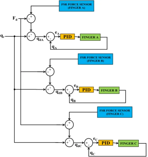
In order to maintain the desired contact force, the closed-loop system is used to introduce the force by using the interlink FSR force sensor as depicted in Fig. 6. Similar force control approach as in [16] is used and the closed loop block diagram is shown in Fig. 10. A simple proportional force control law is written as follows:
= ( − ) , ≥ 0 (3)
where is the desired contact and is a contact force (i.e. FSR sensor).
PID FINGER A
qr
+--+
+
-qA
eA Fd
FSR FORCE SENSOR (FINGER A)
qdA
PID FINGER B
+--+
+
-qB
eB
FSR FORCE SENSOR (FINGER B)
qdB
PID FINGER C
+--+
+
-qC eC
FSR FORCE SENSOR (FINGER C)
qdC
Fig. 10. Addition of Force Control Element
A. A Manual Test
In order to observe the performance of a 3-Finger Adaptive Robot Gripper (i.e. finger A, finger B, and finger C), a simple test by manually pushing each fingertip is carried out (see Fig. 11). The reference position, qr, is set to 80 degrees for all
fingers. Moreover, the desired force, Fd , is initially set to 0N
which implies no force is applied. Hence, under the condition of no force, all fingers followed the prescribed trajectory of 80 degrees successfully. The performance can be seen in Fig. 12 where the reference position, qr, and the desired position, qd (i.e.
qdA, qdB, qdC)are similar(i.e. qr = qd). However, once the force
[image:4.595.337.531.253.597.2]control is applied, a new desired position is introduced. Here, all fingers effectively follow a new trajectory as depicted in Fig. 12(a), Fig. 12(b) and Fig. 12(c) for finger A, finger B, and finger C respectively. This control strategy is known as a hybrid force-position control which can be found in [3].
Fig. 11. Exerting Force (Manually Pushed)
65 67 69 71 73 75 77 79 81
0 5 10 15 20 25 30
JO
IN
T
A
N
G
L
E
(D
E
G
R
E
ES
)
TIME (S)
Finger A Actual Position Finger A Desired Position Reference Position
65 67 69 71 73 75 77 79 81
0 5 10 15 20 25 30
JO
IN
T
A
N
G
L
E
(D
E
G
R
E
ES
)
TIME (S)
Finger A Actual Position Finger A Desired Position Reference Position
NO FORCE CONTROL
WITH FORCE CONTROL
(a) Finger A Compliance Control
[image:4.595.45.291.434.695.2]very strong (0.80 < r < 1.0). All fingers show an acceptable positive correlation (i.e. acceptable error range) for the desired and actual position. More precisely, Table 2 illustrates that the correlation strength for Finger A is moderate while Finger B and finger C are weak. One of the reasons might be due to the used of the low cost FSR sensor.
65 67 69 71 73 75 77 79 81
0 5 10 15 20 25 30
JO IN T A N G LE (D EG R EES ) TIME (S)
Finger B Actual Position Finger B Desired Position Reference Position 65 67 69 71 73 75 77 79 81
0 5 10 15 20 25 30
JO IN T A N G LE (D EG R EES ) TIME (S)
Finger B Actual Position Finger B Desired Position Reference Position
NO FORCE CONTROL
WITH FORCE CONTROL
(b) Finger B Individual Compliance Control
65 67 69 71 73 75 77 79 81
0 5 10 15 20 25 30
JO INT A N GL E (D EGR E ES ) TIME (S)
Finger C Actual Position Finger C Desired Position Reference Position 65 67 69 71 73 75 77 79 81
0 5 10 15 20 25 30
JOI N T A N GL E (D EG R E ES) TIME (S)
Finger C Actual Position Finger C Desired Position Reference Position
NO FORCE CONTROL
WITH FORCE CONTROL
(c) Finger C Individual Compliance Control Fig. 12. Individual Robot Finger Compliance Control Test
TABLEII.CORRELATION BETWEEN DESIRED POSITION AND ACTUAL
POSITION
Correlation
Coefficient, r Correlation Strength
Finger A 0.418 Moderate
Finger B 0.349 Weak
Finger C 0.320 Weak
B. Object Grasping Compliance Control
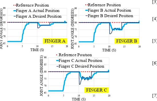
The effectiveness of the proposed compliant control is further tested on the grasped object. Here, a stiffspongy ball is used and the level of compliance is investigated (see Fig. 13). For this, two (2) different desired force where Fd = 1N and Fd = 8N are considered. The reference position, qr, is set to 80
degrees. The results of the compliant control performance are shown in Fig. 14 and Fig. 15. It is clearly seen that the ball is squashed towards the center when there is no force applied (see Fig. 13(b). When 1N desired force is applied to all fingers, the grasping positions have moved to 75 degrees for finger A, 70 degrees for finger B and 73 degrees for finger C (see Fig. 14). The actual position of all fingers follows the new grasping position satisfactorily. Similarly, the new grasping positions are satisfactorily achieved when 8N desired force is applied. The grasping positions have moved to 78 degrees for finger A, 75 degrees for finger B and 75 degrees for finger C (see Fig. 15).
[image:5.595.71.263.141.384.2](a) before (b) after Fig. 13. Grasping a Stiff Spongy Ball
65 70 75 80 85 90
0 5 10 15 20
JO IN T A N GL E (DEG R EES ) TIME (S) Reference Position Finger C Actual Position Finger C Desired Position
65 70 75 80 85 90
0 5 10 15 20
JO IN T A N GL E (DEG R EES ) TIME (S) Reference Position Finger A Actual Position Finger A Desired Position
65 70 75 80 85 90
0 5 10 15 20
JO IN T A N GL E (DEG R EES ) TIME (S) Reference Position Finger B Actual Position Finger B Desired Position
FINGER B FINGER A
[image:5.595.69.263.166.607.2]FINGER C
Fig. 14. Grasping Compliance Control at F= 1N
[image:5.595.335.545.275.358.2] [image:5.595.314.556.409.572.2]particularly for a stiff spongy ball. It is also found that the desired position, qd tends to produce a corrugated signal. The inconsistent FSR sensor readings may cause this phenomenon. Hence, a new alternative such as using better touch sensors can be good a solution to produce a good signal.
65 70 75 80 85 90
0 5 10 15 20
JO
IN
T A
N
G
L
E
(D
EG
R
E
E
S
)
TIME (S)
Reference Position Finger C Actual Position Finger C Desired Position
65 70 75 80 85 90
0 5 10 15 20
JO
IN
T A
N
G
L
E
(D
EG
REE
S
)
TIME (S)
Reference Position Finger A Actual Position Finger A Desired Position
65 70 75 80 85 90
0 5 10 15 20
JO
IN
T A
N
G
L
E
(D
EG
R
E
E
S
)
TIME (S)
Reference Position Finger B Actual Position Finger B Desired Position
FINGER B FINGER A
[image:6.595.41.315.121.298.2]FINGER C
Fig. 15. Grasping Compliance Control at F= 8N
VI. CONCLUSION
This paper presents the experimental test of position control and force control by using a PID controller for the 3-finger adaptive robot gripper. The results show that the position of the robot fingers can be satisfactorily controlled via PID control approach. In order to achieve compliance control, the low cost of FSR sensor employed. The results show that, it is sufficient to achieve compliant control via the low cost FSR sensors. However, a modified contact surface is required to enhance the performance of the FSR sensors. In this case, a “plastic cover” has been developed to allow full distribution of the contact force (i.e. enhance sensor sensitivity). Moreover, the force control has successfully been implemented on the robot fingers. The compliance level was tested manually and each finger effectively creating a different compliant level (at Fq = 1N and Fq = 8N). However, the control performance produced corrugated signal due to the use of low cost sensors (i.e. insensitive contact surface). Essentially, future study will consider more flexible and more sensitive touch sensor to improve the grasping performance of the robotic hand. Additionally, the adaptive controller scheme will be considered to provide active compliance control for the 3-Finger Adaptive Robot Grippers.
ACKNOWLEDGMENT
This topic is part of a project funded by the Fundamental Research Grant Scheme (FRGS), Vote 1480. The authors also wish to thank the Faculty of Engineering Technology, Universiti Tun Hussein Onn Malaysia for providing a platform to carry out the research activities.
REFERENCES
[1] M. Vukobratovic and B. Branislav, Dynamics and Robust Control of Robot-environment Interaction. 2009.
[2] J. Jo, S. Kim, Y. Oh, and S. Oh, “Compliance control of a position controlled robotic hand using F/T sensors,” 2011 8th Int. Conf. Ubiquitous Robot. Ambient Intell., pp. 446–450, Nov. 2011. [3] X. Wang, Y. Zhao, X. Fan, and H. Wu, “Active gripping impedance
force control with dual fingers hand,” Proc. 2011 Int. Conf. Electron. Mech. Eng. Inf. Technol. EMEIT 2011, vol. 9, pp. 4531–4534, 2011. [4] B. Y. R. V. A. N. Ham, T. G. Sugar, B. Vanderborght, K. W.
Hollander, and D. Lefeber, “Review of Actuators with Passive Adjustable Compliance/Controllable Stiffness for Robotic Applications,” no. September, pp. 81–94, 2009.
[5] J. Jalani, N. Mahyuddin, G. Herrmann, and C. Melhuish, “Active robot hand compliance using operational space and Integral Sliding Mode Control,” 2013 IEEE/ASME Int. Conf. Adv. Intell. Mechatronics, pp. 1749–1754, Jul. 2013.
[6] M. Grebenstein, A. Albu-Schaffer, T. Bahls, M. Chalon, O. Eiberger, W. Friedl, R. Gruber, S. Haddadin, U. Hagn, R. Haslinger, H. Hoppner, S. Jorg, M. Nickl, A. Nothhelfer, F. Petit, J. Reill, N. Seitz, T. Wimbock, S. Wolf, T. Wusthoff, and G. Hirzinger, “The {DLR} hand arm system,” in IEEE International Conference on Robotics and Automation (ICRA), 2011, pp. 3175–3182.
[7] W. Fukui, F. Kobayashi, F. Kojima, H. Nakamoto, T. Maeda, N. Imamura, K. Sasabe, and H. Shirasawa, “Development of multi-fingered universal robot hand with torque limiter mechanism,” in
Industrial Electronics, 2009. IECON ’09. 35th Annual Conference of IEEE, 2009, pp. 2205–2210.
[8] F. Su??rez-Ruiz, I. Galiana, Y. Tenzer, L. P. Jentoft, R. D. Howe, and M. Ferre, “Grasp mapping between a 3-finger haptic device and a robotic hand,” Lect. Notes Comput. Sci. (including Subser. Lect. Notes Artif. Intell. Lect. Notes Bioinformatics), vol. 8618, pp. 275– 283, 2014.
[9] A. S. Sadun, J. Jalani, and J. A. Sukor, “Adaptive Friction Compensation for Hand Grasping and Compliant Control,” in IEEE International Conference on Advanced Intelligent Mechatronics (AIM), 2015, 2015, pp. 0–5.
[10] M. F. Reis, A. C. Leite, and F. Lizarralde, “Modeling and Control of a Multifingered Robot Hand for Object Grasping and Manipulation Tasks,” no. Cdc, 2015.
[11] C. Lebosse, B. Bayle, M. De Mathelin, and P. Renaud, “Nonlinear modeling of low cost force sensors,” 2008 IEEE Int. Conf. Robot. Autom., pp. 3437–3442, 2008.
[12] J. a. Flórez and a. Velásquez, “Calibration of force sensing resistors (fsr) for static and dynamic applications,” 2010 IEEE ANDESCON Conf. Proceedings, ANDESCON 2010, pp. 2–7, 2010.
[13] H. E. Nabilah, M. H. Ali, K. S. Talha, N. Farahiyah, K. Wan, D. Hazry, a B. Shahriman, Z. M. Razlan, M. a Ariffin, M. Haslina, and M. Rizon, “Analysis of touching sensation based on weights of rectangular object,” Biomed. Eng. (ICoBE), 2015 2nd Int. Conf., no. March, pp. 1–6, 2015.
[14] R. L. a Shauri, N. M. Salleh, and a. K. a Hadi, “PID position control of 7-DOF three-fingered robotic hand for grasping task,” Proc. - 4th IEEE Int. Conf. Control Syst. Comput. Eng. ICCSCE 2014, no. November, pp. 70–74, 2014.
[15] M. A. A. Talib, A. S. Khamarazaman, M. Y. Salimun, J. Jaafar, and R. L. A. Shauri, “PID position control for 2-DOF robotic finger,”
Proc. - 2013 IEEE 4th Control Syst. Grad. Res. Colloquium, ICSGRC 2013, pp. 152–157, 2013.
[16] G. J. Garcia, J. A. Corrales, J. Pomares, and F. Torres, “Survey of visual and force/tactile control of robots for physical interaction in Spain,” Sensors, vol. 9, no. 12, pp. 9689–9733, 2009.