Towards building information modelling
for existing structures
Arayici, Y
http://dx.doi.org/10.1108/02630800810887108
Title Towards building information modelling for existing structures
Authors Arayici, Y
Type Article
URL This version is available at: http://usir.salford.ac.uk/id/eprint/11284/ Published Date 2008
USIR is a digital collection of the research output of the University of Salford. Where copyright permits, full text material held in the repository is made freely available online and can be read, downloaded and copied for noncommercial private study or research purposes. Please check the manuscript for any further copyright restrictions.
TOWARDS BUILDING INFORMATION MODELLING FOR
EXISTING STRUCTURES
Yusuf Arayici,
School of Built Environment, The University of Salford, UK
Abstract
The transformation of cities from the industrial age (unsustainable) to the knowledge age (sustainable) is essentially a ‘whole life cycle’ process consisting of; planning, development, operation, reuse and renewal. During this transformation, a multi-disciplinary knowledge base, created from studies and research about the built environment aspects is fundamental: historical, architectural, archeologically, environmental, social, economic, etc is critical. Although there are a growing number of applications of 3D VR modelling applications, some built environment applications such as disaster management, environmental simulations, computer aided architectural design and planning require more sophisticated models beyond 3D graphical visualization such as multifunctional, interoperable, intelligent, and multi-representational.
Advanced digital mapping technologies such as 3D laser scanner technologies can be are enablers for effective e-planning, consultation and communication of users’ views during the planning, design, construction and lifecycle process of the built environment. For example, the 3D laser scanner enables digital documentation of buildings, sites and physical objects for reconstruction and restoration. It also facilitates the creation of educational resources within the built environment, as well as the reconstruction of the built environment. These technologies can be used to drive the productivity gains by promoting a free-flow of information between departments, divisions, offices, and sites; and between themselves, their contractors and partners when the data captured via those technologies are processed and modelled into BIM (Building Information Modelling). The use of these technologies is key enablers to the creation of new approaches to the ‘Whole Life Cycle’ process within the built and human environment for the 21st century. The paper describes the research towards Building Information Modelling for existing structures via the point cloud data captured by the 3D laser scanner technology. A case study building is elaborated to demonstrate how to produce 3D CAD models and BIM models of existing structures based on designated techniques.
1
Background
Documentation and plans, in which outstanding characteristics of buildings and surroundings can be reflected, are critically important for many built environment applications such as regeneration, construction, transportation, building refurbishment, cultural heritage etc in order for adequate diagnosis and sustainable developments. However, this documentation of information currently faces a real challenge (Huber, 2002) due to extreme difficulties to obtain full documentation: Sometimes, the information in reality exists, but this fact is not known, or it is not at an acceptable quality, or not easily accessible, leading to unnecessary duplication of efforts and resources or possible loss (Fryer, 2007, Arayici, et al 2004). For example, inappropriate restorations in the historic environments can result in irreversible damages due to lack of documentation and plans. The possibility of counting upon catalogues of goods and properties and their associated meta-data, where it is possible to ascertain the possible existence of certain information and to co-ordinate actions between the organizations in charge is also a key issue (Arayici, 2007). One of the greater limitations that incur at the moment is the integration of information. It is not only important to have the data, but also its availability in digital format is critical because the greater part of the present information remains in paper format. Furthermore, these digital formats should be compatible with one another and the data should have semantic meaning and they should be inter-connected for interoperability. As a result, the usual problems of information incoherence are avoided and the duplicity of efforts in terms of personnel and economic resources is also avoided (Haist & Coors, 2005).
These circumstances shows that capturing and modelling of the real world data for various built environment applications is very challenging even though a number of techniques and technologies are now in use such as EDM (Electronic Distance Measurement), GPS (Global Positioning System), photogrammetric applications, remote sensing and building surveying applications (Fryer et al, 2007).This is because the use of these technologies has not been practical and efficient with regard to time, cost, accuracy and usefulness. In order to meet the challenges mentioned above, 3D modelling has an increasing demand by the stakeholders in the built environment field (Hakim & Beraldin, 2008). This modelling employs geospatial data captured by means of 3D digital mapping tools and technologies such as photogrammetry, 3D laser scanning. However, processing the captured data to create 3D virtual models includes a great deal of laborious work that cause very long time for delivery, high cost, low accuracy and possible distortion in the 3D models due to manual process.
would be immensely useful for a number of applications such as disaster management, regeneration, environmental simulations, computer aided architectural design (CAAD), and regional planning if a semantic 3D models of existing structures in a standard such as IFC (Benner et al 2005, Kolbe &Bacharach, 2006) are automatically produced at a reasonable cost. It will be more sophisticated model beyond 3D visualization because of being multifunctional, interoperable, intelligent, and multi-representational.
2
Real World Data Capture and Processing
In this section, 3D laser scanning is introduced for real world data capture and processing. The 3D Laser scanning technologies have been introduced in the field of surveying and are able to acquire 3D information about physical objects of various shapes and sizes in a cost and time effective way. While laser scanning based on the triangulation principle and high degrees of precision have been widely used since the 80s, `Time of Flight` instruments have only been developed for metric survey applications in this decade (Bornaz, Rinaudo, 2004). The latter has been optimized for high speed surveying, and a set of mechanisms that allows the laser beam to be directed in space in a range that varies according to the instrument that is being used. For each acquired point, a distance is measured on a known direction: X, Y, and Z coordinates of a point can be computed for each recorded distance direction. Laser scanners allow millions of points to be recorded in a few minutes. Because of their practicality and versatility, these kinds of instruments have the potential to be widely used in the field of architectural, archaeological and environmental surveying (Valanis & Tsakiri, 2004). Research studies have been undertaken to investigate the advantages of 3D laser scanning technology over the current technologies available for natural environment, cultural heritage documentation, mining, and tunnel bridge construction and as built survey for defect detection. In addition, 3D prototyping in manufacturing has been carried out for small objects such as car seats. However, the same concept has not been applied in the built environment effectively.
produce 3D models of the scanned objects. This is required to convert the point cloud data into simpler forms that can be manipulated by other built environment software systems such as CAD because the point cloud data occupies huge disk space and requires very high spec computers (Arayici, et al 2004, Litchi, 2005).
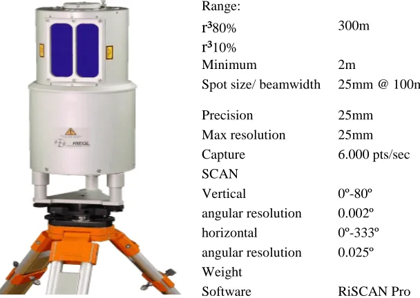
For the case study project, a Riegl LMS-Z210 3D laser scanner used in combination with PolyWorks software point data. The LMS-Z210 3D imaging sensor is a rugged and fully portable sensor for the rapid acquisition of high-quality three-dimensional images even under highly demanding environmental conditions. The scanner provides a combination of wide field-of-view, high accuracy, and fast data acquisition. The scanner is connected to a 12V battery and a ruggedised lapt
Range:
r³80% 300m
r³10%
Minimum 2m
Spot size/ beamwidth 25mm @ 100m Precision 25mm
Max resolution 25mm Capture 6.000 pts/sec SCAN
Vertical 0º-80º angular resolution 0.002º horizontal 0º-333º angular resolution 0.025º Weight
[image:5.612.150.454.283.499.2]Software RiSCAN Pro Table 1: Specification of LMS Z210 scanner used in the case study area
3
Building Information Modelling
all objects in it have properties and relationships and this information can be for data mining to develop simulations or calculations using the model data (Ballesty, 2007).
The principal difference between BIM and 2D CAD is that the latter describes a building by 2D drawings such as plans, sections, and elevations. Editing one of these views requires that all other views must be checked an updated, an error-prone process that is one of the major causes of poor documentation today. In addition, the data in these 2D drawings are graphical entities only such as lines, arcs and circles, in contrast to the intelligent contextual semantic of BIM models, elements and systems such as spaces, walls, beams and piles (Ballesty, 2007). The generic attributes of BIM are listed below:
• Robust geometry: objects are described by faithful and accurate geometry that is
measurable.
• Comprehensive and extensible object properties that expand the meaning of the
object. Objects in the model either have some predefined properties or the IFC specification allows for the assignment of any number of user or project specific properties are richly described with items such as a manufacturer’s product code or cost or date of last service.
• Semantic richness: the model provides for many types of relationships that can be accessed for analysis and simulation.
• Integrated information: the model holds all information in a single repository
ensuring consistency accuracy and accessibility of data.
• Lifecycle support: the model definition supports data over the complete facility
lifecycle from conception to demolition, for example, client requirements data such as room areas or environmental performance can be compared with as designed, as built or as performing data
The key benefits of BIM is its accurate geometrical representation of the parts of a building in an integrated data environment are listed below (Ballesty, 2007)
• Faster and more effective processes - information is more easily shared can be value added and reused.
• Better design – building proposals can be rigorously analysed, simulations can be performed quickly and performance benchmarked, enabling improved and innovative solutions
• Controlled whole life costs and environmental data – environmental performance is more predictable, lifecycle costs are understood.
• Better production quality - documentation output is flexible and exploits
automation.
• Automated assembly – digital product data can be exploited in downstream
• Better customer service – proposals are understood through accurate visualisation • Lifecycle data – requirements, design, construction and operational information can
be used for, for example, facilities management.
• Integration of planning and implementation processes – government, industry, and manufacturers have a common data protocol
• Ultimately, a more effective and competitive industry and long term sustainable
regeneration projects
Interoperability is defined as the seamless sharing of building data between multiple applications over any or all applications (or disciplines) over any or all lifecycle phases of a building’s development. Although BIM may be considered as an independent concept, in practice, the business benefits of BIM are dependent on the shared utilisation and value added creation of integrated model data.
To access the model data therefore requires an information protocol, and although several vendors have their own proprietary database formats, the only open global standard are IFC (Industry Foundation Classes) that published by the international Alliance for interoperability (IAI) and cityGML (city Geographic Markup Language) that is published by the Open Geospatial Consortium. However, IFC standard is explained only as the focus of information modelling in this paper is towards IFC
3.1 IFC (Industry Foundation Classes)
The scope of the IFCs includes product information: it models the physical parts that make up a building, including the semantic identification of all the building’s systems and elements, their geometry, design properties, etc. Within the IFC’s, the representation of certain building systems (e.g., basic architectural features such as walls, doors, floors, etc.) is fairly extensive while other building systems (e.g., electrical systems) have received very little development to date (IFC release 2X2, currently in development at the time of writing, will extend many of these areas). The scope also includes non-product information, such as costs, schedules, people and organizations, resources, documents, etc. The largest effort to date in implementing IFCs has been in the area of product information, such as building geometry. Many of the IFC-compatible systems that have been developed to date do work with non-product information. However, in almost all cases, these systems use product information as an input to non-product applications. For example, the product model is used to input geometry into an energy simulation application, or to input a quantity takeoff into an estimating application. Very few systems have written non-product information back into IFC files and used these to exchange non-product data.
4
A Case Study Approach for Real World Data Modeling
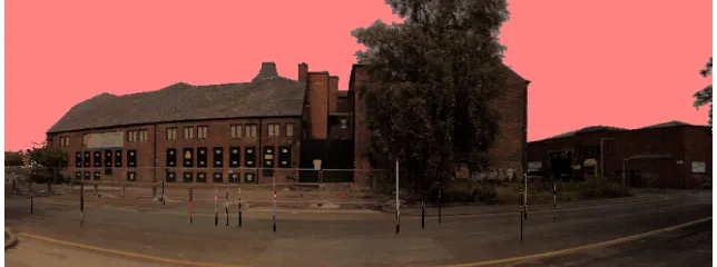
The case study building under refurbishment is selected in East Manchester. The paper explains the point cloud data capture, processing and modelling. A true colour image generated from scanned data shown in figure 1 and 2. 3D point cloud data was captured with the Riegl LMS Z210 scanner together with the companion software called RiSCANPro. There were 12 scan positions outside the building. The individual scans were conducted at two phases. In the first phase, an overview scan was done. The overview scan is quick scan with rough resolution and with 330 degree horizontal field of view. At the second phase, much higher quality of scan was done. To do this, initially a frame of interested area, which was the building in the field of view, in the previous coarse scan on laptop, was defined. Following this, scanning resolution was set to 13mm. therefore; the second phase scan operation took longer time at around 9-10 minutes as opposed to initial overview scan, which took only 15 seconds
Figure 2: rear point cloud image of the building based on the scanner field of view
[image:9.612.145.467.102.222.2]For scans registration and post processing, RiSCANPro and the Polyworks software were used consecutively based on project requirements and scanning strategy. Once all the scans are registered, a point cloud model of the scanned object is obtained. A 3D mesh model can be generated using the IMMerge Module of Polyworks software. Meshing parameters such as surface sampling step, reduction tolerance, smoothing and maximum distance, are important to create smooth and filtered high quality mesh model with high resolution. To achieve this, it is important to take into account the scanning parameters. The accuracy and resolution of the model will be dependent on the scanning resolution and the laser scanner accuracy. The output from IMMerge is a polygonal mesh model of the building. The final merged model can then be exported from IMMerge and imported into IMEdit for refining. Figure 3 shows an image of the mesh model of the case study building in the IMEdit module.
Figure 3: The Jactin house mesh model in IMEdit of Polywork
the model could be oblique in space. As a result, width, height and length of the model can be viewed horizontally and vertically when the model is viewed from X, Y or Z perspectives of the coordinate system. For example, the script below can automatically align the model XZ coordinate dimensions. In the same manner, the model can be aligned with XY and YZ coordinate dimensions.
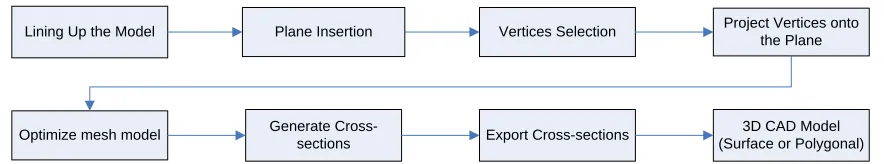
Lining Up the Model Plane Insertion Vertices Selection Project Vertices onto
the Plane
Optimize mesh model Generate
Cross-sections Export Cross-sections
[image:10.612.89.531.183.265.2]3D CAD Model (Surface or Polygonal)
Figure 4: Point Cloud Data editing and CAD extraction process
The script below is to align a mesh model in XZ plane
version "4.0" #VIEW POSE Y_POS VIEW POSE Y_NEG
TREEVIEW MODEL VIEW DEFAULT_STATIC COLOR VERTEX_COLOR EDIT PLANE CREATE XZ_PLANE
SELECT ELEMENTS
EDIT PLANE CREATE FROM_3_VERTICES TREEVIEW SELECT NONE
TREEVIEW MODEL SELECT ( 1, "On" ) DECLARE I
DECLARE J
DECLARE MYPLANEONE DECLARE MYPLANETWO
TREEVIEW PRIMITIVE PLANE GET_NB (I) set j expr($i-1)
TREEVIEW PRIMITIVE PLANE NAME GET ($I, MYPLANEONE) TREEVIEW PRIMITIVE PLANE NAME GET ($J, MYPLANETWO) ECHO ("$MYPLANEONE")
ECHO ("$MYPLANETWO")
TREEVIEW PRIMITIVE PLANE SELECT ( $I, "On" ) #TREEVIEW PRIMITIVE PLANE SELECT ( $J, "On" )
ALIGN ROTATE_PLANE_A_TO_PLANE_B ( $MYPLANEONE, $MYPLANETWO ) TREEVIEW SELECT NONE
TREEVIEW PRIMITIVE PLANE SELECT ( $J, "On" ) TREEVIEW PRIMITIVE PLANE SELECT ( $I, "On" ) VIEW VISIBILITY OBJECTS HIDE ( )
Figure 5: Code for model lining up
According to the script in figure 6, all the vertices that are 4.5 cm away from the plane are automatically selected and projected on the plane. However, this can vary from cm level to mm level depending on the scan resolution and accuracy of vertex positions. Following the projection of vertices, it is necessary to optimize the mesh model to make the model consistent and if necessary reduce the number of points at some regions in the model to reduce the file size and avoid point intensity and heterogenic point scatter. Mesh optimization may be applied to a selection, or to the entire model. There are a number of parameters that need to be adjusted for mesh optimization. These are (i) sensitivity, (ii) minimum number of triangles per vertex, (iii) max number of triangles per vertex, (iv) min inner angle, (v) max dihedral angle. After mesh optimization, the triangulated mesh is more consistent, and the surface curvature is better described. Mesh optimization works best if the polygonal mesh is relatively smooth.
version "4.0"
#CAD LINES EXTRACTION FROM POLYGONAL MESH MODEL EDIT PLANE CREATE PARALLEL_TO_PLANE
#TREEVIEW PRIMITIVE PLANE SELECT ( $I, "On" ) DECLARE I
TREEVIEW PRIMITIVE PLANE GET_NB (I)
#TREEVIEW PRIMITIVE PLANE GET_NB_SELECTED (I) #WHILE $I<$I+1
# ++I #ENDWHILE
TREEVIEW PRIMITIVE PLANE SELECT NONE TREEVIEW PRIMITIVE PLANE SELECT ($I, "On" ) VIEW VISIBILITY OBJECTS HIDE ( )
SELECT VERTICES USING_PLANES ABOVE_AND_BELOW ( 4.5e-002, "Off" ) EDIT VERTICES PROJECT ONTO_PLANE
#EDIT CROSS_SECTION CREATE FROM_PLANE_SELECTION ( 0.0 ) SELECT ELEMENTS
Figure 6: Code Plane insertion, vertex selection and projection onto the plane
Figure 7: front view of Jactin House CAD model produced from point cloud data
Figure 8:rear view of the building from an oblique angle as CAD model
4.1. Transfer to BIM
The object-oriented CAD modelling approach utilises the Microstation Triforma software, which employs the building information modelling concept. All information about a building (or at least as much as possible) is recorded in a 3 dimensional model. Traditionally a given door in a building would be drawn in at least three or four places (plan, building elevation, building section, interior elevation, etc). In the Triforma building information modelling, it is constructed once and these various drawings are later extracted automatically. It requires building objects that are defined, edited and stored in the triforma library.
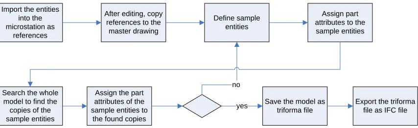
[image:12.612.93.517.258.424.2]whole process can be fully automated for OO CAD modelling for the entire process in figure 9.
Import the entities into the microstation as
references
After editing, copy references to the master drawing
Define sample entities
Assign part attributes to the sample entities
Search the whole model to find the copies of the sample entities
Assign the part attributes of the sample entities to
the found copies
Save the model as triforma file
Export the triforma file as IFC file yes
no
Figure 9: experimented Object Oriented CAD modelling
In computer vision, some research activities have been undertaken for shape representation and semantic retrieval from images [9]. By means of a search engine, to semantically annotate a shape library can be challenging for complex shapes and structures. However, if the shapes are the CAD graphics as illustrated in figure 7 and 8, it is possible to annotate it automatically. There are efficient techniques available in the literature. However, a simple way is to design some templates representing each type of objects, and then mapping those new shapes into templates. When a library of annotated objects is evolved over time, this library can be used to pattern match new shapes from the CAD graphics, which is derived from point cloud data.
The complexity of annotation depends on how large shapes are and the nature of these shapes. For example, if it is a new project, which is not large, newly created objects can be manually annotated and stored into the library, so that the annotated and stored objects may be reused in the same project or other projects. That is, whenever an object is necessary later in a project, it can be simply found in the library and manipulated for new circumstances and scenarios. If a required object cannot be found in the library, it can be created and annotated manually for the first time and then stored into the library in order to enrich the library. However, in case of a large amount of objects to be defined and annotated, which also need to be stored into the library, these objects can be defined with some pattern recognition techniques such as the contour based shape descriptors, like elongation, compactness, Fourier descriptors etc, normally those descriptors are size, translation and rotation invariant (Zhan & Lu, 2004 ).
approximate pattern matching will include a threshold tolerance for matching the pattern sought.
As a result of the matching strategy outlined above, the pattern recognition can be worked out for the 3D CAD models of buildings. Attributes of the objects matched in the library will be assigned to the building entities in the CAD model. Subsequently, this will lead to transforming the 3D CAD model into Triforma based BIM model. Once this transformation is completed, the Triforma based BIM model can be mapped into IFC schema to save the model in IFC data model by means of the IFC plug-in of Triforma. The image in figure 10 shows the IFC model of the Jactin house in the Microstation triforma environment that has IFC 2X plug-in installed.
Figure 10, IFC model of the Case Study building in Microstation Triforma
5
Conclusion
The research is ongoing and the experience is aimed to expand to apply into various buildings including historical buildings that have intensive architectural details.
Therefore, the spin images generation (Huber, 2002), (Johnson 1997), Hough
transformation and candy edge detection (Luhmann, et al, 2006) are being investigated to be embedded into the algorithm.
comprehensive and sophisticated simulation platforms to utilize when needed by the built environment applications in order to achieve long term sustainable built environment for living and working in the knowledge age.
6. References
Arayici, Y., (2007), “An Approach for Real World Data Modeling with the 3D Terrestrial Laser Scanner for Built Environment”, Journal of Automation in Construction, Vol 16, Issue 6, pp 816-829, Sep. 2007.
Arayici, Y., Hamilton, A., Gamito, P., Albergaria, G., (2004) “The Scope in the INTELCITIES Project for the Use of the 3D Laser Scanner”, in the Proceeding of ECT2004: The Fourth International Conference on Engineering Computational Technology, 7-9 September 2004, Lisbon, Portugal. ISBN 0948749962 pp 111-112.
Ballesty S, (2007), “Building Information Modelling for Facilities Management”, project report by Co-operative Research Centre (CRC) for Construction Innovation, Queensland, Australia 2-6
Benner, J., Greiger A., Leinemann, K., (2005), “Flexible Generation of Semantic 3D Building Models”, in the Proceeding of the 1st International Workshop On Next Generation 3D City Models, Bonn 2005.
BLIS, 2002. “BLIS home page”, web page at
Bornaz L., Rinaudo F., 2004, Terrestrial Laser Scanning Data Processing, XXth ISPRS Congress, 12-23 July 2004 Istanbul, Turkey, Commission 5, pp514-520.
Falquet G., Metral C., (2005), “Integrating Urban Knowledge Into 3D City Models”, in the Proceeding of the 1st International Workshop On Next Generation 3D City Models, Bonn 2005.
Froese T (2003)
Issue
Fryer J., Mitchell H., Chandler J. (2007), “Applications of 3D Measurements from Images”, Whittles Publishing
Hakim S. and Beraldin J. (2007), “Sensor Integration and Visualisation” book chapter in Applications of 3D Measurement from Images, (Eds. Fryer J.G., Mitchell, H.L., Chandler, J.H.), Whittles publishing
Huber F.D. “Automatic Three dimensional Modelling from Reality” PhD thesis in Robotics, The Robotics Institute of Carnegie Mellon University, Pittsburgh, Pennsylvania 15213, July 2002, CMU-RI-02-35
Huber F.D. “Automatic Three dimensional Modelling from Reality” PhD thesis in Robotics, The Robotics Institute of Carnegie Mellon University, Pittsburgh, Pennsylvania 15213, July 2002, CMU-RI-02-35
International Alliance for Interoperability
Johnson, A., (1997), “Spin Images: A representation for 3D Surface Matching”, CMU-RI-TR-97-47, Carnegie Mellon University, Pittsburgh, Pennsylvania 15213, August 13th, 1997
Kolbe, T., Bacharach S., (2006), “CityGML: An Open Standard for 3D City Models” Directions Magazine by The Worldwide Source for Geospatial Technology, July 03,
Lichti, D., 2004, “A Resolution Measure For Terrestrial Laser Scanners”, XXth ISPRS Congress, 12-23 July 2004 Istanbul, Turkey, pp216-222.
Luhmann, T., Robson, S., Kyle, S., Harley, I., (2006), “Close Range Photogrammetry, Principles, Methods and Applications”, Whittles Publishing, ISBN 1-870325-50-8
Nebiker, S., Schutz S., Wust T., (2005), “A Model Driven Geospatial Content Management Framework with Support for 3D City Models”, in the Proceeding of the 1st International Workshop On Next Generation 3D City Models, Bonn 2005,
Thiemann F., Sester M., (2005), “Interpretation of Building Parts from Boundary Representation”, in the Proceeding of the 1st International Workshop On Next Generation 3D City Models, Bonn 2005.

![Synthesis of 3 methoxy 2 (1,3,4 oxadiazolyl,1,3,4 thiadiazolyl and 1,2,4 triazolyl)naphtho[2,1 b]furans of biological interest](data:image/gif;base64,R0lGODlhAQABAIAAAP///wAAACH5BAEAAAAALAAAAAABAAEAAAICRAEAOw==)