Journal of Chemical and Pharmaceutical Research, 2014, 6(7):2150-2154
Research Article
CODEN(USA) : JCPRC5
ISSN : 0975-7384
The research of a new charging control method to reduce the power
grid harmonic
Maofa Gong, Ningxia Yang and Xiaofei Wang
College of Electrical Engineering and Automation, Shandong University of Science and Technology, Qingdao, China
__________________________________________________________________________________________
ABSTRACT
The paper comes up a kind of charging control method about Multi-objective search algorithm based on PSO charging control strategy which can reduce the harmonic content and power load of charging at noon to reduce the impact of the actual bus charging station running bringing to the power grid harmonic and power load. The simulation is carried on according to the charging station actual operation from the angle of harmonic suppression and power load balance by constructing the model analysis of charging stations harmonic characteristic. The simulation shows that the charge under this kind of charging control strategy can reduce the harmonic content effectively and cut down the peak load availably.
Keywords: Charging station; power grid harmonic; Charging control method; PSO
_____________________________________________________________________________________________
INTRODUCTION
With the development of science and technology, petroleum resources, the deterioration of environment, development of environmental protection and energy saving green transport has become an important problem the car industry [1]. Electric vehicles have the double advantages of energy-saving and environmental protection as new energy vehicles. Oil is to alleviate the crisis, beautify the urban environment necessary to choose. Electric cars replace fuel electricity and reduce the urban vehicle exhaust emissions, energy sources. Cooperating with the use of the other new energy like clean energy such as wind, solar, geothermal energy, the effect is good. Therefore, the use of new energy is the important way to solve the problem of energy shortage and environmental problems.
EXPERIMENTAL SECTION
Electric vehicle control problem is a nonlinear, high dimension, multivariable, constraint optimization problem. The general linear optimization algorithm is difficult to solve such problems. This paper uses particle swarm objective (PSO) search algorithm. Particle swarm optimization algorithm (PSO) has simple process, fast convergence rate and is easy to implement. It is not only can effectively solve the single objective optimization problem but also solve multi-objective optimization problems which have the very good effect.
In this algorithm, the speed of the particle of ith of vi and their locations xi expression formula is:
1 1 ()( [ ] 1) 2 ()( [ ] 1)
i i i i
v =v− w+C R and pB est i − x− +C rand gB est i − x−
(1)
i i
i
x
v
x
=
−1+
(2)In Type, i is the number of iterative update, w as the inertia weight, xi is the first iteration update particle space
position, vi is the i th
particle iteration speed, the Rand ()and the rand () is a constant between interval [0, 1], C1 and C2 respectively is learning factor and constant.
The working principle of the electric car charger is that three-phase power grid transform alternating current to direct current through the rectifier device. Then a high frequency power conversion circuit and filter circuit output charge to battery[5-7]. The general structure diagram is shown in figure 1.
f
R Lf
f C ) ( 0 0 P I
Fig.1 charger structure diagram
Power battery charging time is for up to four and a half hours, while the charger is changing the output voltage and current, but can be thought of in a very small time constant output voltage and current of the charging machine, the output power is constant, so the available a resistor in a short period of time to simulate the input impedance of power conversion circuit. The entire charging process can use a nonlinear resistor to wait instead of power conversion circuit impedance. So it can use a resistor in a short period of time to simulate the input impedance of the power conversion circuit and the charging process of a nonlinear resistor can be used in place of the power conversion circuit impedance.
O O I O I I I I I
I
U
U
P
U
P
U
I
U
R
×
×
=
×
=
=
=
2η
2η
2(3)
Charger power output curve through data collection and battery charging process, using curve fitting.
≤
<
≤
<
=
− × −270
150
,
150
0
,
79
.
0
)
(
) 150 ( 021 . 0 max 048 . 0 maxt
e
P
t
t
P
t
P
t o o o (4)The bus charging station is basically charging twice for bus during the day. Time: 11:00-13:00. 20:00-1:00. The two hours during the day is a supplementary power stage, and during this time each vehicle access for very short intervals, which prevent the bus station avoid the peak harmonic content and peak power load at noon.
))
(
sin(
)
(
2
sin
)
(
cos
)
(
)
(
)
(
1 Im 1 O m m O O bm m O am O aP
f
t
m
P
f
t
m
P
f
t
m
P
f
P
f
t
i
ϕω
ω
ω
+
=
+
=
=
∑
∑
∞ = ∞ = (5)In type:
2
/
))
(
)
(
(
)
(
2 2Im
P
Of
amP
Of
bmP
Of
=
+
f
ϕm(
P
O)
=
f
am(
P
O)
/
f
bm(
P
O)
m
=
6
k
±
1
(
k
=
0
,
1
,
2
,
L
,
m
>
0
)
The charging station harmonic superposition rule related with power charger when the charger power is the same. Each harmonic superposition RMS will increase exponentially and when the charger is not the same power output and each harmonic superposition RMS, phase angle are changed, the offset phenomenon occurred.
There is often a certain amount of remaining after the day’s work, remaining charge too much as increasing the charging load day supplement power stage. The reduction of the remaining SOC can be used to reduce the harmonic content and the load.
RESULTS AND DISCUSSION
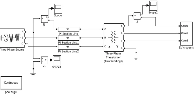
Bus station simulation model is established including three phase power supply, transmission line, transformer and charging machine. 10 kV power utility grid by 5 Km transmission line due to the actual power grid. The length of the transmission lines can produce certain influence to analysis in this paper. This article uses a PI type circuit to simulate the actual transmission lines. Simulation model select the type distribution transformer adopts Dyn11 connection mode to make 3 times and 3 integer harmonics in the transformer high voltage side of the triangle formed in the winding circulation, prevent charging stations within the part of the higher harmonic injected into power grid.Its equivalent simulation model is shown in figure 2.
Continuous pow ergui i + -i2 i + -i1 v + -V1 A B C Three-Phase Source A B C a b c n Three-Phase Transformer (Two Windings) Scope2 Scope1 Scope
Pi Section Line2 Pi Section Line1 Pi Section Line
Conn1 Conn2 Conn3
[image:3.595.141.477.438.608.2]EV chargers
Fig. 2 charging station simulation model
The charger for the simulation parameters is: L=1.5mH, C=2000µF,ŋ=94%.Research on the effects of charging
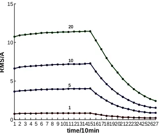
1 2 3 4 5 6 7 8 9 101112131415161718192021222324252627 0
5 10 15
1
R
M
S
/A
time/10min
5 10 20
1 5 10 20
Figure 3 different sets of 5 harmonic change curve
From the figure 3, We can see that the entire charging process harmonic current decreases after increasing first peaked at 150 min and the harmonic maximum points to judge whether the harmonic content standards and determine the harmonic control scheme plays an important role. The harmonic RMS increase gradually with the increase of the number of charger but the harmonic current RMS is not multiply but a certain degree of offset each other.
[image:4.595.223.384.79.216.2]Assuming the same charger other parameters, only the output power is different. The 9 kw power, 25 kw, 45 kw charger and 60 kw charger which is used respectively with two 60 kw charger do comparison and analysis at the same time. The simulation is used under maximum power charger. Simulation can get harmonic content such as table 1,2.
Table 1 10kv side RMS harmonic current injection
Power chargerⅠ/Ⅱ
Harmonic frequency and harmonic current RMS(A)
5 7
60kw/60kw 1.65 0.83
60kw/45kw 1.48 0.74
60kw/25kw 1.23 0.6
60kw/15kw 1.11 0.53
60kw/9kw 1.04 0.35
Table 1 0.4kv side RMS harmonic current injection
Power chargerⅠ/Ⅱ
Harmonic frequency and harmonic current RMS(A)
5 7 11 13 17 19
60kw/60kw 43.59 22 15.38 11.02 8.16 6.48 60kw/45kw 38.83 19.3 13.68 9.76 7.41 5.88 60kw/25kw 32.46 15.74 11.33 7.95 6.3 4.95 60kw/15kw 29.26 14.06 10.15 7.09 5.73 4.49 60kw/9kw 27.31 13.04 9.36 6.46 5.3 4.1
The table shows that every harmonic current RMS with the increase of charger power is different.
CONCLUSION
This article comes up with a kind of charging control method about Multi-objective search algorithm based on PSO charging control strategy through the charging station built imitation summarized the basic characteristic of the charging station harmonic, and basic features of harmonic analysis. Verification results show that the scheme can effectively reduce the harmonic content and can reduce the load.
Acknowledgements
[image:4.595.171.443.392.502.2][3] BH Wang; HJ Huang; XL Wang, Neural Computing and Applications, 2013, 22: 21-28. [4] WL Zhang; B Wu ; WF Li, et al, Power System Technology, 2009, 33(4): 1-5.
[5 ]YX Lu; XM Zhang ; XW Pu , Proceedings of the CSU-EPSA, 2006, 18(3): 51-54.