© 2016, IRJET | Impact Factor value: 4.45 | ISO 9001:2008 Certified Journal
| Page 2113
A Comparative Survey On Harmonic Optimization Of Multilevel
Inverter
Tikeshwar Gajpal
1, Nivedita Hedau
21
Dept. of Electronics and Telecommunication Engineering, Raipur Institute of Technology, C.G., India
2Dept. of Electronics and Telecommunication Engineering, Raipur Institute of Technology, C.G., India
---***---Abstract -
Multilevel Inverters have many advantagesconsisting of low cost, right performance and a few application which include PV panels and gas cells. Cascaded H-bridge MLI is one kind of these MLIs. Unlike the traditional inverter, the MLI's output voltage has a reduced THD with higher harmonic profile. Mathematical techniques for harmonic elimination are offered in some of the literatures however solving a non-linear transcendental equation set describing the SHE problem using these methods are not suitable for multi level inverters. A hybrid optimization set of rules to locate the most reliable switching angles in a Multilevel Inverter (MLI) is proposed in this paper. The switching angles are optimized to reduce low frequency harmonics. Total Harmonic Distortion (THD) method are implemented in order to lessen the switching losses. This paper summarizes different hybrid optimization techniques, which included the mechanisms of particle swarm optimization (PSO), genetic algorithm (GA), fuzzy logic controller and biography based algorithm which will optimize parameters. A comparative study of different algorithm has been studied.
Key Words
:
cascaded multilevel inverter, particle swarm optimization (PSO), genetic algorithm (GA), step modulation, multiple carrier sine pulse width modulation.
1. INTRODUCTION
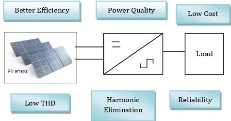
In recent decades, the studies on Multilevel Inverters (MLI) were increasing as it turns into a viable answer for high power applications, along with HIGH motor drives, railway traction programs, high-voltage DC transmissions (HVDC), STATCOM and static VAR compensators. An advantage of MLIs is that their switching frequency is lower than traditional inverters meaning the switching losses are reduced. These MLIs has increased the output voltage and brought a way to limitation of classical semiconductor switches. Fig.1 illustrate some of advantage of the H-bridge MLI. The technology of MLIs is
[image:1.595.331.569.390.515.2]based totally on production special DC voltage levels composition of these stages to acquire higher output voltage waveform. The output voltage waveform by means of including step has lower total harmonic distortion (THD) and reduced the harmonics in contrast to square wave inverters [1]. In excessive power Systems, Multilevel Inverters can appropriately replace the existing system that uses conventional multi-pulse converters without the need of the transformers.
Fig -1:
Some of advantages of H-bridge MLI
All the three multi-level inverter topologies (diode clamped, flying capacitors, and cascaded multi level inverter) can be used in reactive power compensation without having the voltage unbalance problem. But the Cascaded multi level inverter uses simple H-Bridge configurations which are connected in series, utilizes fuel cells, solar cells & biomass energy as DC sources. Multilevel seeks to synthesize a waveform much more similar to a sinusoidal signal, which, relying on the DC number of resources available, the distortion might be decrease. Among its important advantages we are able to highlight:
The arrangement of the input voltage into multiple stages can increase several times the voltage converter work using the identical switches in a conventional converter.
Load
Better Efficiency Power Quality Low Cost
Low THD Harmonic
Elimination
© 2016, IRJET | Impact Factor value: 4.45 | ISO 9001:2008 Certified Journal
| Page 2114
Power converters increases to use better voltages, without increasing current, therefore avoiding further losses and therefore improve performance of Converter.
1.1 CASCADED H-BRIDGE
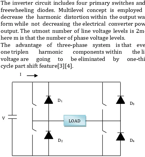
A Cascaded bridge inverter is known as an H-bridge cell. The inverter circuit includes four primary switches and 4 freewheeling diodes. Multilevel concept is employed to decrease the harmonic distortion within the output wave form while not decreasing the electrical converter power output. The utmost number of line voltage levels is 2m-1, here m is that the number of phase voltage levels.
[image:2.595.35.277.216.479.2]The advantage of three-phase system is that every one triplen harmonic components within the line voltage are going to be eliminated by one-third cycle part shift feature[3][4].
Fig -2: Cascaded H-Bridge Inverter
One of the benefits of those inverters is that it wants less variety of parts in comparison to two different sorts; therefore it will be economically preferable. Furthermore the modularity and simply long structure square measure different profitable characteristics of this kind of inverters. The output voltage that is made by series affiliation of separate H-bridges, is that the add of the values of separate DC sources, which can be obtained from batteries, star cells or ultra-capacitors. Fig. one demonstrates a cycle of seven level stepwise voltages as a typical output of the 3 level electrical converters.
2. HARMONICS
In power quality elements are the harmonic contents within the electrical system. Normally, harmonics may be divided into two types: 1) voltage harmonics, 2) current harmonics. Current harmonic are typically generated by harmonics contained in voltage supply and depends on the type of the load along with resistive load, capacitive load,
and inductive load. Load harmonics can cause the overheating of the magnetic cores of transformer and vehicles [2]. On the other hand, source harmonics are especially generated by power supply with non sinusoidal voltage and non-sinusoidal current waveforms. The frequency of each harmonic component is a multiple of its fundamental frequency. For the purpose of a steady state waveform with equal positive and negative half cycles [3], the Fourier series can be expressed as follows:
F(t) =
∑
(1)
There are several methods to indicate the quantity of harmonics contents. The most widely used measure is the total harmonics distortion (THD), which is defined in terms of the magnitudes of harmonics:
THD
√
(
2)
is the magnitude of the nth harmonic as a percentage of the individual distortion.
2.1 HARMONIC ELIMINATION
The multilevel fundamental switching scheme inherently affords the opportunity to do away with certain lower order harmonics by means of various instances at which positive switches are became ON and became OFF (i.e. varying the switching angles).here 5th ,7th ,11th and 13th
harmonics are minimized.
2.2 SELECTIVE HARMONIC ELIMINATION
(SHE)
There are unit completely different management techniques applied to regulate the output voltage wave in structure inverters. The classification of those management techniques area unit essentially primarily based on the change frequency. There are two techniques, which are unit a) low (fundamental) switching frequency techniques, and b) high change frequency techniques. The house Vector management (SVC) and Selective Harmonic Elimination (SHE) area unit thought-about low frequency techniques. On the other hand, many pulse width modulations (PWM) area unit enforced as high frequency switching. At low change frequency, the active power switch is commutated only one or double throughout one cycle. However, the facility switch is switched again and again inside one cycle for the high change techniques. Applying SHE to regulate a structure electrical converter and as a result of low change leads to less change losses.
LOAD I
V
D1
D2
D3
© 2016, IRJET | Impact Factor value: 4.45 | ISO 9001:2008 Certified Journal
| Page 2115
Moreover, the foremost dominant low order harmonic willbe elect to be eliminated. This leads to minimum size of required filter at the output. The SHE is wide applied for HVDC applications. In SHE, the change angle area unit precalculated.These angles type the elemental output voltage waveform and eliminate the predominant lower order harmonics [5].
2.2 METHODS TO ELIMINATE HARMONICS
Any system designed aims in achieving a maximized output with least resources and thus the potency. As known the traditional cascaded construction electrical converter consists of many number of dc sources. Here are some methods describes to eliminate harmonics in a Multilevel Inverter. Which are given below:
The first method deals with associate
evolutionary algorithmic rule primarily
based technique to eliminate the harmonics on a typical arm 3 part electrical device construction
inverter. This approach utilizes genetic
algorithmic rule because the optimization
technique. During this electrical
converter topology, the amount of switches and transformers reduced. The harmonics generated by the switch of the inverters is eliminated by GA algorithm. A comparison on the entire Harmonic Distortion (THD) between the planned topology and also the existing one is additionally carried out [6].
In Fuzzy multi-objective method included with Differential Evolution (DE) has been carried out to optimize electricity issue and total Harmonic Distortion. A strive to boom the energy issue can also result in boom of THD. Such trouble is solved via this method. Multi-goal inside the experience strength aspect and general Harmonic Distortion has been optimized preserving selective Harmonic distortion within limits. The blessings of DE are finding global minimal irrespective of initial parameter values, speedy convergence and few control parameters [7].
Voltage harmonics in single phase inverter
became reduced by way of composite observer approach in. To extract the in-section and quadrature signals from periodic waveform
containing harmonics composite observer
become used. Here the inverter was modeled as the remarks control device with harmonics being the noise and fundamental aspect of periodic waveform to be the required output. The issue with feed forward compensation is filter out inductance, effective collection resistance and delay isn't exactly acknowledged. The technique
reduces the THD however it cannot be implemented to reduce selective harmonics. State the units for each quantity that you use in an equation [2].
A brand new approach for modulation of an 11-level cascaded construction electrical converter optimization selective harmonic elimination (SHE) is given. The dc sources feeding the inverter square measure thought-about to be varied in time. During this approach the change angles square measure obtained offline for various dc supply values. Then a man-made neural network (ANN) is trained to determine the change angles that correspond to the period values of the dc sources in every part. Infact, every one of the dc sources will have completely different values at any time, however the output fundamental voltage can keep constant and therefore the harmonic content will still meet the specified specifications. Mathematical ways for harmonic elimination square measure given in a number of the literatures but resolution of a non-linear transcendental equation set describing in the SHE downside optimization these ways are not set describing in the SHE downside optimization [9].
OMTHD and SHEPWM strategies are two methods
are severally exploited for voltage harmonic reduction in construction inverters. Whereas mentioned ways are effective, obtrusive presence of low order harmonics once THD minimization and significant overall harmonic level once elimination of chosen harmonics, are often generally hard. Moreover, inexistence of possible answer for the whole range of modulation indices is additionally another doable drawback. Simultaneous, counting on the stress weighted, THD minimization and low order harmonics rejection, considering regulation of the elemental voltage, area unit benefits of the proposed technique. Moreover, alterable DC sources area unit considered for harmonic improvement within the output undulation. A relatively new, Bat-inspired Meta heuristic formula is used to solve nonlinear equations.
In order to eliminate some selected harmonics from the output voltage, the planned Homotopy algorithm is incredibly effective, economical and reliable find solutions to high-order nonlinear equations. This formula solves the nonlinear transcendent equations with a way simpler formulation. Additionally it is often used for any variety of voltage levels while not advanced analytical calculations.
© 2016, IRJET | Impact Factor value: 4.45 | ISO 9001:2008 Certified Journal
| Page 2116
profile. The management technique employed in this structure electrical converter is Selective Harmonic Elimination Pulse Width Modulation (SHE-PWM). any a hybrid formula that combines Bio-geographical based mostly improvement (BBO), a global search technique with direct mesh adaptive direct search (MADS), an area search technique, is projected to enhance the performance.
2.3 GENETIC ALGORITHM
Genetic Algorithm (GA) is a computational algorithm which depends on the mechanism of natural selection and genetics. It assumes that the solution of a problem can be represented by a set of parameters. In this algorithm, different operator is defined such as reproduction, crossover, mutation etc. A genetic algorithm requires:
A genetic representation of the solution domain. A fitness function to evaluate the solution domain.
Let H be a schema and let the number of chromosomes belonging to H present in population i of an evolving GA. Then the expectation of the number of chromosomes belonging to H in population i+1, denoted
1) is given by the formula,
= [
] [ ] (3)
Where:
FH (i)= Relative fitness of H.
Pc = Crossover probability.
Pm = Mutation probability.
For harmonic optimization the switching angles are calculated using genetic algorithm, for different values of input dc voltage sources.
2.4 PARTICLE SWARM OPTIMIZATION
The algorithm PSO (Particle Swarm Optimization) is impressed by the social behaviour of animals like flocks of birds. This improvement technique supported the premise that people who board a society have an opinion that's a part of a collection of beliefs (the house search) shared by all potential people .Each individual will modify their own opinion primarily based on 3 factors:
Their information of the surroundings (fitness price).
Previous historical information or experiences
(Memory).
Historical information or previous experiences Individuals placed in their neighborhood.
The PSO technique is comparable to a genetic algorithmic program (GA) in the sense that this starts with a matrix of population random initial. PSO has operators like crossover and mutation. Every particle moves on the surface cost with an exact speed. Particles update their speed and position supported the most effective local and global solutions,
( ) ( ) (4)
(5)
Where:
= Velocity of the particles. = Position of the particles. = Random numbers. = Position of the particles. = Best local solution. = Best local solution.
The optimization algorithm PSO is also used to calculate
the switching angles for THD minimization.
3. RESULT
The plots of various performance indices of the Cascaded Multilevel Inverter with respect to modulation index are shown in fig:
Table -1: Simulation Result for THD using GA and PSO
Modulation Index % THD
GA PSO
0.1 8.2 10.5
0.2 8.0 8.1
0.3 8.0 8.1
0.4 6.4 6.4
0.5 5.2 6.4
0.6 5.2 5.2
© 2016, IRJET | Impact Factor value: 4.45 | ISO 9001:2008 Certified Journal
| Page 2117
Chart -1: Analysis of %THD using GA and PSOFrom the graph, it is clear that PSO gives more optimized result than GA [9][10].The result concludes following points:
GA and PSO both transform the problem of SHE into optimization problem.
In GA and PSO, no initial guess is required.
Both GA and PSO find a solution of SHE problem over a complete range of modulation index.
4. CONCLUSION
A comprehensive formula utilizing each OMTHD and SHE techniques is developed for the aim of minimizing harmonic level within the output voltage of construction inverters. Alterable DC sources and modifiable weight factors also are considered within the planned formulation that ends in possible solutions for the whole vary of modulation index. So as to solve nonlinear equations, Bat algorithmic program that could be a metaheuristic methodology is used. Simulation results and their comparison with the quality OMTHD and SHE techniques, introduce the planned technique as a good approach for harmonic optimisation in H-bridge inverters.
5. FUTURE SCOPE
The optimization techniques has a potential to solve many problems.These techniques are used to find switching angles for a Multilevel Inverter. The hybridization of these two techniques enhances the performance of Cascaded Multilevel Inverter for THD minimization. In future, Techniques like Particle Swarm Optimization can be hybridize with some other
optimization technique to find the optimum value for THD minimization.
REFERENCES-
[1]. A. A. Khodadoost Arani; H. R. Zaferani; M. J. Sanjari; G. B. Gharehpetian, “Using genetic algorithm and simulated annealing for 27-level PV inverter THD minimization”Smart Grid Conference (SGC), 2014. [2]. N. Suresh and R.Samuel Rajesh, “Review on Harmonics
and its Eliminating Strategies in Power System” Indian Journal of Science and Technology, Vol 8(13),56641,july 2015.
[3]. S. S. Jasper and K. Priyanka, "Analysis & reduction Of THD In multilevel inverter using PSO algorithm," Green Computing Communication and Electrical Engineering (ICGCCEE), 2014 International Conference on, Coimbatore, 2014, pp. 1-8.
[4]. Brindha R and R. Kavitha, "Harmonic optimization in seven level inverter employing hybrid BBO/MADS algorithm," Innovations in Information, Embedded and Communication Systems (ICIIECS), 2015 International Conference on, Coimbatore, 2015, pp. 1-6.
[5]. Reza Khamooshi and J. SH. Moghani, “Comprehensive Harmonic Optimization in Cascaded H-bridge Multilevel Inverters Using Variable DC Sources”,The Power Electronics,Drive systems and Technologies Conference(PEDSTC),2014,Tehran,Iran.
[6]. R. Basak, P. Nishita, Z. Elias and S. Sreejith, "Harmonic elimination in common arm three phase isolated H-Bridge multi level inverter," Control, Instrumentation, Communication and Computational Technologies (ICCICCT), 2014 International Conference on, Kanyakumari, 2014, pp. 646-650.
[7]. R. H. Alabbasi and S. M. Salih, "Control of cascade multilevel inverter using fuzzy logic technique," Power Electronics for Distributed Generation Systems (PEDG), 2010 2nd IEEE International Symposium on, Hefei, China, 2010, pp. 96-101.
[8]. S. M. R. Tousi and S. Aznavi, "Performance optimization of a STATCOM based on cascaded multi-level converter topology using multi-objective Genetic Algorithm," Electrical Engineering (ICEE), 2015 23rd Iranian Conference on, Tehran, 2015, pp. 1688-1693. [9]. B. Alamri, A. Sallama and M. Darwish, "Optimum SHE
for Cascaded H-Bridge Multilevel Inverters Using: NR-GA-PSO, Comparative Study," AC and DC Power Transmission, 11th IET International Conference on, Birmingham, 2015, pp. 1-10.
[10]. H. R. Mohammadi and A. Akhavan, “A new adaptive selective harmonic elimination method for cascaded multilevel inverters using evolutionary methods,”2014 IEEE 23rd International Symposium on Industrial Electronics, Istambul, 2014, pp.1484-1489.
0 2 4 6 8 10 12
0.1 0.2 0.3 0.4 0.5 0.6 0.7
%THD
Modulation index
GA