© 2017, IRJET | Impact Factor value: 5.181 | ISO 9001:2008 Certified Journal
| Page 1636
STUDY ON BEHAVIOR OF DIAGRIDS UNDER SEISMIC LOADS COMPARED
TO CONVENTIONAL MOMENT RESISTING FRAMES
Bhavani Shankar
1, Dheekshith K
2, Syed Nemath Hijaz
31,2
Assistant Professor, Department of Civil Engineering, Srinivas School of Engineering, Mangaluru
3M. Tech Student, Department of Civil Engineering, Srinivas School of Engineering, Mangaluru
---***---Abstract -
Meeting to the demands of population growth,the decrease of available free land and increase of land prices especially in urban areas has tended to develop buildings vertically.it has been a task of a structural engineer to come out with a good structural system. As a result, various structural systems have erupted One such type of tall structure is, diagrid structural system which is widely used due to its good performance in undertaking lateral loads. Lateral load resistance of structure is provided by interior system or exterior structural system. Diagrid structures are composed of triangulated sections which resists the seismic forces by axial action of diagonals provided in periphery. The structures composed of diagrid members are stiffer than conventional buildings. In this study, comparison of diagrid structural system with respect to conventional frame, core wall, shear wall, and bracing structural systems is carried out. In this project, all the five types of high rise buildings of identical base area and loadings is considered for analysis. A regular G+18 storey buildings with plan size (40x50) m, located in a seismic zone IV having type II soil condition is considered. ETABS software is used for modelling and analysis of structural members. Load combinations of seismic forces are considered as per IS 1893(Part 1): 2002. Various parameters like, storey displacement, storey shear, base shear, storey drift and time period are considered in this study. Diagrid structure performs well than conventional frame structure.
Key Words: DIAGRID STRUCTURAL SYSTEM,
CONVENTIONAL BUILDING, HIGH RISE BUILDINGS,
RESPONSE SPECTRUM ANALYSIS, STOREY
DISPLACEMENT, BASE SHEAR, TIME PERIOD, ETABS V 2015.
1.INTRODUCTION
Due to the rapid growth of population and increase in land values in all aspects, especially in the urban areas it is a pressure on a structural engineer to come up with a versatile performing structural systems. Yet it is a tedious job, it has been a challenging too. As a result, various structural systems have erupted over the years. Though the modern day’s systems have paved the way for different methods of structural systems, the real challenge lies in procuring the system with high performance. The lateral loads mainly Seismic and wind loads could be decisive since the structure could get toppled, tilted and many more. The structure
should effectively bare the shear and bending due to these two factors. Diagrids are the array of triangles which has the combined ability to resist both gravity and lateral loads in a single action. The structure so got are stiffer and lighter than the conventional buildings. Due to the diagonal members the lateral loads are easily countered and it also resists the vertical loads and distributes it due to the triangulated arrangement. The main esteem of the current study is to analyse the performance of 19storey building with the height of 56metres. The structure contains diagrids with
optimum angle of 700 and with the dimension (200x450)
mm. Comparative study of diagrids with respect to conventional frame, core wall, shear wall and bracing structural system is done. All the structures with identical base plan and loading parameters is considered. The behavior refers to the conventional study of the structure which includes, storey displacement, storey drift, storey shear, base shear and time period. Modelling is carried out using E-tabs software. All the earthquake load considerations are made with respect to Indian Standards code that is, IS 1893:2002. The analysis includes both equivalent static analysis and response spectrum analysis.
2. Building Configuration and Description
Modelling is carried out using ETABS software. Five different regular 19 storey buildings are modelled with M-45 grade
concrete, Fe-500 steel and 11 KN/m3 density of the concrete.
All the buildings are having plan dimension of 40m in width and 50m in Y-direction. Diagrids with columns are used for both gravity loads and earthquake loads. The beams and column sizes are as shown in table [1]. Slab thickness is 165mm. The diagonal member’s (Diagrid) of size 200mm x
450mm with optimum angle 700. The design live load on
typical floor level and on terrace floor are 3 KN/m2 and 1.5
KN/m2 respectively. Similarly, floor finish on typical floor
level and on terrace floor are 1.5 KN/m2 and 0.75 KN/m2.
© 2017, IRJET | Impact Factor value: 5.181 | ISO 9001:2008 Certified Journal
| Page 1637
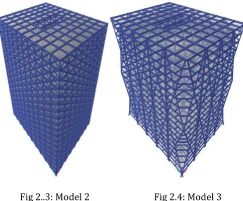
Fig 2.1: Model 2 Fig 2.2: Model 3
[image:2.595.309.561.226.393.2]There are many types of high rise buildings developed by many of the architects and structural engineers. Here, an attempt is made to check the performance of the various kind of building systems against lateral forces caused due to earthquakes. Following models are considered for the comparative study in this paper.
Fig 2..3: Model 2 Fig 2.4: Model 3
The above figures are modelled using ETABS software v 2015 where 1 is conventional frame structure, 2 is core wall structure, 3 shear wall structure, model-4 bracing structure and model-5 is diagrid structure.
3. Analysis and Results of Building Structures
For earthquake to occur, the main phenomenon is the ground motion acceleration with time. Equivalent static analysis is an analysis in which it refers to the basic elastic behavior. In this project we have calculated the results for equivalent static analysis along x and y directions for the structures considered.
3.1 Equivalent Static Analysis of Storey Displacement along X and Y direction
The below figures represent results for storey displacement using equivalent static analysis along X-direction and Y-X-direction respectively, for all the five models namely, model 1- conventional frame structure, model 2- core wall structure, model 3-shear wall structure, model 4-bracing structure and model 5-diagrid structure.
[image:2.595.41.283.356.556.2]Fig 3.1: Equivalent Static Analysis of storey displacement along X-direction
Fig 3.2: Equivalent Static Analysis of storey displacement along Y-direction
3.2 Response Spectrum Analysis of Storey Displacement along X and Y direction
[image:2.595.308.560.437.604.2]© 2017, IRJET | Impact Factor value: 5.181 | ISO 9001:2008 Certified Journal
| Page 1638
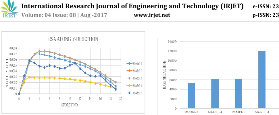
Figure 3.3 and 3.4 shows the results of response spectrum analysis of storey displacement along x and y direction
[image:3.595.39.288.143.321.2]respectivelyfor all the five models as mentioned above.
[image:3.595.307.562.316.453.2]Fig 3.3: Response Spectrum Analysis of storey displacement along X-direction
Fig 3.4: Response Spectrum Analysis of storey displacement along Y-direction
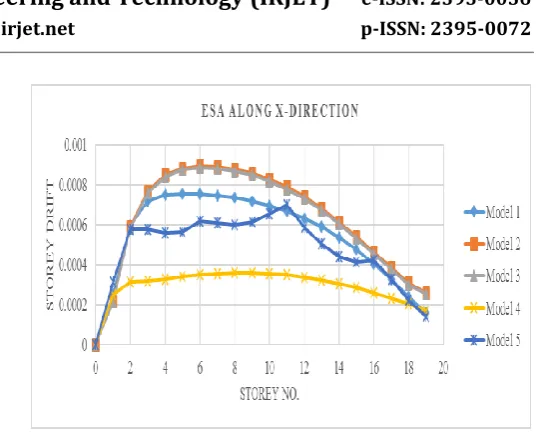
3.3 Equivalent Static Analysis of storey drift along X and Y direction
From the numerical values got after running the analysis, it is noted that, as the storey of the structure is increased storey drift values also increases upto certain storey level and it again reduces. Compared to other structures diagrid structural system and bracing structural building system shows good storey drift results.
Fig 3.5: Equivalent Static Analysis of storey drift along X-direction
Fig 3.6: Equivalent Static Analysis of storey drift along Y-direction
Figure 3.5 and 3.6 portrays the equivalent static analysis results for storey drift along X and Y directions respectively. In the figure it is clear that model-5 which is diagrid structure shows very good results compared to conventional, core wall and shear wall structure but bracing structure shows even better result.
[image:3.595.37.289.364.549.2] [image:3.595.310.560.582.727.2]© 2017, IRJET | Impact Factor value: 5.181 | ISO 9001:2008 Certified Journal
| Page 1639
Fig 3.8: Response Spectrum Analysis of storey drift along Y-direction
Referring to the storey drift results it is observed that, the storey drift curves are increasing uniformly throughout the height of the building structure. Same storey drift curves are observed in both kind of analysis. But storey drift patterns of conventional frame, core wall and shear wall buildings are observed more uniform. In case of the diagrid buildings highly conservative results are observed. Maximum storey drift is observed at the lower portion of the conventional frame, core wall and shear wall, while in diagrid buildings sudden variations are observed at storeys where the diagrid sections are changed.
3.4 Equivalent Static Analysis of Base shear along X and Y direction
Figure 3.9 and figure 3.10 shows the comparison of maximum base shear for all the building systems using both equivalent static analysis and response spectrum analysis. As the building systems are kept symmetric the base shear will be the same in both lateral and transverse directions. But as the bracing structure is stiffer than diagrid structure it draws more lateral force and hence it has larger base shear compared to diagrid structure system and other building system.
[image:4.595.274.560.63.248.2]Fig 3.9: Equivalent Static Analysis of Base Shear along X-direction
Fig 3.10: Equivalent Static Analysis of Base Shear along Y-direction
3.5 Time Period
From the below figure, comparison of time period for all the building systems is examined and it is observed. that as the building height increases, time period of diagrid remains lower than that of the conventional frame, core wall and shear wall building systems. But bracing model comes out with far more effective results with reference to diagrid building system Thus it is observed that the diagrid and bracing structural systems are stiffer than the other conventional structural systems.
Fig 3.11: Time Period
4. CONCLUSIONS
[image:4.595.307.560.435.601.2] [image:4.595.34.287.583.732.2]© 2017, IRJET | Impact Factor value: 5.181 | ISO 9001:2008 Certified Journal
| Page 1640
case of bracing structure is even more high when compared to diagrid structure.
Figure 3.9 and 3.10 shows the comparison of maximum base shear for all the building systems with reference to equivalent static analysis. As the building systems are kept symmetric the base shear will be the same in both lateral and transverse directions. But as the bracing structure is stiffer than diagrid structure it draws more lateral force and hence it has larger base shear compared to diagrid structure system and other building system.
Figure 3.11 represents the contrast of the time period for different building systems considered in this study. It is observed that as the building altitude increases the period of the building systems remains low. Least period represents the stiffer building. Hence from the numerical outcomes from the analysis carried out, diagrid structure and bracing structure proves to be the stiffer building systems compared to the other conventional frame building systems.
From the numerical values got after running the analysis, it is noted that, as the storey of the structure is increased storey drift values also increases upto certain storey level and it again reduces. Compared to other structures diagrid structural system and bracing structural building system shows good storey drift results.
Diagrid structural system with columns gives more opposition in the building which makes system more operative.
Diagrid structural system gives more flexibility in planning inner area and elevation of the building.
Displacements on each storey and storey drifts are noticed to be less in diagrid systems when matched with conventional frame
Due to diagonal columns on its periphery, diagrid shows better resistance to lateral loads and due to this, inner columns get relaxed and carry only gravity loads. While in conventional building both inner.
The time periods are less in diagrid system. Lesser values of the time period than conventional mode, core wall model and shear wall model shows that diagrid models are less flexible against seismic vibrations.
In comparison to conventional building, diagrid buildings are more aesthetic in look and it becomes important for high rise buildings.
So from results and comparison with conventional building one can adopt diagrid structure for better lateral load resistance.
5. SCOPE FOR FUTURE STUDY
Hybrid structure with core wall and bracing with moment resisting frame can be studied. Diagrid structures can be studied using base oscillators and dampers. Diagrid structures without corner columns can be studied Diagrid structures with the application of both wind and earthquake analysis be studied. Making use of triangulated diagrids in other high rise buildings like, tubular structure and outrigger structure can be done and studied on different terrain categories with different zones.
REFERENCES
[1] Manthan I Shah, Sneha V Mevada, Vishal B Patel. “Comparative Study of Diagrid Structures with Conventional Frame Structures”. International Journal of Engineering Research and Applications. Vol-6 pg.no: 22-29
[2] Raghunath D Deshpande, Sadanand M Patil, Subramanya Ratan. “Analysis and Comparison of Diagrid and Conventional Structural System”. International Research Journal of Engineering and Technology. Vol-2 pg.no:2295-2300
[3] Amol V Gorle, S.D. Gowardhan. “Optimum Performance of Diagrid Structure”. International Journal of Engineering Research. Vol-5 pg.no:583-585
[4] Nishith B Panchal, Vinubhai R Patel. “Diagrid Structural System: Strategies to Reduce Lateral Forces On High-Rise Buildings”. International Journal of Research in Engineering and Technology. Vol 3 pg.no:374-378
[5] Saket Yadav, Dr. Vivek Garg. “Advantages of Steel Diagrid Building Over Conventional