© 2017, IRJET | Impact Factor value: 5.181 | ISO 9001:2008 Certified Journal | Page 2501
EFFECT OF POSITIONING AND CONFIGURATION OF SHEAR WALLS ON
SEISMIC PERFORMANCE OF RC BUILDING RESTING ON HILLY AND
PLAIN TERRAIN
Anjali B U
1, Dr. Gopisiddappa
21
P.G. Student, Dept. Of Civil Engineering, PES College of Engineering, Mandya , Karnataka, India
2HOD and Professor, Dept. Of Civil Engineering, PES College of Engineering, Mandya, Karnataka, India
---***---Abstract – Hill buildings are different from those inplains, they are irregular and unsymmetrical in vertical and horizontal planes, and torsionally coupled. Shear wall systems are one of the most frequently used lateral load withstanding systems in high rise buildings. Shear wall has high in plane stiffness and strength which can be used to simultaneously withstand large horizontal loads and support gravity loads. To make better the seismic performance of building on hilly terrain the shear walls plays a very relevant role. Hence in this study the attempt is made to analyse the multi-storey buildings on hilly and plain terrain with and without shear walls. The performance of the building with different configurations of shear walls such as straight, T shape, C shape and L shape is studied. The RCC buildings models having (G+8) storeys with and without shear walls resting on plain and hilly terrain (slope 10⁰) are considered. The response spectrum analysis is carried out using structural analysis tool ETABS and building with various configurations is compared with time period, base shear and story displacements. It is observed that straight shape shear wall configuration proves to be better for buildings on straight is suitable, along with shear wall plain terrain as it gives maximum displacement.
Key Words: Hilly Terrain, Plain Terrain, Shear wall System and Response spectrum analysis.
1. INTRODUCTION
Earthquake is the most calamitous due to its unpredictability and huge power of devastation. Earthquakes themselves do not kill people, rather the extremely loss of human lives and properties occur due to the destruction of structures. Many research works have been directed worldwide in last few decades to inquire the cause of failure of different types of buildings under very bad seismic excitations. Large destruction of high-rise as well as low-rise buildings in recent devastating earthquake proves that in developing countries
Earthquake occurs due to quickly movement of the tectonic plates as a result it release large amount of energy in a few seconds. The collision of this function is most injurious because it affects large proximity, and which occurs sudden and unpredictable. It causes
considerable scale loss of life and property and damages important services such as, sewerage systems, communication, power, transport, and water supply etc.
To defeat from the difficulty we need to find out the seismic performance and lateral stability of the building structure. Many investigation have been conducted on elastic and inelastic seismic behaviour of asymmetric systems to find out the reason of seismic susceptibility of such structures. Hill slope these buildings step back towards the hill slope and at the same time they may own set-back also, having unequal heights at the same floor level the column of hill building rests at various levels on slope. The seismic answer of multi storey buildings can be enhanced by incorporating a shear wall. Shear walls systems are one of
The most commonly used lateral load resting systems in high-rise buildings. Shear walls have very high in plane stiffness and strength, which can be used to simultaneously withstand large horizontal loads and support gravity loads, making them quite beneficial. In this paper effort has been made to the seismic response of RC buildings with various shear walls configurations such as straight shape, L shape, T shape and C shape on plain and hilly terrain. The main objectives of the study are
1.1 OBJECTIVES
1) To study seismic performance of building with and without shear walls resting on plain and hilly terrain.
2) To study the effectiveness of different shear walls configurations on seismic action of building resting on plain and hilly terrain such as straight shape, L shape, T shape and channel shape.
3) To compare effect of positioning of shear walls on seismic performance of building on plain and hilly terrain.
2. MODELING AND ANALYSIS
© 2017, IRJET | Impact Factor value: 5.181 | ISO 9001:2008 Certified Journal | Page 2502
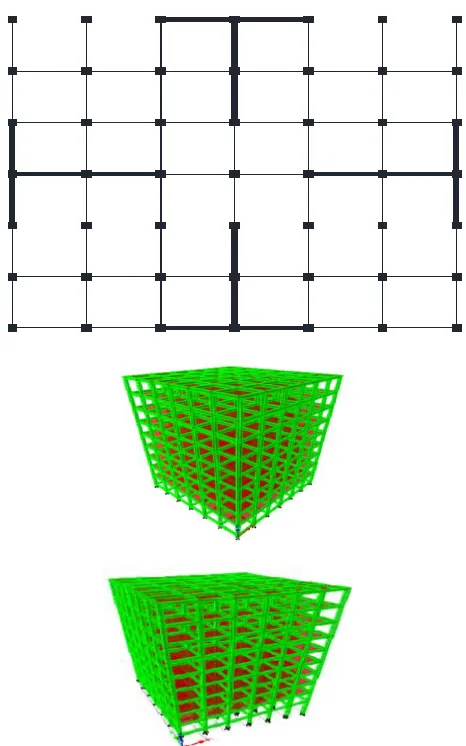
and diaphragm constraint is designated. The area loads are applied on slabs. Building modeled as bare frame however the dead weight of infill is designated as uniformly distributed load over beams. The shear walls are modeled by the wide column analogy method and fixed supports are assigned for both shear walls and columns. To increase the seismic response of building various shear walls configurations are selected.
2.1 Load Combinations:
The following load combination has been used for calculating the member forces and for the comparing its results as per IS 1893 (Part 1): 2002.
1.5(DL+IL)
1.2 (DL+IL±EL)
1.5 (DL±EL)
0.9 DL±1.5 EL
3. BUILDING DESCRIPTION
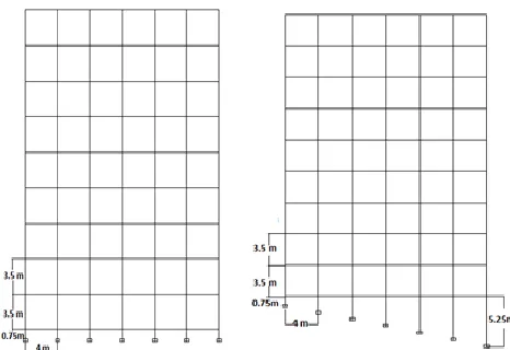
[image:2.596.39.272.478.638.2]Model consists of G+8 storey RCC building having six bays in each direction, each bay is having width of 4m. The story height for each floor and plinth height is kept as 3.5m and 0.75m respectively. The RCC frame consists of beam and column of sizes 0.3m x 0.45m and 0.45 x 0.45m respectively and also slab thickness is taken as 140mm. The models are analyzed on plain as well as hilly terrain (slope 10⁰). The frames on plain and hilly terrain under consideration for present study is as shown in Fig.1. The concrete of grade M30 and steel of grade Fe 415 are used.
Fig-1: Elevation of building on plain and 10⁰ sloping ground
3.1 Loads
3.1.1 Dead loads
Self-weight of building is automatically calculated by the
software.
Super imposed dead load (Floor finishes or water proofing’s) all floors ₌1.875kN/m2
3.1.2 Live loads
Live load on floor₌4kN/m2 Live load on roof=1.5kN/m2
Models considered on plain and sloping terrain are Model 1 without shear wall Fig 2
Model 2 with straight shape shear walls Fig 3
Model 3 with L-shape shear walls Fig 4
Model 4 with T-shape shear walls Fig 5
Model 5 with Channel shape (C shape) shear walls Fig 6
© 2017, IRJET | Impact Factor value: 5.181 | ISO 9001:2008 Certified Journal | Page 2503
Fig -2: Without shear wall on plain and hilly terrain
[image:3.596.322.552.379.510.2]Fig-3:Straight shape shear walls on plain and hilly terrain
[image:3.596.320.562.544.725.2]Fig-4: L- shape shear walls on plain and hilly terrain
Fig-5: T-shape shear walls on plain and hilly terrain
4. METHOD OF ANALYSIS
© 2017, IRJET | Impact Factor value: 5.181 | ISO 9001:2008 Certified Journal | Page 2504
(Part 1): 2002. As per codal provisions dynamic results are standardized by multiplying with a base shear ratio Vb/VB, where Vb is the base shear evaluation based on time period given by empirical equation and, VB is the base shear from dynamic analysis, if Vb/VB ratio is more than one. Damping considered for all the modes of vibration was five percent. For determining the seismic response of the buildings in different directions for ground motion the response spectrum analysis was conducted in longitudinal and transverse direction (X and Y). The other parameters used in the seismic analysis were, seismic zone (V), zone factor 0.36, importance factor 1, special moment resisting frame (SMRF) for all models with a response reduction factor of 5. The default number of modes (i.e. 12) in software was used and the modal responses were combined using CQC method. The response spectra for soft soil sites with 5% damping as per IS 1893 (Part 1): 2002 is utilized in response spectrum analysis.
5. RESULTS AND DISCUSSION
The results of the present study are divided in two categories as follows:
Fig-6: C-shape shear walls on plain and hilly terrain
5.1 Plain Terrain
From the results procured from this study it can be noticed that the incorporation of shear wall in RCC frame increases the base shear due to increase in lateral stiffness. Hence time period of structure reduces. Due to increase in stiffness the story displacement of structure is considerably get reduces. The base shear gets increase approximately by 2.1-14%. The model 4 (T-shape) has minimum value of base shear among all other shear walls configurations. Time period get reduced by approximately by 70% as compared to model 1 (without shear wall) and model 2 ( Straight shape) has minimum time period. The reduction in roof displacement is observed to be 89%, 84%, 81% and 83% for model 2, 3, 4 and 5 as compared to model 1(without shear wall). The results procured from this study on plain and hilly terrain are represented in Fig 7, 8 and 9 for different models.
1) Fundamental time period
Fig-7:Variation of time period on plain terrain
2) Base shear
Fig-8: Variation of base shear on plain terrain
3) Story displacement
Fig-9: Variation of story displacement on plain terrain 0 0.5 1 1.5 2
Model 1 Model 2 Model 3 Model 4 Model 5
Time p er io d in sec
Fundamental time period
4200 4400 4600 4800 5000 5200 5400
Model 1 Model 2 Model 3 Model 4 Model 5
B a se sh ea r in k N
Base shear
0 10 20 30 40 50 60 70 800 5 10 15
© 2017, IRJET | Impact Factor value: 5.181 | ISO 9001:2008 Certified Journal | Page 2505
5.2 Hilly Terrain
From the results obtained in present study it is observed that base shear of buildings on slopes for different shear wall configurations is increased by 3% . The base shear is minimum for the model 3 (L shape). The time period get reduced by 70% as compared to model 1 (without shear wall). The story displacement observed in the direction parallel to slope is more as compared to displacement in transverse direction. The story displacement reduced in X direction and in Y direction similar to that of models on plain terrain due to provision of shear wall. The seismic performance of the buildings on slope is as presented in Fig-10, 11, 12 and 13.
1) Time Period
Fig-10: Variation of time period on hilly terrain
2) Base shear
Fig-11: Variation of base shear on hilly terrain
3) Story displacement
Fig-12: Story displacement on hilly terrain
Fig-13: Story displacement on hilly terrain
6. CONCLUSIONS
1) The buildings on hilly terrain are more vulnerable to the seismic activity than the buildings on leveled ground as hill buildings are very irregular. Though the buildings on slope having the lesser values of base shear and displacement, the time period are higher in hill buildings.
2) The L-shape shear wall proves to be better for buildings on slope which gives comparatively less base shear along the slope and straight shape shear walls configuration is efficient in resisting roof displacement.
3) The T-shape shear walls gives more story displacement and time period for buildings on slopes as compared to other configuration.
4) The straight shape shear wall configuration proves to be better for buildings on plain terrain as it gives the minimum displacement and time period.
0 0.2 0.4 0.6 0.8 1 1.2 1.4 1.6 1.8
Model 1 Model 2 Model 3 Model 4 Model 5
Time p er io d in sec
Fundamental time period
4100 4150 4200 4250 4300 4350
Model 1 Model 2 Model 3 Model 4 Model 5
Ba se sh ea r in kN
Base shear
0 20 40 60 800 5 10 15
D isp la cement in mm
Storey no.
Story displacement in X direction
Model 1 Model 2 Model 3 Model 4 Model 5 0 20 40 60 80 100
0 5 10 15
D isp la cement in mm Storey no.
Story displacement in Y direction
© 2017, IRJET | Impact Factor value: 5.181 | ISO 9001:2008 Certified Journal | Page 2506
REFERENCES
1) B.G. Birajdar and S. S. Nalawade, (2004), “Seismic analysis of buildings resting on sloping ground”, 13th World Conference on Earthquake Engineering, Vancouver, B.C. , Canada, Paper No. 1472.
2) S.M. Nagargoje and K.S. Sable, “Seismic performance of multi-storey building on sloping ground”, Elixir International Journal, 2012.
3) Rayyan-Ul-Hasan Siddiqui and Vidyadhara H.S., 2013, “Seismic Analysis of Earthquake Resistant Multi Bay Multi Storied 3D – RC Frame”, International Journal of Engineering Research and Technology (IJRET), ISSN: 2278-0181, Volume 2, Issue 10, October 2013.
4) S.K. Hirde and Ms S.T. Charajan, (2009), “Effect of various positions of reinforced concrete shear walls on seismic performance of buildings having soft bottom storey”, ISSE Journal, Volume 11-1.
5) Halkude S.A, M.G. Kalyanshetti and V.D. Ingle, 2013, “Seismic Analysis of Buildings Resting on Sloping Ground with Varying Number of Bays and Hill Slopes”, International Journal of Engineering Research and Technology (IJERT), ISSN: 2278-0181 Vol. 2, Issue 12.
6) V. Govalkar, P.J. Salunke and N.G. Gore, 2014, “Analysis of bare frame and in filled frame with different position of shear wall”, International Journal of Recent Technology and Engineering (IJRTE), ISSN: 2277-3878, Volume-3 Issue-3,pp.67-72.
7) I.S.456 2000, “Plain and Reinforced Concrete-Code of Practice”, Bureau of Indian Standards, New Delhi. 8) IS 193 (Part I): (2002), “ Criteria for Earthquake