© 2017, IRJET | Impact Factor value: 5.181 | ISO 9001:2008 Certified Journal
| Page 3197
OPTIMIZATION OF CUTTING PARAMETERS BASED ON TAUGCHI
METHOD OF AISI316 USING CNC LATHE MACHINE
Lakhan Singh
1, Rajeev Choudhary
2, Deepak Kumar Juneja
31
Research Scholar, Department of Mechanical Engineering, Gaeta Engineering College, Panipat, Haryana
2Research Scholar, Department of Mechanical Engineering, IIT (BHU), Varanasi (U.P)
3
Head of Department Department of Mechanical Engineering, Gaeta Engineering College, Panipat, Haryana
---***---Abstract-The main aim of this research work is focusedon the analysis of optimum cutting conditions to get lowest surface roughness in CNC turning of austenitic stainless steel AISI 316 using carbide insert coated with TiN under dry condition. Taguchi method is used for design this experiment and the total 27 experiment performed to find out optimum values of level of different factors in order to minimize surface roughness of austenitic stainless steel AISI 316 in turning. The analysis of variance (ANOVA) is used for calculating the percentage of contribution of each factor in quality of surface roughness. The result show that the maximum effect on surface roughness produce by feed and the minimum effect on surface roughness produce by depth of cut. The surface of workpiece is least effected by cutting speed.
Keywords: Taguchi’s Techniques, ANOVA. CNC Turning, Surface roughness.
1. INTRODUCTION
The main aim of this research work to find out the factor affecting the surface roughness. This research work is conducting for optimizing these factors. Now a day’s it is great challenge for obtained high quality, good surface finish and high material removal rate for every machining enterprises. The quality of every product is depending on surface smoothness. So in this research work we shall obtain a group of factor on which surface roughness is minimum and surface smoothness maximum. The group of factor is determining with help of Taugchi method in this present work. This research work concerned with the determination of optimal turning parameters for reduced roughness and increased hardness of the machined surfaces while turning of workpiece austenitic stainless steel AISI 316 using carbide insert coated with TiN under dry condition.Yang et al. [1] conducted an experiment to studythe optimize the turning operation of S45C steel bars using tungsten carbide cutting tools and reported that cutting speed, feed rate, and depth of cut were the significant cutting parameters for affecting surface roughness. They found out the contribution order of the cutting parameters for surface roughness is feed rate, then depth of cut, and
© 2017, IRJET | Impact Factor value: 5.181 | ISO 9001:2008 Certified Journal
| Page 3198
piece grade, cutting tool coating top layer and cuttingspeed were conducted on cutting forces and machined surface roughness. Results show that surface finish values decreased with increasing in cutting speed until a minimum value was reached, beyond which they increased. Sujan Debnath et al. [8]. conducted an experimental to study to investigated the effect of various cutting fluid levels and cutting parameters on surface roughness and tool wear of mild steel bar using a TiCN + Al2O3 + TiN coated carbide tool by using Taguchi and orthogonal array in C NC turning process. Llhan Asilturk et al. [9] conducted an experimental to study the modelling of experimental data of surface roughness of Co28Cr6Mo medical alloy machined on a CNC lathe. Three cutting parameters spindle rotational speed, feed rate, and depth of cut were used and tool tip radius based on the Taguchi orthogonal test design and RSM. Supriya Sahu et al. [10] investigated the optimum cutting conditions to get lowest surface roughness in turning and the performance of multi-layer TiN coated tool in machining of hardened steel (AISI 4340 steel) under high speed turning and found the effect of cutting parameters (speed, feed, and depth of cut) on surface roughness using Taguchi method. Feng and Wang [11] conducted an experiment to study for obtained the surface roughness in finish turning operation by developing an empirical model through considering working parameters. R.K.Suresh et.al [12] focused to investigate the effect of cutting parameters on EN-41 B alloy steel using Taguchi technique. An accurate regression model is developed for material removal rate. Result show that feed is the most dominant parameter for MRR.R. B. Mandavia [13]conducted an experiment to study to effect of different input parameters temperature, cutting speed, feed etc. And their effect on surface roughness, hardness, material removal rate, tool wear, tool life. Taguchi method was used for designed this experiment. Based on the study it is observed that depth of cut, speed and feed affected the surface roughness while turning of austenitic stainless steel AISI316 significantly. So more study and investigation is required to investigate the factor affected the surface roughness under various operations.
2. DESIGN OF EXPERIMENTS
This presented work is based on Taguchi method of design of experiments. Taguchi strategy is effective technique for planning process that works reliably and ideally finished the types of conditions .When number of factor in a design is increase then it is very complex for solution .then a special designed method in which the use of orthogonal array to study the whole parameter space with lesser was suggested by Taguchi.
2.1. Smaller the Better
In situations where you need to limit the events of some undesirable item qualities, you would figure the accompanying S/N proportions/N ratio of smaller the better is given below
(S/N) smaller the better = −10*log (Σ (Y2)/n) Where Y = responses for the given factor level combination
And n = number of responses in the factor level combination.
2.2. Larger the Better
Cases of this kind of building issue are mileage (miles per gallon) of a car, quality of solid, resistance of protecting materials, and so forth. The accompanying S/N
proportion ought to be utilized and this is given below
(S/N) larger the better = −10*log (Σ (1/Y2)/n)
Where Y = responses for the given factor level combination
And n = number of responses in the factor level combination.
2.3. Nominal the better
In case of nominal the better you have a fixed signal value (nominal value), and the variance around this value can be considered the result of noise factors:
(S/N) nominal the better = −10*log (s2)
Where Y = responses for the given factor level combination
And n = number of responses in the factor level combination.
3 .EXPERIMENTAL SETUP
Experimental setup in this research work is consist of workpiece (AISI316), CNC lathe machine, Micrometre, tungsten carbide insert type cutting tool and surface tester.
4. WORKPIECE MATERIAL
© 2017, IRJET | Impact Factor value: 5.181 | ISO 9001:2008 Certified Journal
| Page 3199
Table- 1: The Chemical Composition of AISI316.Element Weight %
C 0.058
S 0.019
Mo 2.086
Cu 0.559
Si 0.349
Cr 16.536
V 0.014
[image:3.595.42.563.499.772.2]Mn 1.080
Table- 2: Mechanical Properties of AISI 316.
Yield Strength 290 MPa
Modulus of elasticity 193 MPa Tensile strength 580 MPa
Density 800 kg/mm3
BHN 217
4. CUTTING TOOL INSERTS
Tungsten inserts carbide type cutting tool is used for turning of stainless steel AISI316 in current work. The nomenclature of cutting inserts is given below. In this research paper cutting tool insert TNMG160408 is use for turning.
5. CNC LATHE MACHINE
The CNC lathe machine “Midas 8i” is used for turning of stainless steel AISI316 in this present work. This machine is manufacturing by GALAXY MACHINERY PVT. LTD
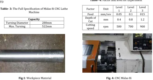
Table- 3: The Full Specification of Midas 8i CNC Lathe Machine
Capacity
Turning Diameter 280mm
Max. Turning 522mm
Length Maximum Swing
Clearance Diameter of Over
Carriage
230mm
Maximum Swing Clearance Diameter over
Way Covers
430mm
Chuck
Chuck Size 210 mm
Bar Capacity 50 mm
Spindle Drive
Spindle Power 40 rpm – 4000 rpm
Range of Spindle 12 hp-10 hp
6. SURFACE TESTER
The surface roughness of workpiece in this research work is measuring by Mitutoyo SJ-201P.The surface roughness of workpiece will trace by a pick-up which attached to the detector SJ-201P.
7. FACTORS AND THEIR LEVEL
The factor and there level used in this research work are given below.
1. Cutting speed in rpm 2. Feed in mm/rev 3. Depth of cut in mm
Table- 4: Factor and level for Experiment
Factor Unit Level 1 Level 2 Level 3
Feed mm/rev 0.05 0.1 015
Depth of
Cut mm 0.4 0.8 1.2
Cutting
speed rpm 500 700 900
[image:3.595.302.559.514.752.2]
© 2017, IRJET | Impact Factor value: 5.181 | ISO 9001:2008 Certified Journal
| Page 3200
[image:4.595.318.560.111.252.2]
Fig.2: Cutting Tool Inserts Fig.5: Workpiece Turning
[image:4.595.37.263.112.253.2][image:4.595.38.262.285.438.2]
Fig.3: Workpiece after Machining Fig.6: Mitutoyo SJ-201P (Surface Tester)
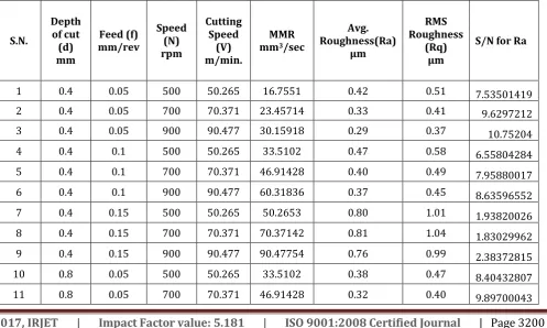
Table -5: Surface Roughness, MRR and S/N ratio
S.N.
Depth of cut (d) mm
Feed (f) mm/rev
Speed (N) rpm
Cutting Speed
(V) m/min.
MMR mm3/sec
Avg.
Roughness(Ra) µm
RMS Roughness
(Rq) µm
S/N for Ra
1 0.4 0.05 500 50.265 16.7551 0.42 0.51 7.53501419
2 0.4 0.05 700 70.371 23.45714 0.33 0.41 9.6297212
3 0.4 0.05 900 90.477 30.15918 0.29 0.37 10.75204
4 0.4 0.1 500 50.265 33.5102 0.47 0.58 6.55804284
5 0.4 0.1 700 70.371 46.91428 0.40 0.49 7.95880017
6 0.4 0.1 900 90.477 60.31836 0.37 0.45 8.63596552
7 0.4 0.15 500 50.265 50.2653 0.80 1.01 1.93820026
8 0.4 0.15 700 70.371 70.37142 0.81 1.04 1.83029962
9 0.4 0.15 900 90.477 90.47754 0.76 0.99 2.38372815
10 0.8 0.05 500 50.265 33.5102 0.38 0.47 8.40432807
[image:4.595.54.552.494.792.2]© 2017, IRJET | Impact Factor value: 5.181 | ISO 9001:2008 Certified Journal
| Page 3201
12 0.8 0.05 900 90.477 60.31836 0.24 0.30 12.3957752
13 0.8 0.1 500 50.265 67.0204 0.45 0.55 6.93574972
14 0.8 0.1 700 70.371 93.82856 0.40 0.49 7.95880017
15 0.8 0.1 900 90.477 120.63672 0.42 0.51 7.53501419
16 0.8 0.15 500 50.265 100.5306 0.77 0.95 2.2701855
17 0.8 0.15 700 70.371 140.74284 0.79 1.00 2.04745817
18 0.8 0.15 900 90.477 180.95508 0.78 1.00 2.15810795
19 1.2 0.05 500 50.265 50.2653 0.34 0.44 9.37042166
20 1.2 0.05 700 70.371 70.37142 0.33 0.42 9.6297212
21 1.2 0.05 900 90.477 90.47754 0.32 0.41 9.89700043
22 1.2 0.1 500 50.265 100.5306 0.44 0.53 7.13094647
23 1.2 0.1 700 70.371 140.74284 0.42 0.51 7.53501419
24 1.2 0.1 900 90.477 180.95508 0.41 0.50 7.74432287
25 1.2 0.15 500 50.265 150.7959 0.84 1.08 1.51441428
26 1.2 0.15 700 70.371 211.11426 0.82 1.02 1.72372295
27 1.2 0.15 900 90.477 271.43262 0.82 1.03 1.72372295
8. RESULT AND DISCUSSION
Table- 6: Response Table for Signal to Noise Ratio
Level depth of
cut (mm) (mm/rev) feed (rpm) speed
1 6.358 9.723 4.740
2 6.622 7.555 6.468
3 6.252 1.954 7.025
Delta 0.370 7.769 1.285
Rank 3 1 2
Fig.7: The Main Effect Plot for SN ratios Data Means
From the plot diagram it is clear that when depth of cut is increase then mean of SN ratio is increase at a point but after increasing in depth of cut mean of SN ratio is decrease. When feed is increase then means of SN ratio is decrease. When speed is increase then mean of SN ratio is also increase.
Fig.9: Surface Plot of Ra Vs Feed, and Depth of Cut
This figure shows variation of surface roughness with feed and depth of cut. We can obtain the minimum value of surface roughness with respect to feed and depth of cut.
0.50 0.75 1.00 0.2
0.4 0.6
0.10
0.05 0 1.25
0.10 0.15 0.8
a R
) v e r / m m ( d e e f
) m m ( t u c f o h t p e d
urface Plot of Ra vs feed
© 2017, IRJET | Impact Factor value: 5.181 | ISO 9001:2008 Certified Journal
| Page 3202
Fig.10: Surface Plot of Ra Vs Speed, and Depth of Cut [image:6.595.311.570.115.321.2]This figure shows variation of surface roughness with feed and depth of cut. We can obtain the minimum value of surface roughness with respect to speed and depth of cut.
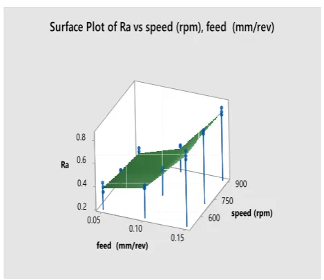
Fig. 11: Surface Plot of Ra vs Speed, and Feed
This figure shows variation of surface roughness with feed and depth of cut. We can obtain the minimum value of surface roughness with respect to speed and feed.
9. REGRESSION EQUATION
It is use for obtained the relationship between depth of cut, speed and fee rate with surface roughness.
Ra =0.1346 + 0.0125depth of cut (mm) + 3.689feed (mm/rev) -0.000139 speed (rpm)
[image:6.595.40.275.399.602.2]10. ANOVA
Table- 7: Analysis of Variance
Model Summary
S R-sq R-sq(adj) R-sq(prep)
0.0293888 98.50% 98.04% 97.26%
Analysis of variance shows the contribution of the parameter which effect on surface roughness.
CONCLUSION
In this research work we investigate the effects of cutting parameters depth of cut, feed and speed on surface roughness of AISI316 stainless steel. Finally we obtained the values of selected machining parameters for affecting surface roughness. The optimum value of depth of cut 0.8 mm; feed is 0.05 mm/rev, and speed 900 rpm. Corresponding to these values of parameters the minimum surface roughness recorded.
From regression relation the value obtained corresponding to optimum values of parameters was 0.2539 µm. And there was no value in of surface roughness is recorded less than this value during 27 experiments. Hence result was validated.
REFERENCES
[1] Yang. W.H, T. Y.S.(1998). Design optimization of cutting parameters for turning operations based on the Taguchi method, Journal of Material Processing Technology. 84(13), 122-129.
[2] Zhang, J.Z, Chen. J.C, Kirby, E.D. (2007). Surface roughness optimization in an end-milling operation using the Taguchi design method, Journal of Material Processing Technology. 184(1-3), 233-239. 0.50 0.75 1.00 0.2 0.4 0.6 600 0 1.25 750 900 0.8 a R ) m p r( d e e p s ) m m ( t u c f o h t p e d
urface Plot of Ra vs speed (rpm), depth of cut (mm) S 0.05 0.10 0.2 0.4 0.6 600 0.15 750 900 0.8 a R ) m p r( d e e p s ) v e r / m m ( d e e f
urface Plot of Ra vs sp
S e d (rpm), feed (mm/rev)e
Source DF Adj SS Adj MS F-Value P-Value depth
of cut (mm)
2 0.00201 0.001004 1.16 0.333
feed
(mm/rev) 2 1.11454 0.557270 644.21 0.000
speed
(rpm) 2 0.01401 0.007004 8.11 0.003
Error 20 0.01727 0.000864
© 2017, IRJET | Impact Factor value: 5.181 | ISO 9001:2008 Certified Journal
| Page 3203
[3] N. M, G. H, Sur. G. (2007).Application of Taguchimethod in the optimization of cutting parameters for surface roughness in turning, Materials & Design. 28(4): 1379-1385.
[4] J. A. Ghani,. I. A. Chodhury, and Hassan, H.H. 2004.Application of Taguchi method in the optimization of end milling parameters, Journal of Material Processing Technology. 145(1): 84-92.
[5] Pranav R. Kshirsagar. (2008). Optimization of Surface Roughness of EN8 Steel in CNC Turning Operation by Taguchi Concept, International Journal of advanced Technology Engineering and Science. ISSN: 2348-7550.
[6] S. Thamizhmanii, S. Hasan. (2011). Machinability of hard martensitic stainless steel and hard alloy steel by CBN and PCBN tools by turning process, Proceedings of the World Congress on Engineering, 1(1): 554-559.
[7] I.Ciftci. (2006). Machining of austenitic stainless steels using CVD multilayer coated cemented carbide tools. Tribology International, 39(6): 565-569.
[8] S. Debnath, M. Mohan Reddy, Qua Sok Yi. (2016).Influence of cutting fluid conditions and cutting parameters on surface roughness and tool wear in turning process using Taguchi method. Measurement, 78:111–119.
[9] Llhan Asilturk, Suleyman Neseli, Mehmet Alperlnce.(2016).Optimisation of parameters affecting surface roughness of Co28Cr6Mo medical material during CNC lathe machining by using the Taguchi and RSM methods, Measurement. 78:120–128.
[10] S. Sahu, B. B. Choudhury. (2015). Optimization
of Surface Roughness Using Taguchi
Methodology & Prediction of Tool Wear in Hard Turning Tools. Materials Today Proceedings, 4th International Conference on Materials Processing and Characterization, 2 (4–5): 2615– 2623.
[11] Feng C. X, Wang X. (2002). Development of
[12] R.K.Suresh, G. Krishnaiah.(2013).Parametric Optimization on single objective Dry Turning using Taguchi Method. International Journal of Innovations in Engineering and Technology, vol.2.