© 2017, IRJET | Impact Factor value: 5.181 | ISO 9001:2008 Certified Journal | Page 1458
CFD ANALYSIS ON LOUVERED FIN
P.Prasad
1, L.S.V Prasad
21
Student, M. Tech Thermal Engineering, Andhra University, Visakhapatnam, India
2
Professor, Dept. of Mechanical Engineering, Andhra University, Visakhapatnam, India
---***---Abstract-Radiators are used to transfer thermal energy
from one medium to another for the purpose of cooling. They are used for cooling internal combustion engines, mainly in automobiles, railway locomotives, stationary power generating plants etc. The radiator essentially transfers heat from the coolant inside to the surrounding ambient air enhancing performance of the engine. A model of radiator with rectangular and louvered fins are developed using Pro/Engineer and further CFD analysis is performed with ANSYS 14.5 for a relative comparison of geometry of fins on performance of the radiator. Aluminum alloy 6061 is considered in either case to analyze the heat transfer capabilities of louvered fins and rectangular fins.
Key words: Rectangular fin, louvered fin, Aluminum alloy 6061.
1. INTRODUCTION
All internal combustion engines generate a huge amount of heat which is transferred to cylinder walls, piston, valves and other components by conduction. This heat is carried away by the coolant that circulates through the engine, especially around combustion chamber and the cylinder head area of the engine block. The coolant pumped through the engine block, after absorbing the heat is circulated to the radiator where the heat is dissipated to the surrounding atmosphere. The coolant is then transferred back into the engine to repeat the process. Two types of tubular finned radiators are considered for the analysis, louvered fins and rectangular fins respectively made of Aluminum alloy 6061 compared for better heat transfer capabilities. The schematic diagram of thermal resistance considered across the radiator tube is shown in Fig. 1.
Eq 1
Eq 2
Eq 3
Eq 4
Fig-1: Thermal Resistance Diagram
© 2017, IRJET | Impact Factor value: 5.181 | ISO 9001:2008 Certified Journal | Page 1459
2. MODELLING AND THERMAL ANALYSIS OF
RECTANGULAR AND LOUVERED FIN
Geometrical model of rectangular fin and louvered fin are modeled with creo parametric 2.0 and the dimensions of rectangular fin considered for the study is given below.
[image:2.595.309.562.156.343.2]Rectangular fin thickness =0.25mm Rectangular fin length=60mm Rectangular fin width=15mm Rectangular tube diameter=10mm Number of fins considered =16 Rectangular fin height=30mm
Fig-2 :Meshing of rectangular fin
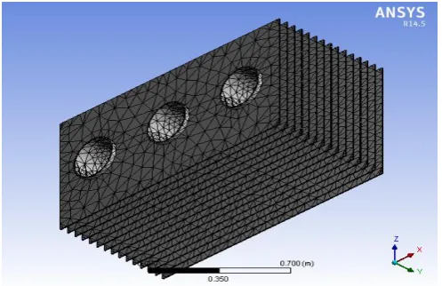
The solid model developed is subjected to meshing using anysis for a rectangular fin as shown in Fig. 2. The number of nodes are 68013 and elements 32799 respectively.The dimensions of louvered fin considered for the study are as follows.
Louvered finned rectangular tube width=7.5 mm Louvered finned rectangular tube length=15mm Number of louvered fins considered =6
Fig-3: Louvered Fin Geometry
The solid model of louvered fin using Creo parametric 2.0 is shown in Fig. 3. The meshed model of the same is shown in Fig. 4. The number of nodes and elements were 463271 and 223429 respectively.
Fig-4: Louvered Fin Meshing
3. ALUMINUM ALLOY 6061 PROPERTIES
The Composition of Al6061 is given below
Mg =0.8 -1.2 % Si =0.4-0.8 % Cu =0.15-0.4 % Cr =0.04-0.35 % Mn =0.15 %
Fe =0.7 %
Zn =0.25 % Ti =0.15 %
Al =95.85%-98.56%
Al6061 has the following advantages
Excellent corrosion resistance to atmosphere condition
Good weldability and brazability
Co efficient of linear thermal expansion 23.5x10⁻⁶m/0C
Thermal conductivity 173 W/m. K Melting point is 5800C
Modulus of elasticity is 70-80 G Pa. Poisson ratio is 0.33
4. THERMO PHYSICAL PROPERTIES OF FLUID
[image:2.595.35.284.265.426.2]© 2017, IRJET | Impact Factor value: 5.181 | ISO 9001:2008 Certified Journal | Page 1460 Ethylene oxide reacts with water to produce ethylene glycol
according to the chemical equation. C2H4 + 2H2O → HO–CH2CH2–OH
0 0.1 0.2 0.3 0.4 0.5 0.6 0.7 0.8
0 25 50 75 100
50/50 Ethylene glycol with water mixture
Pure water
Temperature ,
0C
Th
er
mal
co
n
d
u
cti
vi
ty
,W
/m.
K
Fig-5: Variation of Thermal conductivity of 50/50 Ethylene glycol with water mixture and pure water with temperature
Variation of thermal conductivity of 50/50 Ethylene glycol with water mixture and pure water is shown in Fig. 5. Ethylene glycol mixture certainly has a higher thermal conductivity as compared to water and hence has a better heat transfer capabilities as compared to water. The presence of ethylene glycol could influence freezing temperature of fluid also.
0 2 4 6 8 10 12 14
0 5 25 50 75
50/50 Ethylene glycol with water mixture Pure water
Temperature ,
0C
V
isc
o
si
ty
,
cP
Fig-6: Variation of Viscosity of 50/50 Ethylene glycol with water mixture and pure water with temperature
Fig.6 shows the variation of viscosity with temperature. It is seen that variation of viscosity is found to be marginal within normal operating range as compared to water without compromising much of pump work required.
5. RESULTS AND DISCUSSIONS
The temperature distribution and heat flux distribution for a rectangular fin are shown in Fig. 7 and 8 respectively. A localized high temperature is observed at coolant inlet passage with not much temperature drop along the section of the fin. The thermal conductivity of the aluminum and the geometry of the fins are found to influence the temperature distribution along the tubular radiator.
Fig-7: Temperature Distribution in rectangular fin
Fig-8: Total Heat Flux in rectangular fin
© 2017, IRJET | Impact Factor value: 5.181 | ISO 9001:2008 Certified Journal | Page 1461 heat flux of 31260 W/m2 was found at the entry region of
rectangular finned radiator as shown in Fig.8.
Fig-9: Temperature Distribution: Louvered fin
The temperature distribution across louvered fin radiator is shown in Fig. 9. The maximum and minimum temperature was found to be 750C and 220C respectively. The temperature distribution indicates that the geometry and thermal properties of louvered fin is found to have a profound influence on temperature distribution as compared to rectangular fin. The region in proximity of the coolant passage is found to be at a higher temperature with a significant drop in temperature along the fin.
Fig-10: Total heat flux: Louvered fin
The heat flux density for louvered fin is shown in Fig. 10. The maximum heat flux of 35657W/m2 is found to exist at the entry region with few concentrated zones and there is a proportionate drop in heat flux away from coolant flow passages.
Fig-11: Static pressure in rectangular fin
The pressure distribution along the test section is shown in Fig.11. The maximum static pressure of 34.6 N/m2 is found to exist at the central coolant passages for a rectangular fin. The rest of the test section is found to be exposed to a nominal pressure of 12.6 N/m2.
Fig-12: velocity in rectangular fin
The velocity distribution of coolant through the coolant passages is shown in Fig. 12 for test section with rectangular fin. The maximum velocity of fluid distributions is found to be 0.508 m/s.
© 2017, IRJET | Impact Factor value: 5.181 | ISO 9001:2008 Certified Journal | Page 1462 The static pressure distribution in louvered fin is shown in
Fig. 13. The pressure is found to be distributed across the test section with a maximum pressure of 52.5 N/m2 found to exist across the passages attached to the louvered fins at the entry zone with marginal drop in pressure at the exit of the test section.
Fig-14: Velocity distribution in Louvered fin
The velocity distribution in louvered fin is shown in Fig. 14. The maximum fluid velocity of 1.41 m/s was estimated for the coolant passing through the louvered cross section.
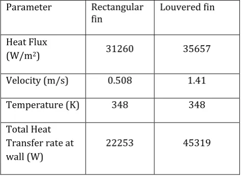
6. COMPARSION OF RECTANGULAR AND LOUVERED
FIN RESULTS
Parameter Rectangular
fin Louvered fin
Heat Flux
(W/m2) 31260 35657
Velocity (m/s) 0.508 1.41
Temperature (K) 348 348
Total Heat Transfer rate at wall (W)
22253 45319
7. CONCLUSIONS
The comparative CFD analysis on rectangular and louvered finned heat exchanger with 50/50 Ethylene glycol and water mixture as working fluid reveals louvered fins exhibit better heat transfer characteristics as compared to rectangular fins. The heat transfer rate was found to be 49% more for louvered fins as compared to rectangular fins. The velocity was found to be significantly higher for louvered fins which might be a contributing factor for enhanced heat transfer rate in louvered fins.
8. REFERENCES
[1] Durgesh Kumar Chavan and Ashok T. Pise Sahin, “Performance Investigation of an Automotive Car Radiator Operated with Nano fluid as a Coolant,” (2010).
[2] Gunnasegaran, “The effect of geometrical Parameters on Heat Transfer Characteristics of compact heat exchanger with Louvered Fins,” (2012).
[3] Junjanna G.C, “Performance Improvement of a Louver-Finned Automobile Radiator Using Conjugate Thermal CFD Analysis,” (2012), pp. 2278-0181.
[4] JP Yadav and Bharat Raj Singh, “Study on Performance Evaluation of Automotive Radiator” (2011), pp. 2229-7111.
[5] Jaya Kumar, “Experimental study and CFD Analysis of Copper radiator for Passenger Cars,” (2016), pp.778-782.
[6] Masoud Asadi, “Minimizing entropy generation for louvered fins plate fin compact heat exchanger,” (2013), pp.35-45.
[7] Manjunath, “Numerical Investigation of automotive radiator louvered fin compact heat exchanger,” (2014), pp.01-14.
[8] Paresh Machhar, Falgun Adroja,”Heat Transfer Enhancement of Automobile Radiator with TiO2/Water Nano fluid,” (2013), pp.2278-0181. [9] Pooranachandran karthik, “Experimental and
[image:5.595.40.279.445.619.2]