© 2018, IRJET | Impact Factor value: 6.171 | ISO 9001:2008 Certified Journal | Page 2150
Comparative Study and Analysis of brake shoe lining using Composite
Material by Ansys14
R.Vigithra
1, S. Hariharan
2, M. Tamilselvan
3, A. Manikandan
41Associate Professor, Department of Mechanical Engineering, Panimalar Institute of Technology, Chennai, India.
2,3,4UG Scholar, Department of Mechanical Engineering, Panimalar Institute of Technology, Chennai, India. ---***--- Abstract — The aim of this project is to increase the life of
the material by reducing the wear rate and to increase the strength of the material. The analysis of brake shoe lining is done by adding it with composite material like Aluminium Al 6061 T6 – & silicon carbide. This composite is fabricated by stir casting method. Silicon carbide is added to Al 6061 T6 in different proportion. Initially 5% silicon carbide is added for preparing the composite materials and another sample with 10% silicon carbide is added to Al 6061 T6 then material properties are checked both the proportion possess a different property. Thus different samples of the composite are produced with increasing proportion of silicon carbide. Composite sample up to 30% silicon carbide are prepared and their properties are evaluated. This preparation is analyzed using Ansys Workbench software. Both the structural and thermal analyses are carried out and different results like deformation, equivalent stress, equivalent strain, temperature distribution are obtained. The results obtained are compared with the existing brake shoe lining material like asbestos and it is justified that the composite would be able to serve as an alternatematerial for the existing brake shoe lining material.
Index Terms— Brake lining material, disc, drum, Brake
shoe, Aluminium- Silicon carbide composite.
I. INTRODUCTION
A brake shoe is the part of a braking system which carries the brake lining in the drum brake used in automobiles, or the brake block in train brakes and bicycle brakes.
Brake lining materials are classified as non-metallic (organic), semi-metallic and metallic, ceramic materials.
The main design challenges are
Increase pad and rotor life Reduce brake noise
Cooling to prevent heat fade Maximize braking force Environment Impact
The majorly used brake pad materials are
Asbestos Semi-metallic
Non-Asbestos Organics Low steel
Carbon
II. Composite Used And Its properties
[image:1.596.304.567.521.620.2]In this project aluminum- silicon carbide composite is used as the brake lining materials. This composite is produced using stir casting technique. In this process silicon carbide is added in increasing value to Aluminum (Al 6061 T6). The properties of the composite are stated below
Table.1 Properties od SiC In different Proportion
0 %
SiC 5% SiC 10% SiC 15% SiC 20% SiC 25% SiC 30% SiC
Density
g / 2.65 2.72 2.75 2.79 2.82 2.88 2.94
Tensile Strength
MPa 174.4 195.6 212.1 221.2 187.5 186.2 185.5
Poisson’s
Ratio 0.32 0.31 0.30 0.29 0.28 0.27 0.26
Table.2 Properties od SiC In different Proportion
III. Brake Drum And Its Components
The drum brake consists of various components line brake shoe, brake shoe lining, outer drum wheel, springs. These components play a vital role in the effective functioning of the drum brakes. Various forces act on the drum brake when the brake is applied.
When the brake pedal is applied, the springs present inside the drum wheel expand with the force applied. This makes the brake shoe to actuate the brake shoe lining material to contact the inner surface of the wheel drum.
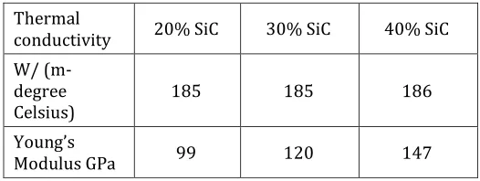
Thermal
conductivity 20% SiC 30% SiC 40% SiC W/ (m-
degree
Celsius) 185 185 186
Young’s
© 2018, IRJET | Impact Factor value: 6.171 | ISO 9001:2008 Certified Journal | Page 2151 The force thus developed helps to stop or slow down the
[image:2.596.313.543.122.247.2]motion of the vehicle. The image given below depicts about the drum brakes which uses hydraulic force for its working.
Fig.1 Hydraulic Drum brake System
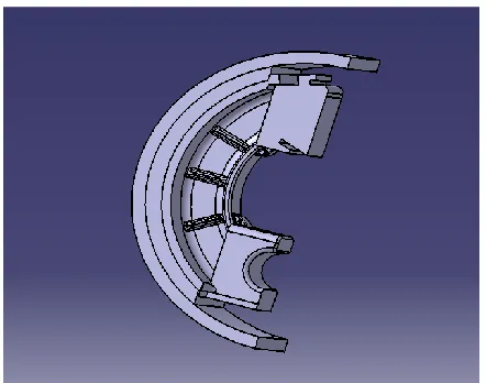
IV. Designing of Drum Brakes
The designing process was done using the Creo Parametric 2.0 designing software. The basic tools that were used was extrude, round, sketch, pattern, mirror etc.The brake shoe model that was designed and the basic brake lining model are depicted below.
Fig.2 Sectional Drum Brake
The model consists of outer wheel drum of 210 mm diameter and the thickness of the brake pad is 12 mm. The brake pad should be replaced when it reaches to 4 mm during its operation. The model is to be analyzed in its static condition. Hence the design is done considering the fact that the brake pad material is in contact with the wheel drum. The different types of forces that act on this brake shoe are the normal reaction acting at the center, moment force acting opposite to the rotating motion of the wheel drum, pressure force acting on the wheel drum due to its contact with the brake pad and the frictional force
[image:2.596.44.285.137.314.2]acting at the contact surfaces. The below shown figure is the generalized brake shoe model with the brake lining material at its both ends.
Fig.3 Brake shoe lining
The brake shoe, brake pad and the wheel drum are designed as different part files in Creo. Later the assembly file is created by assembling these part files. This process is done because assigning the materials would be easier in workbench if the file is an assembled one.
V. Force calculation
Diameter D= 210 mm Speed in rpm N= 3000 rpm
Horse Power= 130 HP w= (2πN) /60
w= 314.16 radian / sec Power= 130*76.04 (kg*m)/sec
= 130*76.04*9.81(N*m/sec)
Power= 95.64 KW (For four wheels) Power= 23.91 KW (For one wheel)
Power = Torque * angular velocity 23911.875 = T * 314.16
Torque T = 76.10 Nm
Consider the force acting on the spring as
T= * a = T/a, = 634N
*a = *(a/2)
* 0.12 = * 0.06
= 1268 N
µ
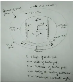
[image:2.596.54.275.434.608.2]
© 2018, IRJET | Impact Factor value: 6.171 | ISO 9001:2008 Certified Journal | Page 2152 Fig.4 Pressure distribution diagram
Pressure calculation
(2πr) /360▫ = a / θ
(2π* 105) /360 degree= a/ 90 degree
a= 157.08 mm a= 0.157 m
Area = length * width =0.157 * 0.09
Area = 0.0141
Pressure= / area Pressure = 89.92 KN/
Heat distribution Q= KA ( /t
23911.875 = 185 * 0.0141 *( - 60) / 0.012
= 170 degree Celsius
VI. Structural Analysis
The design which was modeled is saved in IGES format. This is done to export the file to any other design or analysis software. The model could be exported either as a solid or as a surface model. But in this case the model is exported as a solid model. The Ansys Workbench is opened and in that we need to assign the material to the parts like brake shoe, brake pad and to the wheel drum.
Initially static structural analysis is to be done. So that is chosen and in that engineering model option is used. In this, new materials could be added with their properties or the default standard material could be used in the operation.
In our case, the composite material should be added to the database and their properties should be mentioned properly to get the exact output. The properties which are generally specified are density, Poisson’s ratio, Young’s modulus, tensile strength, compressive strength. After providing these inputs, the material is added to the project. The standard materials like gray cast iron and Aluminum are also chosen. But these materials have their default input values. In the second step the geometry file need to be imported. In the file geometry option, import file option is chosen. This opens a new window from where the model file is browsed and it is then imported to the workbench.
The third step is to open the model option, which takes to the new window. The file which was imported appears in the window. This model must be assigned with the suitable materials. In this case, the brake shoe lining is provided with the composite material and the wheel drum is provided with aluminum alloy and the brake shoe is assigned with gray cast iron. After the assignment of materials, the model is meshed. The sizing of the meshing is made very fine so that the results are very accurate. After the meshing is done, the forces acting on the brake shoe must be provided. This is based on the calculation that was done earlier. There are different types of forces like pressure force, normal reaction, frictional force and also a fixed or displacement motion must be provided.
After assigning the forces by selecting the geometry, the values are provided to it. The direction and magnitude is provided in accordance to the conditions specified. The final step is to obtain the output solution based on the forces applied on the geometry. The different results that are obtained are deformation equivalent stress and equivalent strain. After choosing the different outputs the solve option is chosen. This solves the given condition and provides with the outputs that were mentioned. Thus the structural analysis of the brake shoe and its lining was done using the composite material. This solution obtained needs to be compared with the existing brake shoe lining material’s results. If the results obtained are more
efficient than the existing one, then this composite could be used as the alternative brake shoe lining material.The results for the structural analysis of the brake lining material using composite material are provided below. Also the comparison with the standard material (Asbestos) is provided below.
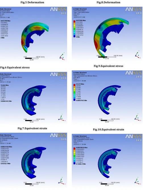
Case1: Al 6061 T6 80%
© 2018, IRJET | Impact Factor value: 6.171 | ISO 9001:2008 Certified Journal | Page 2153 Fig.5 Deformation
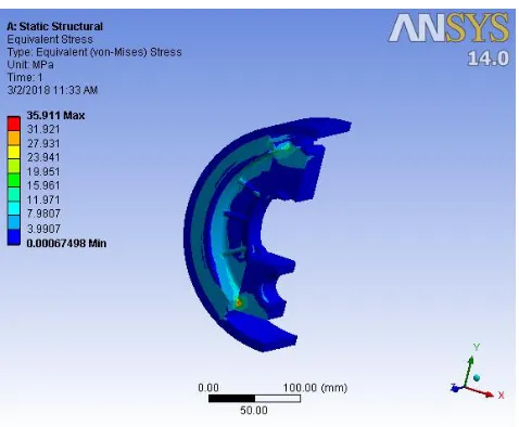
Fig.6 Equivalent stress
Fig.7.Equivalent strain
Case2: Al 6061 T6 70%, Silicon carbide (SiC) 30%
Fig.8.Deformation
[image:4.596.49.552.75.745.2]Fig.9.Equivalent stress
Fig.10.Equivalent strain
[image:4.596.34.553.539.741.2]© 2018, IRJET | Impact Factor value: 6.171 | ISO 9001:2008 Certified Journal | Page 2154 Fig.11.Deformation
Fig.12.Equivalent stress
Fig.13.Equivalent strain
VII. Results & Discussion
Table3.Comparision between Asbestos and SiC
Asbestos SiC 20% SiC 30%
Deformation
(mm) Max 0.01252 Min 0
Max 0.01219 Min 0
Max 0.01330 Min 0 Equivalent
Stress (MPa)
Max 35.911 Min 0
Max 33.664 Min 0
Max 32.221 Min 0
Equivalent strain (No unit)
Max 0.00033 Min 9.50
Max 0.00031 Min 8.94
Max 0.00029 Min 8.14
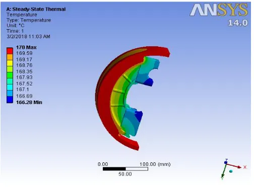
Thermal Analysis:
Thermal analysis follows the similar steps followed in the static structural analysis. The major difference is that it takes into consideration the heat flow in it. Similarly in the engineering model option, the new composite material is added. In this the thermal conductivity of the material is specified. Then the model is imported from the external source and then it enters to the model setup as done during the static analysis. The model is meshed and also the suitable materials are assigned to the individual components like brake shoe, brake lining and the wheel drum. Then the thermal conditions are specified. The initial temperature is specified and then the temperature during the analysis is mentioned. There are different modes of heat transfer like conduction, convection and radiation. In our condition, the heat transfer occurs due to the conduction process and also the heat flow occurs. The maximum temperature attained by the wheel drum during the braking process was calculated earlier. Thus the temperature is applied as per the boundary conditions and the solution could be obtained. The temperature distribution could be analyzed by using the temperature option in the solution command.
Case1: Al 6061 T6 80%
© 2018, IRJET | Impact Factor value: 6.171 | ISO 9001:2008 Certified Journal | Page 2155 Fig.14.Temperature
Case2: Al 6061 T6 70%
[image:6.596.36.288.97.283.2]Silicon carbide 30%
Fig.15.Temperature
Case3: Existing material Asbestos
Fig.16.Temperature
Table.4. Comparison of Temperature for SiC & Asbestos
Temperature (Degree Celsius)
SiC 20 %
SiC 30%
Asbestos
Maximum 170 170 170
Minimum 166.28 166.28 153.52
Since the thermal conductivity of the composite is same at both the compositions of silicon carbide the output solution is also the same.
IX. CONCLUSION
From the above experimental work, the composite was analyzed by using it as the brake shoe lining material. The output results were obtained and after its analysis, it is understood that by using Al 6061 T6- silicon carbide composite, the deformation produced in the material has reduced. Also the stress acting on the component has reduced from 35 Mpa to 32 Mpa. The strain on the component has reduced in a very amount. The static structural analysis has provided with good desired output. Then the thermal analysis is taken into consideration. The temperature distribution in the material has slightly risen when compared with the existing material. There is a rise in temperature from 153 to 165 degree Celsius. Thus this factor must be taken into consideration. The composite material must be added with another material of lighter proportion which could increase the cooling effect of the material. It must possess a property that it acts a cooling medium to the material and the component. Materials like zirconium oxide might serve as a solution to this effect. If it is added to this composite in suitable proportions, then it might turn out to be the perfect solution. Thus from this project the composite material is analyzed and it has both the benefits and drawbacks and a possible solution is also provided to the obtained result.
REFERENCES
[1]. Anup Kumar and R. Saharish Structural and Thermal Analysis of Brake Drum. Middle EastJournal of Scientific Research Vol20. (8). IDOSI Publication. Pp 1012-1016. . 2014.
[2]. Brake Drum Available at an.wikipedia.org/ wiki/ Drum_ brake. Cited March2015.
[3]. Frank Kreith Mechanical Engineering Handle Book Boca Raton: CRC Press LLC. Pp 4-7. 1999.
[image:6.596.35.286.339.529.2]© 2018, IRJET | Impact Factor value: 6.171 | ISO 9001:2008 Certified Journal | Page 2156 [5]. Fred Puhn. Brake Handbook. 2rd edition .HPBooks
Pp4, 15-21. 1985.
[6]. Giri N.K. Automobile Technology. Sixth edition (reprint). Khanna Publisher. Pp 1269-1272.2012.
[7]. James Carvill. Mechanical Engineer’s Data Handbook. First Edition. Butterworth Heinemann Publication. Pp129-131.1993.
[8]. Karim Nice. How Drum Brakes Works. Available at www.howstuffworks.com/autoparts/brake/brake-types/drum-brake 1.htm. cited March 2015
[9]. Kicreyco Brake Drum Catalog. Kic Holding IncPp 1-12. Available at www.kic-group.com. Cited April 2015.
[10]. Blau PJ, McLaughlin JC. “effect of water films and sliding speed on the frictional behavior of truck disc brake materials” international journal of Tribology: Vol 36, 709-715, 2003.
[11]. Liew KW, El-Tayeb NSM. “The effect of rotor disc material on tribo-behavior of automotive brake pad materials.” Surf Rev,625–633,2008.
[12]. Bijwe J., Nidhi and Satapathy B.K., “Influence of amount of resin on fade and recovery behavior of non- asbestos organic (NAO) friction material” International journal of Wear, 1068- 1078, 2005.
[13]. Cho Min Hyung, Kim Seong Jin, Kim Dachwan, Jang Ho, “Effect of ingredients on tribological characteristics of a brake lining: an experimental study” International journal of Wear, 1682-1687 , 2005.
[14]. Mutlu I., Eidogan O., Findik F., “ Production of ceramic additive automotive brake lining and investigation of its braking characteristics” International journal of Tribology, 84-92, 2005.