© 2018, IRJET | Impact Factor value: 6.171 | ISO 9001:2008 Certified Journal | Page 731
power flow controller, the common dc connect is dispensed with amongst series and shunt converter and numerous single phase converters are utilized as a part of place of high evaluations three phase converter. The DPFC controls the line impedances, voltage of bus and impedance of line. It is more solid and lower expensive than the UPFC.
Key Words – DPFC, FACTS, Harmonics, Power quality, UPFC.
1. INTRODUCTION
Primary issues are power quality for some organizations [1].It is an arrangement of limits that enables electrical equipment to work appropriately with no loss [2].According to the customers, Power quality is characterized as any issues have been happened in voltage, current and frequency that makes the power failures [3].For refining the power quality, Facts devices and, custom power devices have been utilized [4], [5]. FACTS and DVR are custom power gadgets which have been utilized for power quality change .When the beginning of the cumbersome machines, inrush current has been expanded, and switching issues have been happened in grid system. Overvoltage, under voltage and interruptions are found in transmission line [6]. A STATCOM is utilized as a part of transmission line which can control the power and transport voltage where it is associated in line .The STATCOM was called as advanced SVC .STATCOM is a shunt associated device. [7]. The static synchronous series compensator (SSSC) is a series converter which infuses a reactive power in the transmission line. It is likewise utilized for controlling the reactive power. UPFC is mix of a STATCOM and a SSSC [8], associated with common dc connect to permit bidirectional flow of active power between the series output terminals of the SSSC and the shunt output terminals of the STATCOM [9].The UPFC isn't generally utilized , Because of high cost and unwavering quality . The DPFC is controlled like line impedance, transmission angle and bus voltage.
2. CONSTRUCTION OF DISTRIBUTED POWER FLOW CONTROLLER
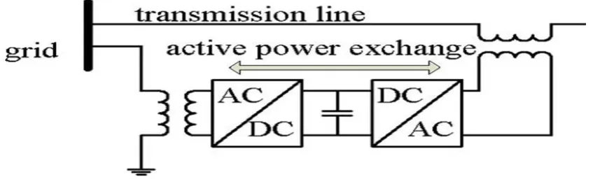
[image:1.595.87.511.553.686.2]In DPFC, shunt and series converters have been utilized which are free to each other. The shunt converter is same as a STATCOM. The DSSC idea, three stage converters are partitioned in to the various single stage converters. In DPFC, Converters are autonomous to each other and dc voltage is given by the self dc capacitor voltage. Arrangement of UPFC Figure 1.
Fig.1UPFC Configuration
3. DISTRIBUTED POWER FLOW CONTROLLER
© 2018, IRJET | Impact Factor value: 6.171 | ISO 9001:2008 Certified Journal | Page 732
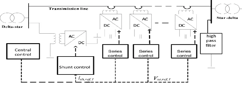
Fig2. DPFC Configuration.
3.1 WORKING OF DISTRIBUTED POWER FLOW CONTROLLER
A. EXCHANCE OF ACTIVE POWER THROUGH REMOVED DC CONNECTION
For exchanging of active power, transmission work as the common dc connection in the middle of series and shunt ac terminals within distributed power flow controller. In this way, it is possible to exchange the active power through the ac terminals.
Fig3.Active power interchange among Distributed power flow controllers.
In this method, fundamental idea is power theory of sinusoidal components. As per the Fourier analysis, a non-sinusoidal current and voltage can be expressed by the sum of non-sinusoidal functions in various frequencies with various amplitudes. Coming about because of the non-sinusoidal voltage and current, the active power is characterized as the mean estimation of the result of voltage and current. Since the integrals of all the cross result of terms with various frequencies are zero, the active power can be expressed by Where Vi and Ii are the voltage and current at the Ith harmonic frequency, respectively, and ∅th is the angle between the voltage and current. Equation (1) clarifies the active power at
various frequencies isdisengaged from other.
(1)
Inside the DPFC, The shunt converters get active power at fundamental frequency from the grid and furthermore infusing the current in grid at a harmonic frequency. . With presumption of a lossless converter, the active power delivered at fundamental frequency is equivalent to the power accepting at the harmonic frequency. Fig.3 demonstrates exchanging the active power between shunt and series a converters.
B. By using 3rd harmonic components in each phase
© 2018, IRJET | Impact Factor value: 6.171 | ISO 9001:2008 Certified Journal | Page 733
Fig.4DPFC control block diagram
There are used three types of controller Shunt, series and central controller.
A .Shunt control
Working of shunt control, infuse the current at constant third harmonic in transmission line. Around then, it ingests active power from the grid at fundamental frequency to remain the capacitor DC voltage of the shunt converter at a constant value and infusing reactive current at the fundamental inside the grid.
B .Series Control
Each single-phase converter has its own series control through the transmission line. The principle utilization of the series controller to keep up its own particular capacitor dc voltage and to create series voltage at the fundamental frequency which is checked by the central control. These controllers have first order low pass filter and third order band pass filter.
C. Central Control
It is produced reference signals for the shunt and series converters of the DPFC. All the reference signals are created at the fundamental frequency as per the framework necessity. It is checked the power flow, power oscillation low frequency damping and asymmetrical components adjusting for the series and shunt converter's reactive current signal.
5. ADVANTAGES OF DPFC OVER UPFC
The DPFC have the merits over the UPFC, which are as follows
(a)High dependability: In DPFC system, the shunt and series converters are autonomous to each other. So when a failure happens in the converter, does not impact other converters.
(b)High control ability: The DPFC likewise control every one of the parameters of power system, for example, line impedance, transmission angle, and bus voltage magnitude.
(c)Low Cost: The DPFC, its cost is low in contrast with UPFC in light of lower rating single phase converters are utilized as a part of place three phase converter.
6. SIMULATION & RESULT OF DPFC
[image:3.595.89.508.168.325.2]© 2018, IRJET | Impact Factor value: 6.171 | ISO 9001:2008 Certified Journal | Page 734
Fig.5: A simulation model of DPFC for voltage sag and swell mitigation
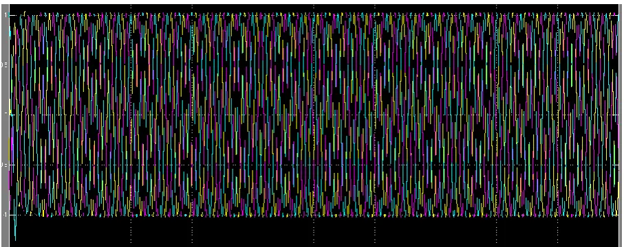
As shown in Fig. is simulated the performance of DPFC, The three phase fault has been occurred close the load. The time period of fault is 0.5-0.7 second’s. As shown in Fig.5 (a), a voltage sag is received, when fault is happened lacking DPFC. When added the DPFC, voltage sag is mitigated, as shown in Fig.5 (b).
Fig.5 (a) Three phase voltage sag waveform analysis without Distributed power flow controller
[image:4.595.85.524.87.268.2] [image:4.595.71.523.345.526.2] [image:4.595.71.525.555.735.2]© 2018, IRJET | Impact Factor value: 6.171 | ISO 9001:2008 Certified Journal | Page 735
Fig.5(c) Three-phase load current swell waveform analysis without Distributed power flow controller
Fig.5 (d) Modification of three-phase load current swell using Distributed power flow controller
[image:5.595.74.522.105.291.2] [image:5.595.73.526.327.501.2] [image:5.595.88.509.531.744.2]© 2018, IRJET | Impact Factor value: 6.171 | ISO 9001:2008 Certified Journal | Page 736
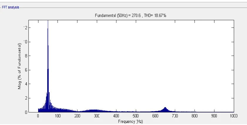
Fig.5 (f) Total Harmonic distortion (THD) analysis of load voltage with Distributed power flow controller
7. CONCLUSION
In this paper has been spoken to various thought known as DPFC. The joint dc link connect among the shunt and series converters arrangement converters, which is utilized for exchanging active power inside UPFC, has been evacuated. The power has been exchanged through the transmission line at the third harmonic frequencies. What's more, three converters is supplanted by utilizing the numerous single stage converters. The trustworthiness of the DPFC is imperatively enhanced due to the end of the three arrangement converters. Accordingly, DPFC gives a reasonable demonstration in power quality change and power flow control.
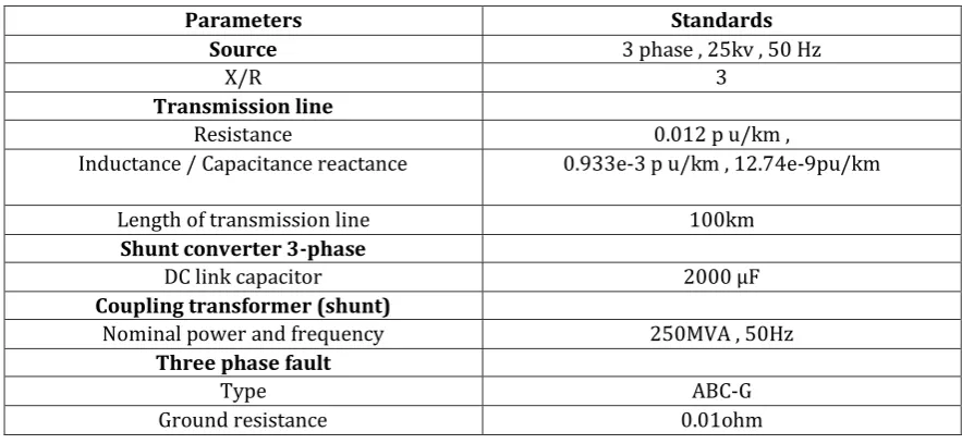
[image:6.595.69.524.55.301.2]APPENDIX
TABLE I. Simulation Parameters
Parameters Standards
Source 3 phase , 25kv , 50 Hz
X/R 3
Transmission line
Resistance 0.012 p u/km ,
Inductance / Capacitance reactance 0.933e-3 p u/km , 12.74e-9pu/km
Length of transmission line 100km
Shunt converter 3-phase
DC link capacitor 2000 F
Coupling transformer (shunt)
Nominal power and frequency 250MVA , 50Hz
Three phase fault
Type ABC-G
Ground resistance 0.01ohm
8. REFERENCES
[1] S. Masoud Barakati, Arash Khoshkbar Sadigh and Ehsan Mokhtarpour, “Voltage Sag and Swell Compensation with DVR Based on Asymmetrical Cascade Multicell Converter”, North American Power Symposium (NAPS), pp.1 – 7, 2011
[image:6.595.76.518.478.682.2]© 2018, IRJET | Impact Factor value: 6.171 | ISO 9001:2008 Certified Journal | Page 737
[7] N. G. Hingorani, L. Gyugyi, “Understanding FACTS: Concepts and Technology of Flexible AC Transmission Systems,” IEEE Press, 2000.
[8] K.K. Sen, 1998, “SSSC – Static Synchronous Series Compensator: Theory, Modeling and Application”, IEEE Trans. on Power Delivery, 13(1), pp. 241-246.
[9] A.-A. Edris, “Proposed terms and definitions for flexible ac transmission system (facts),” IEEE Trans. Power Del., vol. 12, no. 4, pp. 1848–1853, Oct. 1997.