© 2017, IRJET | Impact Factor value: 5.181 | ISO 9001:2008 Certified Journal
| Page 298
Performance & Application Based Comparative Analysis of Emerging
Technologies in Energy Storing Devices & Systems in Smart Grid
Vishal Bhosale
#1, Vivek Saxena
*2#-1Student, Department of Electrical Engineeirng, SKNSITS Lonavala, Maharashtra India
#-2Assistant Professor, Department of Electrical Engineeirng, SKNSITS Lonavala, Maharashtra India
---******---Abstract — Utilizing renewable energy sources for
production of electrical energy is need of hour to meet the ever-increasing demand of electrical energy. With the emerging smart grid, these sources have become an integral part of the system known as microgrid. Installation of microgrid system is proving beneficial to both the user and electricity utility provider. Microgrids offers various advantages, which includes better power factor, reduction in environment pollution and global warming by utilizing low carbon technology. Microgrid consists non-conventional energy sources for generation of electrical energy, transmission system, its protection system and energy storage systems.
Storage systems stores surplus electrical energy that acts as the buffer & utilized at the time of need. Storage systems are pivotal in various applications such as peak shaving, electrical vehicles, and integration of electrical vehicles to the grid etc. This paper discusses the comparative analysis based on performance & applications of various electrical energy storage systems used in microgrid.
Keywords — Storage systems, Micro grid, Electric vehicle, Fuel cell, PHES, Flywheel, Batteries
I. INTRODUCTION
The non-renewable natural resources of energy are depleting at faster rate with rapidly increasing demand for electrical energy. The production of electrical energy using such sources leads to production of greenhouse gases that are contributing in global warming apart from polluting the environment. It is time to shift our attention to explore various renewable energy generation schemes in an order to make the energy proof future & reducing the carbon emission. With the advancements in technology, it has become easy to provide electrical energy to remote locations not connected to grid otherwise. The renewable energy generating systems ranges from simple systems such as generation through PV system to advance wind turbine systems.
For the efficient generation, transmission & utilization of electrical energy the existing grid system is upgrading with extensive use of information sharing on real time basis. The integration of renewable energy sources with
the existing grid for the production of electrical energy had leaded to evolution of new concept known as
Microgrid. The microgrid constitutes of systems for
production, transmission & utilization of electrical in small premises. In other words, it is the replica of main grid shrink over small geographical area. Energy storage systems (ESS) are the integral part of the microgrid. Energy Storage systems supplies excess power during peak hours and reduces the use of fuel consumption used by diesel generators etc.
There are a various types of storage technologies used today. The storage technologies may be classified as Direct Storage Systems & Indirect Storage System. Direct storage systems consists of electrical or magnetic storage systems while indirect methods uses mechanical or chemical energy storage types.
II. NEEDOFSTORAGESYSTEMS As discussed the energy storage systems are used to store electrical energy in some form of energy and supplies it whenever it is required. The renewable energy sources are spread over wide geographical area & the production of electrical energy using these resources if intermittent in nature. ESS are used to integrate with renewable energy sources because the renewable sources such as availability of sun & wind are intermittent in nature. In such situation, it becomes important to improve reliability and stability of the system with continuous supply of electrical energy. The solution to these problems lies in the integration of energy storage systems with microgrids.
© 2017, IRJET | Impact Factor value: 5.181 | ISO 9001:2008 Certified Journal
| Page 299
Such changes in the system and control of grid calls smart, efficient power transmission and distribution networks. It is required to manage storage of energy at appropriate time, location or both to manage generation with consumption and to improve grid stability.
III. TYPESOFSTORAGESYSTEM
There are numerous technologies employed for storing surplus electrical energy. These technologies can be classified based on domain in which this energy is stored. It can be categorized into mechanical (pumped hydroelectric storage, compressed air storage and flywheels), electrochemical storage (rechargeable batteries and flow batteries, electrical (capacitors, super capacitors and superconducting magnetic energy storage),
thermochemical storages (solar fuels), chemical (hydrogen
fuel cells) and thermal energy storage (sensible and latent heat storage).
IV. DESCRIPTION OF VARIOUS
STORAGE SYSTEMS
A] Mechanical storage systems
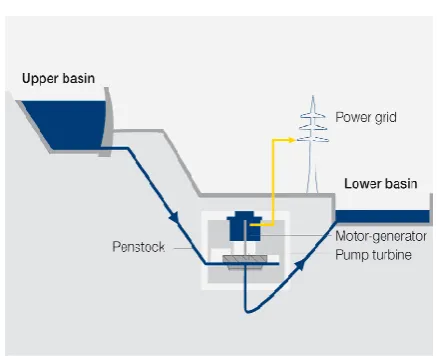
1) Pumped hydroelectric
storage-Pumped Hydro Energy Storage (PHES) system is the economical method for storing large amounts of electrical energy. Figure 1 shows the block diagram of a PHES. The system consists of two reservoirs (Upper & Lower). The working of PHES system can be classified into two modes:
1. Generating Mode: The water is stored in upper reservoir is allowed to fall on turbine through conduits The potential energy of the water converts into kinetic energy & drives the turbine. This turbine is connected to generator that converts the mechanical energy into electrical energy. The electrical energy so generated is fed into the electricity grid.
2. Pumping Mode: Unlike other hydro power plants, the water is not drained, the water is stored in a lower reservoir. In the low demand duration when the generation of electricity is economical, the water is again raised to the upper reservoir with the help of pump coupled to electric motor. Therefore, in the pumping mode the PHES acts as load to the electricity system.
Fig (1)-PHES
2) Compressed Air Storage-
In this storage system the air is compressed to high pressures (70 to 100+ Bar) and then it is injected into either an underground tanks (e.g. cavern) or an above ground system of tanks. For generating electricity, the gas is mixed with a fuel (e.g. natural gas), burned and expanded through gas turbine which runs a generator. The generator generates electricity and supply during peak hours to the grid.
Fig (2)-CAES
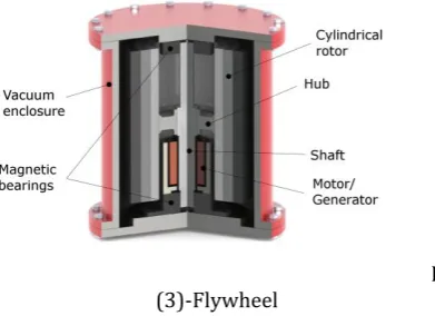
3) Flywheel
system-This system consists of following key components: i. Flywheel, bearings,
ii. Reversible motor/generator, iii. Power electronic device and iv. Vacuum chamber.
[image:2.595.320.539.92.270.2] [image:2.595.324.570.434.585.2]© 2017, IRJET | Impact Factor value: 5.181 | ISO 9001:2008 Certified Journal
| Page 300
Fig (3)-Flywheel
B]Battery storage systems
(Electrochemical)-The rechargeable battery also known as secondary cells are most commonly used energy storage systems. Each cell constitutes of following components:
i. Positive Electrode: Anode ii. Negative Electrode: Cathode
iii. An electrolyte that can be liquid and solid. A cell can convert energy bi-directionally i.e. from chemical to electrical & electrical to chemical.
1) Lead-acid
battery-It is the rechargeable battery, which consists of the cathode made of PbO2, anode made of Pb, and the electrolyte is made up of sulphuric acid. Lead acid batteries offers fast response times, relatively high cycle efficiencies (63-90%) and low capital cost. The only disadvantage is that they have relatively they have low cycling times.
2) Lithium –ion (li-ion)
batteries-In a Li-ion battery, the cathode is made up of lithium metal oxide such as LiCoO2 and LiMO2, and the anode is
made of graphite carbon. The electrolyte is LiClO4. They
have high efficiency upto 97% but have less lifetime and higher cost.
3) Sodium-sulphur (Na-S) batteries-
A sodium sulphur battery utilizes molten sodium and molten sulphur as two electrodes and employs beta alumina as the solid electrolyte. These batteries have low manufacturing cost but high operating cost. These batteries are capable of operating at high temperature.
4) Flow battery energy
storage-Fuel cells contains one or more dissolved electroactive species that flows through a cell & reversibly converts chemical energy to electrical energy. In the charging phase, one electrolyte is oxidised at the anode and while other electrolyte is reduced at the cathode and the electrical energy is converted to chemical energy. These batteries have high capacity, low discharge. However, the
disadvantage is they have low density, high complexity and low performance. Fig (4) shows flow battery.
Fig (4)-Flow battery
C] Electrical Storage Systems
1) Capacitor and Super Capacitor-
A capacitor consists of two metal conductors separated by a thin layer of dielectric material (ceramic, glass). The capacitor stores the electrical energy in form of electric field. They offers high power density and shorter charging time compared to conventional batteries.
Supercapacitors also known as electric double layer capacitors or ultracapacitors contain two conductor electrodes, an electrolyte and a porous membrane separator. Due to their structures, supercapacitors can have both characteristics of capacitor and electrochemical batteries.
2) Superconducting Magnetic Energy Storage It contains of three main components: i. Superconducting coil unit ii. Power conditioning subsystem iii. Refrigeration and vacuum system.
This system stores electrical energy in form of the magnetic field generated by Direct Current (DC) in superconducting coil. The superconducting material at superconducting state stores electrical energy at nearly no losses. They have high power density, fast response time, high efficiency and long life. These storage systems have high capital cost and negative environmental impact due to stromg magnetic field.
D] Thermochemical batteries 1) Solar fuels –
Solar fuel is the latest technology employed for storing energy. To produce solar cells, include:
a) Natural Photosynthesis b) Artificial Photosynthesis c) Thermochemical approaches
[image:3.595.60.256.115.257.2]© 2017, IRJET | Impact Factor value: 5.181 | ISO 9001:2008 Certified Journal
| Page 301
thermochemical method uses thermal processes for solar fuels production, which requires very high temperature to split water into its constituents. Solar fuel technology is in developing stage. The major drawback of artificial photosynthesis is that the water splitting catalysts are usually expensive elements & it requires large area to concentrate sunlight.
E] Chemical storage
Hydrogen storage- This system uses two separate
processes for storing energy and producing electricity. The use of water electrolysis unit is common way to produce hydrogen, which can be stored in high-pressure containers. Fuel cells can convert chemical energy into hydrogen and oxygen to electricity. These cells are quieter, produce less pollution and energy efficient.
F] Thermal energy storage
Thermoelectric energy storage (TEES) for solar thermal power plants consists of a molten salt. Solar thermal power plants to give continuous power output irrespective of day & night collect the heat.
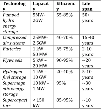
V. COMPARISONBETWEENVARIOUSSTORAGE SYSTEMS
Technolog
y Capacity Efficiency Life span
Pumped hydro energy storage
5MW-2GW 55-85% 50+ years
Compressed
air systems 25MW-2.5GW 40-70% 15-40 years
Batteries 1 kW –
50 MW 65-75% 2-10 years
Flywheels 5 kW –
20 MW 90-95% ~20 years Hydrogen
fuel storage 1 kW – 10 GW 20-40% 5-10 years Supermagn
etic energy storage
10 kW –
1 MW 95% ~30 years
Supercapaci
tors < 150 kW 85-95% ~10 years
Table (1) – Comparison between energy storage systems
Technology Cost/kw Life cycles
Pumped hydro
energy storage 2500–4300 10,000–30,000
Compressed air
systems 400–800 8000–12,000
Lead-acid 300–600 500–1000
Li-ion 1200–4000 1000–10,000
NaS 1000–3000 2500–
43002500– 4500
Flywheels 250–350 20,000+
Hydrogen fuel
storage 500 1000+
Supermagnetic
energy storage 200–300 20,000+
Supercapacitors 100–300 100,000+
Table (2) - Cost and cycles of energy storage systems
VI. CONCLUSIONS
Storage systems are important component of smart grid that enables to store electrical energy, which can be used to manage demand during peak hours and other emergencies. In this research paper, a comparative study has been conducted on various types of technologies emerging in storage systems used in smart grid. In the analysis it has been found that hydro electric energy storage system has a higher energy storage level, longer life span and operating at higher efficiency but at the same time it has a high installation cost.
The battery storage systems are less costly as compared to hydroelectric and compressed air systems but it have a lesser life span of about 2-10 years, which is very less as compared to other types.
Super capacitors energy storage systems have the lowest installation cost, have high life cycles operating with high efficiency but have less capacity.
Various battery systems such as lead acid, Lithium ion or NaS battery has good life cycles with low initial cost. Hence, the battery systems are affordable, good efficiency and high life span.
REFERENCES
[1] Review on microgrid technology Hartono BS,Budiyanto
Faculty of Engineering,University,
Indonesia Depok 16424,[email protected] [2] Battery energy storage technology for power
systems—An overview K.C. Divya∗,1, Jacob Østergaard1 Technical University of Denmark, Kgs. Lyngby 2800, Denmark
[image:4.595.28.242.428.659.2]