International Journal of Emerging Technology and Advanced Engineering
Website: www.ijetae.com (ISSN 2250-2459,ISO 9001:2008 Certified Journal, Volume 5, Issue 10, October 2015)
334
Simulation and Experimental Analysis of Mechanical Crosstalk
in an Ultrasonic Matrix Array
Pedro Acevedo Contla
1, Israel Sanchez Domínguez
21Universidad Nacional Autonoma de Mexico, Instituto de Investigaciones en Matematicas Aplicadas y en Sistemas, Apdo.
Postal 20-726 Admon. No. 20, 01000 Mexico D.F., Mexico
2Universidad Nacional Autonoma de Mexico, Instituto de Investigaciones en Matemáticas Aplicadas y en Sistemas Unidad
Merida, Av. Colon # 503-F x Av. Reforma y Calle 62-A, Centro C.P. 97000, Merida, Yucatan, Mexico.
Abstract— The phenomenon known as mechanical crosstalk from the point of view of its physical nature and the causes of its generation are analyzed. It is also analyzed how it may affect the performance of ultrasonic matrix arrays. This phenomenon occurs primarily in matrix arrays and it is magnified by certain factors causing serious problems in the performance of this type of transducers. This work includes simulations of the mechanical crosstalk phenomenon using the Finite Element Method (FEM), and describes the construction of a 2 x 3 matrix array. The analysis includes the effect of the mechanical crosstalk in the radiation pattern emitted by the ultrasonic array.
Keywords— Ultrasound, Matrix array, Mechanical crosstalk, Piezoelectric ceramic, Finite Element Method.
I. INTRODUCTION
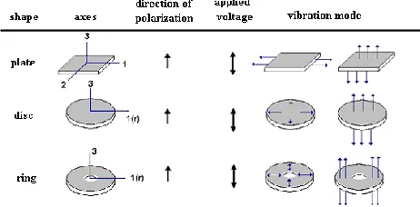
[image:1.612.332.563.260.374.2]At present the development of new piezoelectric materials and electronics have led the processes of design and construction of transducers towards miniaturization. This miniaturization process causes changes in the performance of ultrasonic transducers, since elements within these transducers are closer. The proximity between the elements of the transducer produces a phenomenon which directly affects performance; this phenomenon can alter the physical properties of the piezoelectric materials used in the construction of this type of transducers, mainly in their vibration mode [1] [2]. The phenomenon analyzed in this work is known as mechanical interference or crosstalk [3] [4]. Crosstalk can be defined as the not desired interaction between the elements of the array, where the separation between elements, in some cases it is in the order of millimeters or microns [5] [6], this generates interference between the different vibration modes, as shown in Figure 1 (mainly in the lateral vibration mode). This phenomenon may be due to the ineffective isolation between piezoelectric elements in the array, or by capacitive effects between piezoelectric elements.
Figure 1. Vibration modes of a piezoelectric ceramic according to its geometry.
Figure 2 shows which are the main factors that cause the electrical and mechanical interference, in this analysis only the mechanical interference is taken into account (mechanical crosstalk) [7] [8].
[image:1.612.334.553.566.686.2]The analysis of the crosstalk phenomenon is important since this phenomenon directly affects the performance of the transducer [9] [10], and the ability to control the radiation beam, either in transmission or reception, it also can cause attenuation in the main lobe of radiation, or even generate unwanted signals (spurious signals) [11] [12]. For medical applications, this phenomenon induces errors in diagnosis since there is not a "calibrated" device for comparison [13].
International Journal of Emerging Technology and Advanced Engineering
Website: www.ijetae.com (ISSN 2250-2459,ISO 9001:2008 Certified Journal, Volume 5, Issue 10, October 2015)
335
II. METHODOLOGY
Simulations were made to determine the presence of crosstalk in a piezoelectric array. However, the methodologies to deal with a qualitative or quantitative form of the crosstalk effect in a transducer performance are still limited. A comparison between a simulation based on the Finite Element Method and experimental measurements was made in order to provide a methodology capable of providing quantitative values for mechanical crosstalk and to determine how this phenomenon affects the transducer performance. Mechanical crosstalk is generated by several sources [14] [15], one of these sources is the lateral vibration mode, proximity between the piezoelectric elements is another factor that contributes [16], the geometry of the elements in the array can also be a factor for a significant increase in the crosstalk phenomenon, e.g. square ceramics present a larger contact area than circular ceramics in an array.
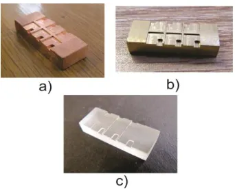
To observe and quantify the crosstalk phenomenon on an experimental basis a 2 x 3 matrix array was constructed, this array is shown in Figure 3. Different array configurations were used to observe the presence of crosstalk and to observe if this phenomenon increases for a particular configuration [20] [21]. In a matrix where piezoelectric elements are separated by a distance λ / 4, and λ is defined by the following equation:
(1)
where λ is the wavelength, c is the speed of ultrasound
[image:2.612.325.564.314.397.2]and f is the oscillation frequency.
Figure 3. Photograph of the experimental array constructed using piezoelectric ceramics
Considerations on the increase of the distances between the elements for different configurations depended on the number of ceramics used in each array, since for some configurations piezoelectric ceramics were not placed side by side but there was a space between them producing a larger distance between each element of the array.
Figure 4 shows the dimensions of the matrix array and the distribution of the piezoelectric ceramics [22].
In the array shown in figure 4 only one piezoelectric ceramic was excited at the time using a pulse, the output voltage of the remaining ceramics was measured in order to detect any energy interaction between the elements showing the probable presence of mechanical crosstalk, the output voltage signal was observed using a digital oscilloscope as shown in figure 5.
[image:2.612.327.557.431.510.2]Figure 4 Diagram of the array constructed for the measurement of crosstalk
Figure 5. Diagram of the experimental array.
[image:2.612.83.254.517.655.2]International Journal of Emerging Technology and Advanced Engineering
Website: www.ijetae.com (ISSN 2250-2459,ISO 9001:2008 Certified Journal, Volume 5, Issue 10, October 2015)
336
TABLE I
PHYSICAL PROPERTIES OF PIEZOELECTRIC CERAMICS PIC255
Density [Kg/m3] 7800
Young´s module [N/m2] 1X10¹¹
Radio Poisson 0.34
Coefficient of thermal expansion [1/K]
-5x10⁻⁶
As already mentioned the crosstalk effect present in an ultrasonic array is due to different factors such as:
Dimension and geometry of the piezoelectric
ceramics
Distance between elements
Oscillation frequency
these factors affect the response of the array; using the simulated and the experimental results different radiation patterns were obtained, they are shown in figure 9. Crosstalk was increased in order to observe how this phenomenon affects the shape in each case [28].
III. RESULTS
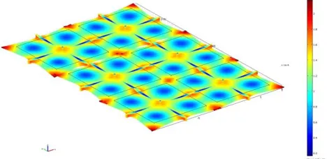
Simulated results using the FEM showed that the greater is the number of elements the greater is the crosstalk effect as shown in Figure 6, in this case the response of the simulation of an array with square geometry ceramics showed that there is greater interaction of energy in the region where the proximity between the elements is greater, based on these results it is possible to say that the geometry is an important factor in the crosstalk phenomenon, it has a greater effect in areas where proximity is greater.
[image:3.612.64.274.155.214.2]Analyzing the experimental results in the array constructed using square ceramics; it was found that there is crosstalk between elements due to the proximity and geometry of these elements.
Figure 6. Simulation of a 2 x 3 elements array.
[image:3.612.336.559.242.385.2]Figure 7 shows the crosstalk effect in the experimental array. Figure 8 show that the crosstalk phenomenon causes changes in the natural frequency of oscillation producing harmonics that may greatly affect the performance of the transducer. This is one of the problems that commonly arise in piezoelectric arrays, reason why study them is important to provide solutions to help to minimize the effect caused by the crosstalk phenomenon.
Figure 7. Experimental Measurement of crosstalk.
Figure 8. Crosstalk effect at the natural frequency of oscillation.
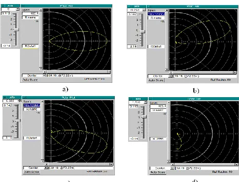
Finally, based on the overall results radiation diagrams were obtained to show that, indeed, the crosstalk phenomenon may change the radiation pattern, causing the deflection of the radiation beam in directions different from the ideal. Figure 9 shows the radiation patterns with and without the crosstalk phenomenon.
[image:3.612.324.566.417.540.2] [image:3.612.50.284.545.659.2]International Journal of Emerging Technology and Advanced Engineering
Website: www.ijetae.com (ISSN 2250-2459,ISO 9001:2008 Certified Journal, Volume 5, Issue 10, October 2015)
337
[image:4.612.51.284.241.419.2]Figures 9b, 9c and 9d show that depending on the intensity of the crosstalk the radiation pattern is more or less distorted or even dimed leading to an error in the performance of the transducer. In all cases the value of crosstalk was modified both in sign and intensity. The sign affects the direction of the radiation pattern. Figure 9d shows how the intensity of crosstalk causes a strong attenuation and a change of direction in the beam; the presence of harmonics it is also observed [29].
Figure 9. Radiation patterns of the array without (ideal condition) and with different crosstalk levels.
IV. CONCLUSIONS
Simulated and experimental results of ultrasonic matrix arrays using piezoelectric ceramics with square geometry and different numbers of elements were obtained in order
to analyze the crosstalk phenomenon. It was observed in all
cases the presence of this phenomenon which is magnified in accordance with the geometry and number of elements of the array.
An important conclusion is that in all cases, the presence of crosstalk is due to the lateral vibration mode since in this vibration mode the interaction of energy between the elements was at its maximum level. Results also showed that crosstalk may be able to cause changes in the natural frequency of oscillation and generate harmonics which are capable of modifying the radiation pattern and the central frequency of the ultrasonic transducer array.
For all these reasons the study of the crosstalk phenomenon is very important. To minimize or even eliminate this phenomenon would ensure that the error in the design and construction of ultrasonic transducer arrays could be reduced guaranteeing a better performance of this type of transducers.
Acknowledgements
The authors thank DGAPA PAPIIT-IN109513 and IT101213 for its support. P. Acevedo thanks the support of
Prof. Piero Tortoli, Dipartimento di Ingegneria
Dell’Informazione, Universitá Degli Studi Firenze, Italy.
REFERENCES
[1] T. A. Whittingham: ―New and future developments in ultrasonic imaging‖ The British Journal of Radiology, Special Issue (1997) pp S119-S132.
[2] G. S. Kino and C. S. Desilets: ―Design of Slotted Transducer Arrays with Matched Backings‖ Ultrasonic Imaging, Vol. 1, (1979) pp 189-209.
[3] G. Caliano, A. Caronti, M. Baruzzi, A. Rubini, A. Iula, R. Caratenuto, M. Pappalardo, ―Pspice modeling of capacitive microfabricated ultrasonic transducers‖, Ultrasonics 40 (2002), Elsevier, pp 449-455.
[4] A.R. Selfridge, G.S. Kino, B.T. Khuri-Yakub, ―Fundamental Concepts in Acoustic Transducer Array Design‖. Ultrasonics Symposium Proceedings, Vol. 2, IEEE 80CH1602-2, (1980), pp. 989 – 993.
[5] W. Frederick, H. Kaarmann, R. Lerch, ―Finite element modeling of acoustic radiation from piezoelectric phased array antennas‖. Ultrasonics Symposium, (1990), pp 763 – 767.
[6] Shung K. Kirk and Zipparo MichaeL, ―Ultrasonic Transducers and Arrays‖, IEEE Engineering in Medicine and Biology (1996), pp 20-30.
[7] D. Berlincourt, ―Piezoelectric crystals and ceramics,‖ in Ultrasonic Transducer Materials, (0. E. Mattiat, Ed. New York, 1971), ch. 3, pp. 74-76.
[8] Li Ding, Pinaki Mazumder, and David Bloouw, ―Crosstalk Noise Estimation Using Efective Coupling Capacitance‖, ISCAS 2002. IEEE International Symposium on Circuits and Systems, (2002), pp V-645 - V-648 vol.5.
[9] John D. Larson ―Non-ideal radiators in phased array transducers‖ Ultrasonics Symposium, (1981), pp. 673 – 684.
[10] B.D. Steinberg: Principles of Aperture and Array Systems Design (John Wiley & Sons, 1976).
[11] K.N. Bates, Acoustical Imaging, Volume 9, Keith Wang editor, Plenum Press, N.Y., (1980).
[12] United States Patent Application Publication, US2005/0033181 A1, (2005).
[13] Kino, G. S., and Baer, R. "Theory for cross-coupling," Proceedings of the IEEE Ultrasonics Symposium, Vol. 2, (1983). pp 1013–1019. [14] D. H., Turnbull and F. S. Foster: "Fabrication and characterization of
transducer elements in two-dimensional arrays for medical ultrasound imaging," IEEE Trans. Ultrason. Ferroelectric. Freq.Control, Vol. 39, No. 4 July (1992), pp 464 – 475.
[15] R. L. Bear and G. S. kino, ―Theory for cross coupling in ultrasonic transducer arrays‖ American Institute of Physics, vol. 44, May 15 (1984), pp. 954-956.
International Journal of Emerging Technology and Advanced Engineering
Website: www.ijetae.com (ISSN 2250-2459,ISO 9001:2008 Certified Journal, Volume 5, Issue 10, October 2015)
338
[17] S. W. Smith, O. T. Von Ramm, M. E. Haran and L. Thurstone Frederick: ―Angular response of piezoelectric elements in phased array ultrasound scanners‖. IEEE Transactions on Sonics and Ultrasonics. Vol. SU-26, No. 3, (1979), pp 185-191.
[18] A. Aulet, C.A. Negreira, H. Gomez, I., A Basora, J. A. Eiras,‖ Identification of lateral vibration modes of piezoelectric composites 1 -3 and their effects‖. IEEE Ultrasonics Symposium, (1994), pp. 1063 – 1066.
[19] D. Certon, F. Patat, O. Casula, L.P. Trans Hu Hue,‖2 Dimensional modeling of lateral modes in 1 – 3 piezocomposites‖ IEEE Ultrasonics Symposium, (1994), pp 991 – 994.
[20] Dominique Certon, Frédéric Patat, Frank Levassort, Guy Feuillard, and Brynjar Karlsson, ―Lateral resonances in 1 – 3 piezoelectric periodic composite: Modeling and experimental results‖. Accoustical Society of America Vol.101, No.4, (1997), pp. 1 – 9. [21] I. Sánchez. MSc. Thesis, ―Metodologia para avaliação do
"cross-talk" em transdutores ultra-sônicos matriciais‖. Universidade Federal do Rio de Janeiro, Brasil, (2003).
[22] B. Jaffe, W. R. Cook and H. Jaffe: ―Piezoelectric Ceramics‖. (Academic Press Inc. ISBN 0-12-379550-8,1971).
[23] Roh Y., Khuri-Yakub B.T., ―Finite Element Modeling of Capacitor Micromachined Ultrasonic Transducers‖ IEEE Ultrasonics Symposium, (2000), pp 905 908.
[24] Nelson Theethayi, Rajeev Thottappillil, Yaqing Liu, Raul Montano, ―Important parameters that influence crosstalk in multiconductor transmissions lines‖. Electric Power Systems Research Volume 77, Issue 8, June, ELSEVIER 2007, Pages 896–909.
[25] Sánchez I, Acevedo P., Moreno E., Von Krüger M., ―Crosstalk effects caused by the geometry of piezoelectric elements in matrix ultrasonic transducers ― Brazilian Journal of Biomedical Engineering, Volume 27, Number 2, pp. 90-97, 2011.
[26] COMSOL 3.3: Manual Structural Mechanics Module pp 323 - 346, V. 3.3, (2006).
[27] http://www.piceramic.com/piezo_materials_2.php.
[28] Yongrae Roh, and Butrus T. Khuri-Yakub, ―Finite Element Analysis of Underwater Capacitor Micromachined Ultrasonic Transducers‖, IEEE Transactions on Ultrasonics, Ferroelectrics, and Frequency Control, vol. 49, no. 3,(2009), pp. 293 -298.