ANALYSIS OF HIGH SPEED SHEAR SLITTING MACHINE BASED ON
CUTTING FORCE, TEMPERATURE AND CUTTING SPEED
N. Ab Wahab, Syed Ahmad Sharif Bin Wan Idrus and Abdul Khahar Bin Nordin
Faculty of Mechanical and Manufacturing Engineering Technology, Universiti Teknikal Malaysia Melaka, Hang Tuah Jaya, Durian Tunggal, Melaka, Malaysia
E-Mail: [email protected]
ABSTRACT
High speed machining is well known in manufacturing world and it is one of the most demanding process in every industry today. Almost every factory in this world using this process in order to make their product better in every aspect. This study is for high speed shear slitting process which is one of the oldest method in shearing process and it will have focused for academic purpose. Although there are many methods such as laser cut, plasma cut and waterjet available but there is some problem occurred such as high cost, maintenance, and chip formation. The new model of high speed shear slitting prototype will be tested by simulation to evaluate cutting forces, temperature and cutting speed. The result is the parameter of the analysis can be analyzed. The conclusion is the shear slitting process can be invented from industry use and can be used for academic purpose.
Keywords: high speed machining, shear slitting, cutting forces, temperature, cutting speed.
INTRODUCTION
High-speed machining (HSM) known as high-speed cutting (HSC) for a given material, is defined as the high cutting speed above which shear localization develops completely in primary shear zone. It is now recognized as one of the key manufacturing technologies for productivity and throughput. HSM found in many industrial field due to development of tougher, more refractory tool materials and HSM spindles. Most of Shear slitting consisted of two circular sharp edges in contact to provide a cutting action like a pair of scissor. Set of this knives are positioned across the sheet using holder that can be precisely set and easily repositioned. It is recommended for films that are thick or though. By shearing the material, the tool is rotated. The relatives speed of the tool and work piece is zero that even the machine rotates in high speed condition, the friction factor can be ignored.
Shear and deformation
In any machining operation there are amount of forces acting on the work piece and it usually created chip due to motion of chip friction and a normal force to support that. At material side thickness of the metal gained while it flows from uncut to cut portion. The rake affects the chip flow. Metal cutting uses a wedge shaped cutting tool to engage the work piece and remove the layer of material in the form of chip. There must have a shear force to support this When the cutting tool engage the work piece, material directly ahead of the tool deforms and relieved some stress by flowing out into space directly above the tool as the tool advance. This occurs in a narrow area extending from the cutting edge to the work surface
Machining performance effect
One of the critical differences on mechanics of cutting between high speed machining and conventional machining is that in high speed machining, a serrated chip is regularly generated which affects almost every aspect of high speed machining process, such as
a) Cutting forces
b) Cutting temperature
c) Chip formation
The parameter of chip formation can be ignored and one other parameter can be analyzing such as the cutting speed of the slitting machine when the material contact with the slitting roller.
Cutting force
The cutting force components are found to be projections of the resultant cutting Force (Fc). These forces are declared as a function of shear yield stress (t), resultant force direction oblique angle (i), and oblique
shear angles (The force components are in the directions of cutting speed (Ft), Thrust (Ff) and normal direction (Fr). With these forces and classical oblique model, the corresponding cutting constants can be found using geometric relations.
Cutting temperature
Theoretically, 98% of the energy in machining is converted into heat. This will cause most of the temperatures to be very high at the tool-chip. 2% of it remained energy is retained as elastic energy in the chip. In orthogonal cutting process, the cutting is confirmed as to be uniform along the cutting edge.
Therefore, it is a two-dimensional plane strain deformation and hence, the cutting forces are executed only toward the directions of velocity and depth of cut. In metal cutting theories, it is assumed that the cutting edge is sharp with no chamfer or radius where the deformation takes place.
Cutting speed
as surface speed. Surface speed, surface footage, and surface area are all directly related. If two tools of different sizes are turning at the same revolutions per minute (RPM), the larger tool has a greater surface speed.
Surface speed is measured in surface feet per minute (SFM). All cutting tools work on the surface footage principle. Cutting speeds depend primarily on the kind of material you are cutting and the kind of cutting tool you are using. The hardness of the work material has a great deal to do with the recommended cutting speed. The harder the work material, the slower the cutting speed. The softer the work material, the faster the recommended cutting speed
Shear-slitting machining
Slitting is a concise and economically reasonable method with high productivity for cutting material compared to other cutting methods. Slitting method is suitable for cutting elongated products at reasonable cost when cutting line is assumed to be straight (T. Kuboki, 2011). In shear slitting there are top and bottom knives. The two knives work in conjunction to fom1 a scissor cutting action that separates the web
Shear slitting can be further broken down into its two basic types that is Tangent Slitting and Wrap Slitting. In Tangent Slitting, the web kisses the top tangent point of the bottom knife only. In wrap slitting, the web wraps around the bottom knife.
The purpose of the experiment in this paper is to derive the stress-strain relation that can correspond to the strain rate range generated by cutting. Therefore, we developed a test apparatus that enables fast shearing of disks and conducted a high speed shear test. In this chapter, the measurement results and considerations of the processing force by the high speed shear test are shown.
Entry of the work piece to slitting point
Overall view
Experimental Setup
METHODOLOGY
The aim for this chapter is to analyze the shear-slitting machine by step of procedure. There are 3 type of analysis that can be done to achieve the objective of this project. The first is the stress and strain analysis which done by SolidWorks Simulation. The second and the third is the temperature analysis and cutting speed on 3 dimension during slitting process by using Solid Works Flow Simulation. The result of this simulation is we can estimate the maximum force in 3 dimension, temperature during slitting process, and cutting speed produced by the shear slitting machine on the 3 dimension.
Stress strain and deformation analysis
The cutting process performances are related to main features and performances of all elements in the system. Many results of FEM applications are presented in the literature in order to determine the elastic deformations values and the stresses induced in parts at the contact with the tools during the machining processes. By FEM simulations there are determined the stress and deformation values created by the cutting forces in the thin walls of the analyzed part. For the optimization of the technological process there are considered and applied various criteria, software environments, tables of data
Temperature analysis
Since the slitting processes do not produce the chip formation the parameter can be ignored and assuming that there is no chip formation produced during the analysis and all the machining variables mentioned before affect the temperature distribution. Temperature is always significant topic in machining. For instance, the higher cutting rates will produce more heat; the cutting fluid cools work pieces and tools; and the tool selection is limited by temperature.
Cutting speed analysis parameter
RESULTS
Shear stress strain and deformation result
Shear Stress at Y-axis for 10Nm
Shear Strain for 10 Nm
Deformation for 10 Nm
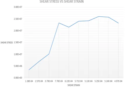
Graph shear stress vs strain.
The graph of shear stress and shear strain shows the material aluminum alloy A5052 characteristic is still maintained during the process. During the silting simulation process the parameter used from 10 Nm until 100Nm. At the first two parameters which is the 10Nm until 20Nm the material is still in elastic region and the modulus of rigidity can be calculated in the region. Until the 30Nm the material starts to enter plastic region until 100Nm which is the failure point.
Modulus of rigidity and elasticity
The modulus of rigidity or shear modulus is the elastic modulus that use for the deformation which takes place when a force is applied parallel to one face of the object while the opposite face is held fixed by another equal force. The bigger the shear modulus the more rigid is the material since for the same change in horizontal distance (strain). The shear modulus S is defined as the ratio of the stress to the strain.
Shear Modulus formula
[image:3.595.321.536.98.247.2]From the graph, the shear modulus can be calculated only in the elastic region between 10Nm until 20 Nm before the material start to enter plastic region. After that the value of the modulus of rigidity will be compared. The calculation has been calculated and the percentage value of error will be displayed.
Table shear modulus of Aluminum A5052
Torque
Modulus of Rigidity (simulation)
Modulus of Rigidity (Appendix 1)
% Error
10Nm 27.14E9 Pa 25.9E9 Pa 4.70%
Table Young’ Modulus
Young Modulus (Simulation)
Young Modulus
(Appendix 1) % Error
72.219E9 Pa 70.3E9 Pa 2.73
Force (Torque) to deformation
[image:4.595.59.284.147.343.2]Graph Torque Vs Deformation
Table shows the value of deformation for each of the load applied. After that the value of all deformation has been transferred in to graph. From the table and graph, there is a deformation on the specimen as load is applied from 10Nm until 100Nm. Pattern of the graph shows that as the larger load applied the displacement on the specimen of aluminum A5052 increases. Form the graph plotted above, the simulation results in SolidWorks shows the maximum deformation achieved for each load applied.
[image:4.595.316.537.380.677.2]Temperature result
Figure Temperature of 10 rad/sec.
Graph Temperature Vs Angular Velocity.
From the table and graph plotted above shows the effect of angular velocity to the temperature. The graph shows the increase of temperature constantly with the increase of angular velocity. The effect of the basic cutting temperature, such as turning particularly when it is high, is mostly tool rapid tool wear, which reduces tool life if the tool material is not the cutting edges due tobuilt-up-edge formation.
Cutting speed result
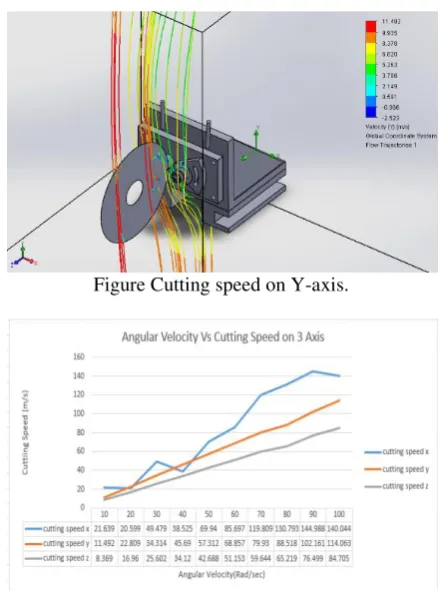
Figure Cutting speed on Y-axis.
Graph Angular Velocity Vs Cutting Speed
[image:4.595.61.281.491.632.2]shows the cutting speed rose up until 140.044 m/s. This means the maximum cutting speed for the analysis is at the X-axis and since the material aluminum A5052 is ductile the cutting speed can be in high-speed without changing the material characteristic.
CONCLUSIONS
This study has elucidated the effect prediction models of 3 parameters on High Speed Slitting Machine the parameter are cutting forces, Temperature and Cutting Speed. The first parameter is to study the effect of cutting forces on stress and strain. Temperature analysis has been done to predict the temperature rise during slitting process. It was observed that between rotational velocity affect the linear speed on all 3-axis. By the assumption of data, the analysis helps to calculate material characteristic value and it can be tested with variable material.
ACKNOWLEDGEMENTS
The authors would like to thank Faculty of Manufacturing Engineering, Faculty of Mechanical, Mechanical and Manufacturing Engineering Technology and Universiti Teknikal Malaysia Melaka (UTeM) for their support that enabled this work to be carried out through the grant of FRGS/2018/FTKMP-AMC/F00387
REFERENCES
[1] Rodríguez J., Carbonell J., Cante J. & Oliver J. 2017. Continuous chip formation in metal cutting processes using the Particle Finite Element Method (PFEM). International Journal of Solids and Structures, 120, 81-102. doi: 10.1016/j.ijsolstr.2017.04.030
[2] Markopoulos A. P. 2012. Cutting Mechanics and Analytical Modeling. Finite Element Method in Machining Processes Springer Briefs in Applied Sciences and Technology, 11-27. Doi: 10.1007/978-1-4471-4330-7_2
[3] Cao Y., Chen H. & Zhao H. X. 2013. Analysis of the Influence of Cutting Parameters on Cutting Force Based on Cutting Process Simulation. Advanced
Materials Research, 710, 223-227.