www.ijsrp.org
Numerical comparison on Shell side performance of
Helixchanger with center tube with different helix angles
Prof. Sunil S. Shinde*, Mr. Pravinkumar V. Hadgekar**
* Department of Mechanical Engineering Vishwakarma Institute of Technology, Pune (India) ** Department of Mechanical Engineering Vishwakarma Institute of Technology, Pune (India).
Abstract- Computational Fluid Dynamic (CFD) is a useful tool
in solving and analyzing problems that involve fluid flows, while
shell and tube heat exchanger is the most common type of heat
exchanger and widely use in oil refinery and other large chemical
processes because it suite for high pressure application. The
numerical simulation of Shell & Tube Heat Exchanger with
center tube called Helixchanger with center tube with different
baffle inclination is to be done. The processes in solving the
simulation consist of modeling and meshing the basic geometry
of Helixchanger using the CFD package ICEM CFD. Then, the
boundary condition will be set before been simulate in Fluent
based on the research papers experimental data. Finally results
has been examined in CFD-POST. Parameter that had been used
was the same parameter of experimental at constant mass flow
rate of hot water and varies with mass flow rate at 50,60,70 & 80
LPM of cold water. Thus, this report presents the simulation of
heat transfer & pressure drop in Helixchanger model with
different baffle inclination as 20, 25, 30 & 40 degree, which
gives insight of all parameters affect on Helixchanger design & it
also suggests the optimized helix angle which gives better heat
transfer with minimum pressure drop.
Index Terms- CFD, Helixchanger, Center tube, Heat transfer coefficient, Pressure drop.
I. INTRODUCTION
1.1 Background of study
Heat exchangers are devices in which heat is
transferred from one fluid to another. Heat exchangers are widely
used equipment in various industries such as process, power
generation, and transportation and refrigeration industry.
In addition to the basic need for transferring heat
there are certain additional requirements which tend to be
specific to the industry in which they are employed, Mukherji R.
et al., 1988. For example, the exchanger used in automotive and
aviation industry need to be lightweight. These exchangers as
well as those used in commercial and domestic refrigeration tend
to use the same types of fluid in many applications. The
exchangers used in chemical process industry tend to be used for
a wide variety of fluid types with different degree of cleanliness.
In contrast, the exchangers used in cryogenic applications
invariable handle relatively clean fluids. These and other similar
industry specific requirements have resulted in development of
different types of exchanger ranging from the conventional shell
and tube heat exchanger to other tubular and non tubular
exchangers of varying degree of compactness.
Shell and tube heat exchangers (STHXs) are widely
used in many industrial areas, such as power plant, chemical
engineering, petroleum refining, food processing, and etc. A
large percentage of world market for heat exchangers is served
by the industry workhorse, the shell-and-tube heat exchanger.
According to Master B.I. et al., 2006. more than 35-40 % of heat
exchangers are of the shell and tube type due to their robust
geometry construction, easy maintenance and possible upgrades.
Rugged safe construction, availability in a wide range of
materials, mechanical reliability in service, availability of
standards for specifications and designs, and long collective
operating experience and familiarity with the designs are some of
the reasons for its wide usage in industry. Recent developments
in other exchanger geometries have penetrated in various
industry applications; however, the shell and tube exchanger by
far remains the industry choice where reliability and
maintainability are vital. Over the years, significant research and
development efforts are devoted to better understand the
www.ijsrp.org process and equipment designers to improve industrial heat
transfer.
1.1.1 Shell and tube heat exchanger
The basic principle of operation is very simple as flows of two
fluids with different temperature brought into close contact but
prevented from mixing by a physical barrier. Then the
temperature between two fluids tends to equalize by transfer of
heat through the tube wall. The fluids can be either liquids or
gases on either the shell or the tube side. In order to transfer heat
efficiently, a large heat transfer area should be used, leading to
the use of many tubes. In this way, waste heat can be put to use.
This is an efficient way to conserve energy.
1.1.2 Helical Baffle Shell & Tube Heat Exchanger with
center tube (Helixchanger)
The concept of helical baffle heat exchangers was
developed for the first time in Czechoslovakia. The Helical baffle
heat exchanger, also known as Helixchanger, is a superior
shell-and-tube exchanger solution that removes many of the inherent
deficiencies of conventional segmental-baffle exchangers.
Helical baffle heat exchangers have shown very effective
performance especially for the cases in which the heat transfer
coefficient in shell side is controlled; or less pressure drop and
less fouling are expected Kral D et al., 1993. It can also be very
effective, where heat exchangers are predicted to be faced with
vibration condition. Quadrant shaped baffle segments are
arranged at an angle to the tube axis in a sequential pattern that
guide the shell side fluid to flow in a helical path over the tube
bundle. Helical flow path of the shell-side fluid can also be
achieved by a continuous helix shaped baffle running throughout
the length of the shell and tube heat exchanger.
Manufacturing of helical baffle is very difficult. In order
to avoid manufacturing difficulties of continuous helical baffles
in the center region, a center tube has to be installed, Chen G.D.
et al., 2011.
The helical flow provides the necessary
characteristics to reduce flow dispersion and generate near plug
flow conditions. It also ensures a certain amount of cross flow to
the tubes to provide high heat transfer coefficient. The shell-side
flow configuration offers a very high conversion of pressure drop
to heat transfer.
The Helixchanger design provides:-
Enhanced (Heat transfer performance/ Shell-side
pressure drop) ratio.
Reduced fouling characteristics.
Effective protection from flow-induced tube vibrations. It results in lower capital costs, reduced operating costs,
lower maintenance costs and consequently, significant
lower total life cycle costs.
For existing plants, the Helixchanger design helps to
increase the capacity while lowering maintenance cost,
plot space and energy costs.
It is better to consider the Helixchanger option when
investigating the following:-
[image:2.612.315.601.391.450.2] Plant upgrade with replacement tube bundles. Capacity expansion with limited plot space. Reduce fouling problems and frequent downtime
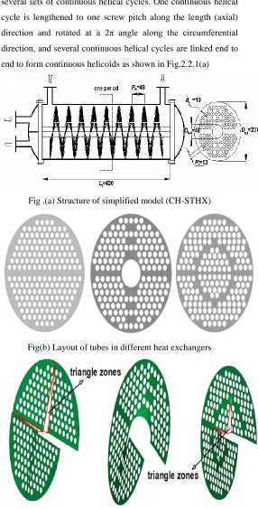
Fig. 1.1: Helical Baffled Shell & Tube Heat Exchanger
(Helixchanger)
According to Yong-gang Lei et al. the performance
of helixchanger depends on helix angle which determines
pressure drop on shell side i.e. pumping power required. The heat
transfer per unit pressure drop is a good metric for comparing the
performance. As we know heat exchangers are widely used
equipments in various mechanical, chemical, power generation
and refrigeration industry. The present well established process
design trend requiring high degree of heat recovery usually
results in installing a larger heat exchanger area. However adding
a few more heat exchangers causes an increase in pressure loss
together with a greater pumping power requirement.
On the shell side the conventional segmental baffles
exhibit rather high-pressure difference to produce sufficiently
www.ijsrp.org arrangement is needed. So, use of helical shaped baffles is
proposed.
The fluid flow pattern, particularly within the shell,
may significantly influence the heat exchanger efficiency. The
development of shell and tube exchanger centre on better
conversion of pressure drop into heat transfer by improving the
conventional baffle design.
2.Helixchanger & Segmental Heat Exchanger:
Conventional segmental baffles in shell and tube heat
exchangers, while having an excellent record of acceptance and
functionality, represent some limitations and shortcomings. In
particular, shell-side flow path is wasteful which causes
excessive pressure loss while recovering less heat transfer. This
particular arrangement of baffles also limits maximum thermal
effectiveness and encourages dead zones where fouling occurs,
Sirous Z. M. et al.,2012.
Time & money spends on heat exchanger cleaning
process for better performance. From fig. shown below it is
observed that the running time for helical baffle is 3 times more
than segmental baffle . It can be found out from mentioned
pictures that the fouling for helical baffles is significantly lower
and also distribution of fouling is more scattered all over the
surface of tubes. On the other hand, fouling for segmental baffles
is higher and is more accumulated on local areas. Accumulation
of fouling on local areas causes corrosion on the surfaces of
tubes and baffles and lowers the operation period of heat
[image:3.612.312.598.79.642.2]exchangers.
Fig.1.2 Running times of segmental and helical baffles.
2.1 Helixchanger with center tube:
Continuous helical baffles are manufactured by linking
several sets of continuous helical cycles. One continuous helical
cycle is lengthened to one screw pitch along the length (axial)
direction and rotated at a 2π angle along the circumferential
direction, and several continuous helical cycles are linked end to
end to form continuous helicoids as shown in Fig.2.2.1(a)
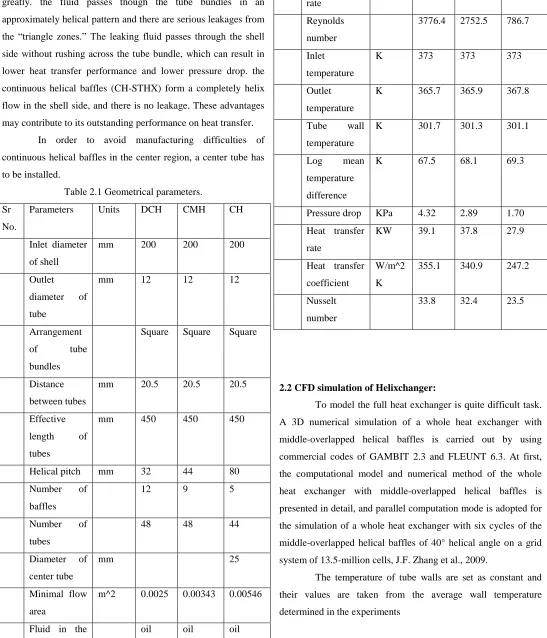
Fig .(a) Structure of simplified model (CH-STHX)
Fig(b) Layout of tubes in different heat exchangers
Fig(c) Structure of helical baffles in different heat exchangers
Fig. 1.3 Computational models of shell-and-tube heat exchangers
with three different helical baffles (DCH STHX, CH-STHX and
[image:3.612.40.273.546.696.2]www.ijsrp.org Compared with the DCH-STHX, the “triangle zones” in
CMH-STHX, which resulted in leakage, have been decreased
greatly. the fluid passes though the tube bundles in an
approximately helical pattern and there are serious leakages from
the “triangle zones.” The leaking fluid passes through the shell
side without rushing across the tube bundle, which can result in
lower heat transfer performance and lower pressure drop. the
continuous helical baffles (CH-STHX) form a completely helix
flow in the shell side, and there is no leakage. These advantages
may contribute to its outstanding performance on heat transfer.
In order to avoid manufacturing difficulties of
continuous helical baffles in the center region, a center tube has
[image:4.612.34.581.96.734.2]to be installed.
Table 2.1 Geometrical parameters.
Sr
No.
Parameters Units DCH CMH CH
Inlet diameter
of shell
mm 200 200 200
Outlet
diameter of
tube
mm 12 12 12
Arrangement
of tube
bundles
Square Square Square
Distance
between tubes
mm 20.5 20.5 20.5
Effective
length of
tubes
mm 450 450 450
Helical pitch mm 32 44 80
Number of
baffles
12 9 5
Number of
tubes
48 48 44
Diameter of
center tube
mm 25
Minimal flow
area
m^2 0.0025 0.00343 0.00546
Fluid in the oil oil oil
shell side
Mass flow
rate
M^3/hr 10.11 10.11 10.11
Reynolds
number
3776.4 2752.5 786.7
Inlet
temperature
K 373 373 373
Outlet
temperature
K 365.7 365.9 367.8
Tube wall
temperature
K 301.7 301.3 301.1
Log mean
temperature
difference
K 67.5 68.1 69.3
Pressure drop KPa 4.32 2.89 1.70
Heat transfer
rate
KW 39.1 37.8 27.9
Heat transfer
coefficient
W/m^2
K
355.1 340.9 247.2
Nusselt
number
33.8 32.4 23.5
2.2 CFD simulation of Helixchanger:
To model the full heat exchanger is quite difficult task.
A 3D numerical simulation of a whole heat exchanger with
middle-overlapped helical baffles is carried out by using
commercial codes of GAMBIT 2.3 and FLEUNT 6.3. At first,
the computational model and numerical method of the whole
heat exchanger with middle-overlapped helical baffles is
presented in detail, and parallel computation mode is adopted for
the simulation of a whole heat exchanger with six cycles of the
middle-overlapped helical baffles of 40° helical angle on a grid
system of 13.5-million cells, J.F. Zhang et al., 2009.
The temperature of tube walls are set as constant and
their values are taken from the average wall temperature
www.ijsrp.org After validation its found that the cycle average Nusselt
number of different cycle in the heat exchanger & pressure drop
within the accuracy allowed in engineering computation hence
periodic model for one cycle can be used to investigate the heat
transfer and pressure drop characteristics for different heat
[image:5.612.314.576.99.450.2]exchanger to save computational source, J.F. Zhang et al., 2009.
Fig. 1.4 Specifications of specified surfaces and geometric cycle
units.
For the case studied the difference between the 2nd cycle and the
fifth cycles are both less than 2% for both pressure drop and heat
transfer. Thus for the performance simulation of a STHXHB
periodic model for one cycle can be used to investigate its
performance without inducing large error.
Some researches indicated that the larger the helix
angle, the better shell-side comprehensive performance of
STHXCH when helix angle is less than 45◦. However, a large
helix angle, or in other words a large helix pitch, has some
adverse effects: first, the shell-side velocity becomes small under
the same mass flow rate, which goes against heat transfer;
second, the quantity of helical cycle is small, which means the
helix flow is possibly not fully developed until it reaches the
shell-side outlet; third, the unsupported span on the tube bundles
is large, which is not favorable for the prevention of
fluid-induced vibration in the shell side, Ji shui et al., 2011.
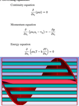
3 Governing equations:
Continuity equation
( )
Momentum equation
( )
Energy equation
( )
[image:5.612.37.293.163.317.2]Fig. 1.5 Insight of a one cycle Helixchanger with center tube
Table: Baffle pitch
k-ԑ realizable turbulence model is applied. The governing
equations are iteratively solved by using SIMPLE
pressure-velocity coupled algorithm. The convergence criteria for energy
variable (T) is < 10^-6. The sum of the normalized absolute
residuals in each control volume for other flow variables (such as
ui, p) are controlled to be < 10^-3. Each solution takes
approximately 4-5 CPU hours to converge on personal computer
having 8GB RAM & 2.1 GHZ processor.
Numerical validation: Sr
No
Helix angle in
degree (α)
Baffle pitch
(mm)= π Di tanα
No. of
baffles
1 20 175 6
2 25 224 5
3 30 277.5 4
[image:5.612.33.299.405.520.2]www.ijsrp.org Computational results were compared with the Periodic model
with continuous helix, Zhang J.F. et al., 2009 and it is found that
the good agreement in trend of shell side heat transfer
coefficient versus mass flow rate.
[image:6.612.317.585.57.214.2]Computational Results
Figure 1.6 Vector plot for Helixchanger with center tube.
[image:6.612.38.303.142.229.2]The velocity vector distributions & streamlines on the axial sections of shell side fluid are shown in Figure. The shell-side fluids pass through the tube bundles basically in a helical pattern and rush the heat exchange tubes with an inclination angle. On the one hand, helical flow avoids abrupt turns of flow. On the other hand, it changes the cross section shape of tube in flow direction into ellipse. Therefore, it can reduce the pressure drop in shell side and the vibration of tube bundle.
Table: Geometrical parameters
Figure 1.7 Velocity streamlines for Helixchanger with center
[image:6.612.315.580.268.415.2]tube.
Figure 1.8 Heat transfer coefficient vs Helix angle
Figure 1.9 Pressure drop for one cycle
Conclusion 1000 1200 1400 1600 1800
15 20 25 30 35 40 45
Sh
ell
side
hea
t
tra
ns
fer
co
ef
ficient
(
W/m
^2
)
Helix angle in degree
Heat transfer coefficient vs Helix angle
HTC
5 10 15 20 25 30
15 20 25 30 35 40 45
P
re
ss
ure
dro
p (
P
a
)
Helix angle in degree
Pressure drop drop for one cycle
Pressure drop
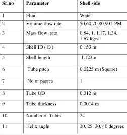
Sr.no Parameter Shell side
1 Fluid Water
2 Volume flow rate 50,60,70,80,90 LPM
3 Mass flow rate 0.84, 1, 1.17, 1.34, 1.67 kg/s
4 Shell ID ( Di) 0.153 m
5 Shell length
1.123m
6 Tube pitch
0.0225 m (Square)
7 No of passes
1
8 Tube OD 0.012 m
9 Tube thickness 0.0014 m
10 Number of Tubes 24
[image:6.612.329.581.451.718.2] [image:6.612.37.303.457.611.2]www.ijsrp.org In this paper, numerical simulations of
Helixchanger with center tube with different baffle
inclination angles are performed to reveal the effects of
baffle inclination angle on the heat transfer and pressure
drop characteristics. And based on those characteristics
to provide an optimal baffle inclination angle for the
required range of heat transfer coefficient and available
pumping power. The major findings are summarized as
follows:
As helix angle decreases, the baffle pitch decreases and
for the same mass flow shell side velocity increases and
hence it leads to increase in heat transfer coefficient.
Shell side pressure drop decreases with increase in helix
angle because baffle pitch increases & flow achieves
smooth behavior in shell side.
Ratio HTC/Pressure drop is higher for helix angle >35º
but along with this we should take into account
achievable HTC (heat transfer coefficient) range by
given helix angle as after certain Pressure drop, HTC
values becomes flat. Therefore observing only the ratio
of HTC/Pressure drop will not be sufficient, along with
that we should take into account plot of HTC versus
pressure drop per unit length also. So even
HTC/Pressure drop is high for 400 helix angle, its HTC
is very small compared to other helix angles.
REFERENCES
[1] R.Mukherjee, "Effectively design Shell and Tube Heat exchangers", Chemical Engg Progress, 1998, pp. 1-8.
[2] B.I.Master,K.S.Chunagad,A.J.Boxma,D.Kral,P. Stehlik, “Most Frequently used Heat exchangers from pioneering Research to Worldwide Applications”, vol. No.6, 2006, pp. 1-8.
[3] D. Kral and J. Nemcansky, “The Helixchanger-Helically Baffled heat exchanger”, ICHMT Int Symposium on New Developments in Heat Exchanger, Portugal, 1993,pp. 467-477.
[4] Sirous Zeyninejad Movassag Bin Li, Wen-Jiang Huang, Yong-Gang Lei, Ya-Ling He,Wen-Quan Tao. "Tube bundle replacement for segmental and helical shell and tube heat exchangers: Performance comparison and fouling investigation on the shell side", 2012, pp, 1162-1169.
[5] Gui-Dong Chen, Min Zeng, & Qiu-WangWang, "Experimental and Numerical studies on Shell side performance of three different Shell & Tube Heat Exchangers with Helical Baffles", 2011, pp, 449-463.
[6] Yong-Gang Lei,Ya-Ling He,Rui Li,Ya-Fu Gao, “Effects of baffle inclination angle on flow and heat transfer of a heat exchanger with helical baffles”, ScienceDirect-Chemical Engineering and Processing,2008, pp.1-10,
[7] Jian-Fei Zhang, Ya-Ling He, Wen-Quan Tao "3D Numerical simulation on STHX with middle overlapped helical baffles & continuous baffle", 2009, pp. 1-10.
[8] Prithiviraj, M., and Andrews, M. J.,. "Three Dimensional Numerical Simulation of Shell-and-Tube Heat Exchangers", Part 1: Foundation and Fluid Mechanics, Numerical Heat Transfer Part A: Applications, vol. 33, no. 8, 1998, pp, 799–816.
[9] H.K. Versteeg and W. Malalasekera An Introduction to Computational Fluid Dynamics The Finite Volume method, (Longman Scientific and Technical), 1-83.
AUTHORS
Prof. Sunil S. Shinde Assistant Professor at Vishwakarma Institute of Technology, Pune, India. Received M.E. in Mechanical Engineering with Heat Power as specialization from College of Engineering, Pune. Presently, pursuing Ph.D. in Mechanical Engineering from University of Pune. Research includes Design, Simulation and Experimentation in tubular heat exchangers.15 years of teaching & research experience in various subjects of Mechanical Engineering, guided about 15 M.E. theses & number of B.E. projects. Around 6 publications in various national & international journals & conference proceedings. e mail:[email protected]
Pravinkumar V. Hadgekar M.Tech Heat Power from Vishwakarma Institute of Technology, Pune, having 2 year of industrial & 2 years of teaching experience.