Reliable Train Network with Active Supervisor
Mai Ibrahim, Ramez M. Daoud, Hassanein H. Amer Electronics Engineering Department, American University in Cairo, Cairo, Egypt
Email: [email protected], [email protected], [email protected]
Received March 19, 2013; revised April 20, 2013; accepted April 30,2013
Copyright © 2013 Mai Ibrahim et al. This is an open access article distributed under the Creative Commons Attribution License, which permits unrestricted use, distribution, and reproduction in any medium, provided the original work is properly cited.
ABSTRACT
In this paper, a new reliable hierarchical model is suggested for a two-wagon train Networked Control System. Each wagon has a Controller that carries the control load and an Entertainment server that handles the entertainment. A su-pervisory controller runs on top of the two controllers and the two entertainment servers. Contrary to a similar model in the literature, the Supervisory node replaces a Controller as soon as it fails (Active Supervisor). All system states are analyzed and simulated using OPNET. It is shown that, for all states, this architecture has zero control packets dropped and the end-to-end delay is below the maximum target delay. A comparison between this Active model and the other model in the literature is presented. It is found that the entertainment in this new architecture is kept available for the passengers in more of the system states when compared to the architecture previously presented in the literature.
Keywords: Ethernet; Train; Networked Control Systems; Active Supervisor; Hierarchical Architecture
1. Introduction
In industrial and transportation systems, Networked Con- trol Systems (NCSs) are currently widely applied [1-4]. Previously, deterministic protocols that ensure meeting critical real-time delays and no packet loss for the small control packets such as Controller Area Network (CAN), PROFIBUS and PROFINET, were used [5,6]. Ethernet (IEEE Std. 802.3) [7], despite its non-deterministic na- ture, is a promising protocol that is being applied in NCS [8,9]. Packet Scheduling and reformatting the Ethernet packet were the main approaches to overcome the non- deterministic nature of Ethernet [10,11]. Furthermore, Rockwell automation, the ODVA, EtherNet/IP, TT Eth- ernet and FTT Ethernet have implemented different mo- difications to the protocol, some of which are in the course of standardization [12-16].
Train operation, safety, collision avoidance and ex-change of information are the main tasks to be handled by the train networks [17]. As the demand for more and more entertainment services on board of trains is in-creasing, Ethernet became a promising technology.
Due to its large bandwidth, Gigabit Switched Ethernet was successfully tested as a one-wagon train network to carry both control and entertainment loads within a wa-gon [18]. The entertainment load is represented as video streams and running Wi-Fi applications [18]. The net-work model was further enhanced to increase its reliabil-ity at the Server level [19]. In [19], the authors used
one server to handle each type of load. The control load was handled by the Control Server (Controller) and the entertainment was handled by the entertainment server. The entertainment server acted as a backup for the Con-troller; it would handle the control load in case of the Controller failure [19]. Simulations proved that the re-quirements on the control packet end-to-end delays were met in both [18,19]. The reliability of the network was further enhanced and its performability was calculated [20,21].
In this research, a two-wagon train control network using unmodified Ethernet is presented. A hierarchal structure at the Server level, including an active supervi-sor, is simulated. As soon as a controller fails, this active supervisor replaces it and carries its load. The system is modeled using OPNET network simulation tool [22]. The control packets are sampled at different sampling periods [23]. Furthermore the entertainment load is si-mulated as compressed DVD video streaming and 4 dif-ferent Wi-Fi applications which are web-browsing, FTP, database and email access. Additionally, the network is simulated in all possible faulty server states as well as the fault-free state. It will be shown that the architecture with an active supervisor will function correctly irrespective of server failures. The architecture will then be compared to the one presented in [24].
hie-rarchal Ethernet train networks. In Section 3, the newly proposed model will be illustrated. Simulated scenarios and their outcomes shall be discussed in Section 4. Sec-tion 5 concludes this paper.
2. Background
In [24,25], the authors proposed a Gigabit Ethernet train network using the unmodified IEEE 802.3 standard; a hybrid model was introduced in which multiple control sampling periods were used. More details about this hy-brid model are presented below.
2.1. Hybrid Network Model
In the IEC 61375 Standard (Trains network Standard), different sensor/actuator sampling periods are specified [23]. In [18,19], only one sampling period is simulated per network scenario; one scenario uses the 1 ms pling rate while the other scenario uses the 16 ms sam-pling rate. According to [23], 16 ms is the samsam-pling pe-riod of the majority of train sensors/actuator and 1ms is the smallest sampling period in a train network. In [24], the authors formulated the network to contain different sampling periods, specifically combination of 16 ms and 1 ms.
A train wagon contains a total of 250 sensor/actuator nodes. In [18,19], only 1:1 sensor:actuator ratio is simu-lated, but in [24,25], the network contained more diverse combinations of sensors:actuators to simulate a more realistic scenario. The sensor/actuators were divided into 3 different groups with different sensor:actuator ratios.
2.2. Passive Supervisor
In [24], the authors presented a hierarchal control struc-ture including having a Passive Supervisor node in addi-tion to the 2 servers per wagon, resulting in a total of 4 servers and a supervisor. This node is assumed to be the most reliable node in the network; it acts as a backup for any controller after all other Servers/Controllers have failed.
In case the Controller fails in one of the wagons, the Entertainment Server drops its main functionality (han-dling the entertainment load) in order to handle the wagon’s control load. For the Entertainment Server to handle the control load, the sensors send 4 streams of their data to the Controllers and the Entertainment Serv-ers. Only the Server handling the control load is the one responsible for making the control decision and sending the control action to the corresponding actuator. If both
Servers in a wagon (Wi) fail (the Controller Ki and the
Entertainment Server Ei), the Entertainment Server (Ej)
of the other wagon (Wj) drops its entertainment load and
handles the Wi control load [24].
If three of the four Servers fail, then the remaining
op-erational server in a wagon (Wj) (either Controller Kj or
Entertainment Server Ej) handles its own wagon load.
This is also the point at which the Supervisor starts to come into action and handles the control load of the other
entirely-failed wagon Wi. The sensors of both wagons
start to send their data to the Supervisor node after the failure of three Servers. In case of the failure of all four servers, the Supervisor node will handle the control load of both wagons; this is again under the assumption that the Supervisor will be the last to fail among all Servers/ Controllers.
3. Proposed Network Model
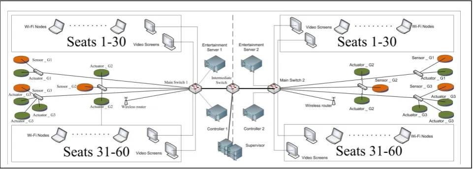
The same network architecture presented in [24] is used in this study for comparison purposes. The network con-sists of 2 single wagon networks interconnected via a switch (Intermediate Switch) and a 10 Gb link to a Su-pervisor Node. This 2-wagon model represents the main train building unit such as the Siemens Desiro diesel or the Siemens electric multiple unit (DMU or EMU) [26]. The two-wagon train unit network model is illustrated in
Figure 1.
There are 60 seats per wagon [27]. In each wagon, all nodes are connected to the wagon’s Main Switch (MS) via Gigabit Ethernet fabric. The forwarding rates of the two Main Switches and the Intermediate Switch are 6.6 Mpps [24]. This rate is much lower than 38.2 Mpps, the forwarding rate of the commonly available switches in the market such as the Cisco Catalyst 3560 Gigabit Ethernet switch [28].
Each wagon has 250 nodes (Sensors/ actuators) di-vided into 3 groups with different sensor:actuator ratio as in [24,25]. Group 1 (G1) has a 1:1 sensor:actuator ratio, Group 2 (G2) has a 2:1 sensor:actuator ratio and Group 3 (G3) has a 3:1 sensor:actuator ratio. There are 60 nodes in G1 running at a sampling period of 1ms, 150 nodes in G2 and 40 nodes in G3. Nodes in G2 and G3 are running
at a sampling period of 16 ms [24,25]. To simulatethe
worst end-to-end delay for the control packets, the sen-sors/actuators are located to ensure maximum propaga-tion time.
Moreover, the same entertainment services are run in the form of 60 Wi-Fi nodes (one laptop per seat), running 4 different applications as in [24]: web-browsing, FTP, database and e-mail access. These nodes/laptops are connected to the wagon MS via a wireless router. Also, 60 Compressed DVD video streams are running at a rate of 5 Mbps connected to the MS of each wagon [29].
Figure 1. Two-wagon train model.
the Supervisor node. This watchdog enables all Servers and the Supervisor to be aware of the status of the other Servers. Also, there are 4 cameras per wagon located at each door to enhance safety [30]. They send video sig-nals directly to the Supervisor for safety monitoring pur-poses by the train driver. The reliability of the Supervisor is assumed to be the highest as in [24] to ensure it has the lowest probability of failure and therefore the longest lifetime for comparison purposes.
Active Supervisor
In this research, unlike the previous system, the
Supervi-sor acts as an Active Supervisor. It is the primary
back-up for the Controllers (Ks) in each wagon. If the Con-troller in either wagon fails, the Supervisor handles the control load of the wagon. Additionally, in case the Con-troller of the second wagon fails, the Supervisor in such case will handle the control load of both wagons.
The fault-tolerance relation between the Controllers in
both wagons is no longer present, i.e., they no longer
carry each other’s control load. Furthermore, the Enter-tainment Servers do not act as backups to the Controllers and do not handle any control load unlike the presented case in [24]. In regard to entertainment services, the same conservative approach followed in [24] is still applied. If the Entertainment Server fails, the entertainment services are dropped due to the high safety requirements in train operations. However, the Entertainment Server does not drop the entertainment load to handle any control load.
The sensors send their data only to their corresponding Controller and to the Supervisor. So, for example, the sensors in wagon 1 only send their data to Controller 1 (K1) and the Supervisor as these are the only nodes to handle the control load.
4. Simulation Outcomes
In [24], the simulations presented the outcomes for the
unique states which the network experiences. The same approach is used in this research. However, after analyz-ing the unique states of functionanalyz-ing Servers at a time, only 10 scenarios need to be simulated using OPNET network simulator. Please note that the simulation of only the unique states means that all possible scenarios are accounted for by the simulations, because they are represented by one of those unique states.
4.1. Simulated Scenarios
In [24], 11 unique states were simulated. In this research
however, only 10 states are needed. Table 1 shows the
10 unique states that have been simulated using OPNET. The scenarios simulate all the possible combinations of operational Servers that the network can go through. The main measuring metric for network performance is the
control packet end-to-end delay. As shown in Table 1,
all end-to-end delays are below the sampling periods of the corresponding group, thus, fulfilling the delay re-quirement [31]. Also, in the column labeled Entertain-ment, the entertainment services are on in the specified wagons.
In [24], there were 11 scenarios simulated while here, only 10 states are simulated. This is due to the fact that,
in [24], Scenario EiS appeared twice. In the first case the
Entertainment Server (Ei) was carrying the control load
of Wagon Wi, while in the second case, it was carrying
the control load of the other Wagon Wj. As the
Enter-tainment Server in this research does not handle any con-trol load, consequently, both cases end up being identical. In the active case, the supervisor node carries the control load of both wagons while each entertainment server handles its own wagon entertainment load.
0.411 µs. Furthermore, the delays for the door cameras and the video streaming were below the acceptable delay requirements. As per [32], the OPNET results presented in this research are comparable to hardware implementa-tion outcomes.
For completeness, Table 2 has the corresponding data
for the Passive Supervisor architecture presented in [24].
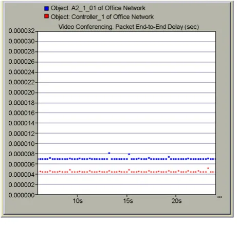
Figures 2-4 illustrate a sample of the OPNET results for the Active Supervisor architecture.
[image:4.595.309.539.86.296.2]In all figures, the x-axis is the simulation time in seconds and the y-axis is the delay in seconds. The red dots in the graphs are the delay from the sensor to the controller and the delay from the controller to the actua-tor are the blue dots.
Table 1. Total end-to-end delay (µs)—active supervisor.
Scenarios Simulated
Server Handling
Control Load G1 G2 G3 Entertainment Wi Wj
KiKjEiEjS Ki Kj 26.55 14.24 21.14 Wi, Wj
KiEiEjS Ki S 17.12 12.22 19.12 Wi, Wj
KiKjEiS Ki Kj 17.98 13.22 15.99 Wi
KiEiS Ki S 14.41 11.63 16.45 Wi
KiEjS Ki S 9.77 11.50 9.50 Wj
KiKjS Ki Kj 15.07 12.18 15.71 -
EiEjS S S 17.02 12.17 17.98 Wi, Wj
KiS Ki S 11.85 11.76 12.54 -
EiS S S 9.36 11.33 9.10 Wi
S S S 12.4 11.3 9.2 -
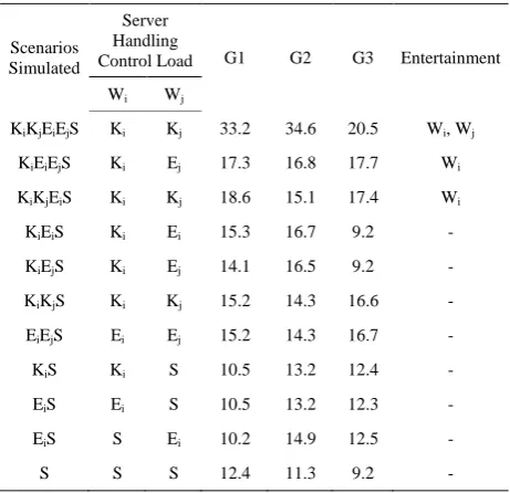
Table 2. Total end-to-end delay (µs)—passive supervisor [24].
Scenarios Simulated
Server Handling
Control Load G1 G2 G3 Entertainment Wi Wj
KiKjEiEjS Ki Kj 33.2 34.6 20.5 Wi, Wj
KiEiEjS Ki Ej 17.3 16.8 17.7 Wi
KiKjEiS Ki Kj 18.6 15.1 17.4 Wi
KiEiS Ki Ei 15.3 16.7 9.2 -
KiEjS Ki Ej 14.1 16.5 9.2 -
KiKjS Ki Kj 15.2 14.3 16.6 -
EiEjS Ei Ej 15.2 14.3 16.7 -
KiS Ki S 10.5 13.2 12.4 -
EiS Ei S 10.5 13.2 12.3 -
EiS S Ei 10.2 14.9 12.5 -
[image:4.595.307.538.329.542.2]S S S 12.4 11.3 9.2 -
Figure 2. Fault-free scenario (KiKjEiEjS)—G2.
Figure 3. One controller and one entertainment server in different wagons (KiEjS)—G3.
4.2. Outcomes Comparison
When comparing the outcomes with the results in [24], it
can be noticed that, in the fault-free scenario (KiKjEiEjS),
the delay is generally lower in the Active supervisor ar-chitecture. This is due to the fact that the sensors send their data to their corresponding controller and the super-visor node only rather than 4 different streams to all Servers (2 Controllers and 2 Entertainment Servers).
In other scenarios such as KiEiEjS, in [24], the
Con-troller node (Ki) carries the control load of wagon Wi
while the Entertainment Server (Ej) has dropped its
[image:4.595.57.288.513.736.2]Figure 4. Supervisor only (S)—G1.
In this research, since Ej does not drop its entertainment
load, S handles the control load of wagon Wj. Hence, the
passenger can still enjoy the on-board services and will not be affected by the failure that occurred.
Also, in case of EiEjS in the active model, the
super-visor S handles the control load of both wagons but the entertainment services are still running in both wagons. In [24], each of the Entertainment Servers carries its own wagon control load after dropping the entertainment load. Therefore, the delay in the Active Supervisor case is somewhat higher when compared to the Passive super-visor case.
Comparing another scenario such as “S”, the delay is the same in the active or passive models since all the entertainment is dropped in both cases and the sensors only send their data to the supervisor. When monitoring the forwarded traffic by the intermediate switch it was verified that the same amount of traffic (133.9 Mbps) was forwarded.
The main benefit when comparing the active supervi-sor case to the passive supervisupervi-sor case presented in [24] is that the passenger will only be affected by a failure when the entertainment server of the wagon fails.
Con-sider scenarios KiKjEiEjS, KiEiEjS and EiEjS; in these
three scenarios, the entertainment is functional in both wagons. On the other hand, in the passive scenario, the entertainment is functional in both wagons in the fault free scenario only. Also, only one wagon will experience
the failure of the entertainment in scenarios KiKjEiS,
KiEiS, KiEjS, and EiS. When comparing with the passive
scenario, the passengers will enjoy the entertainment
ser-vices in one wagon only in scenarios KiEiEiS and KiKjEiS.
[image:5.595.308.537.103.154.2]Table 3 shows a comparison between the Active Su- pervisor architecture and the passive Supervisor archi-
Table 3. Number of states with enabled entertainment.
Entertainment
Enabled in Passive Supervisor Active Supervisor 2 Wagons 1/18 States 4/16 States
1 Wagon 4/18 States 8/16 States
tecture with respect to the number of states that have the entertainment enabled in either one or two wagons. Due to the symmetric nature of the network, the states:
KiEiEjS, KiKjEiS, KiEiS, KiEjS, KiS and EiS are
dupli-cated. Consequently, in the Active Supervisor architec-ture, the 10 states are expanded to 16 and, in the Passive Supervisor architecture, the 11 states are expanded to 18.
Note finally that, in the Active Supervisor architecture, when the controller of a wagon fails, its only backup is the Supervisor node. In [24], for each failing controller, there are 4 other machines that act as backups.
5. Conclusions
Ethernet is an interesting technology in the field of Net-worked Control Systems. The use of Gigabit Switched Ethernet on-board of trains has already been reported in the literature. Previously, a hybrid network model was proposed for a two-wagon network model. Furthermore, a hierarchal structure at the controller level was proposed. However, the supervisor node was a passive one and it only handled the control load as a last resort.
In this paper, a new role was defined for the supervisor. As soon as either Controller fails, it acts as a backup for that failed Controller and handles its control load; there-fore, it became an active node. For safety purposes, no other node acted as backup for any failing Entertainment Server; the entertainment was dropped when the Enter-tainment server failed.
All possible combinations of operational Servers/ Controllers were simulated using OPNET. It was shown that the control packet end-to end delays met the control requirements and that no packet was dropped. The net-work was proven to function properly even after the fail-ure of all Controllers and Entertainment Servers; the Su-pervisor was able to successfully carry the control load of both wagons. It was also shown that this architecture has the advantage of keeping entertainment services opera-tional for a longer period when compared to other hie-rarchical architectures in the literature.
REFERENCES
[1] N. Navet, Y. Song, F. Simonot-Lion and C. Wilwert, “Trends in Automotive Communication Systems,” Pro- ceedings of the IEEE, Vol. 93, No. 6, 2005, pp. 1204-1223. doi:10.1109/JPROC.2005.849725
Proceedings of the IEEE International Conference on Industrial Technology ICIT, Hammamet, 8-10 December 2004, pp. 869-873.
[3] J. D. Decotignie, “Ethernet-Based Real-Time and Indus- trial Communications,” Proceedings of the IEEE, Vol. 93, No. 6, 2005, pp. 1102-1117.
doi:10.1109/JPROC.2005.849721
[4] R. M. Daoud, H. H. Amer, H. M. Elsayed and Y. Sallez, “Fault-Tolerant On-Board Ethernet-Based Vehicle Net- works,” Proceedings of the 32nd Annual Conference of the IEEE Industrial Electronics Society IECON, Paris, 6-10 November 2006, pp. 4662-4665.
[5] “CAN in Passenger and Cargo Trains,” CAN in Automa- tion, 2011. http://www.can-cia.org/
[6] Official Site for PROFIBUS and PROFINET. http://www.profibus.com/
[7] IEEE 802.3 Standard.
[8] T. Skeie, S. Johannessen and C. Brunner, “Ethernet in Substation Automation,” IEEE Control Systems, Vol. 22, No. 3, 2002, pp. 43-51. doi:10.1109/MCS.2002.1003998 [9] F. L. Lian, J. R. Moyne and D. M. Tilbury, “Performance
Evaluation of Control Networks: Ethernet, ControlNet, and DeviceNet,” IEEE Control Systems Magazine, Vol. 21, No. 1, 2001, pp. 66-83. doi:10.1109/37.898793 [10] S. H. Lee and K. H. Cho, “Congestion Control of High-
Speed Gigabit-Ethernet Networks for Industrial Applica- tions,” Proceedings of the IEEE International Symposium on Industrial Electronics ISIE,Pusan, 12-16 June 2001, pp. 260-265.
[11] J. S. Meditch and C. T. A. Lea, “Stability and Optimiza- tion of the CSMA and CSMA/CD Channels,” IEEE Tran- sactions on Communications, Vol. 31, No. 6, 1983, pp. 763-774. doi:10.1109/TCOM.1983.1095881
[12] ODVA, “EtherNet/IP Adaptation on CIP,” CIP Common, 2007. http://www.odva.org/
[13] Allen-Bradley, “EtherNet/IP Performance and Applica- tion Guide,” Rockwell Automation Application Solution, 2003.
http://ab.rockwellautomation.com/networks-and-commun ications/ethernet-ip-network
[14] J. Ferreira, P. Pedreiras, L. Almeida and J. Fonseca, “Achieving Fault-Tolerance in FTT-CAN,” Proceedings of the 4th IEEE International Workshop on Factory Com- munication Systems WFCS, Vasteras, August 2002, pp. 125-132. doi:10.1109/WFCS.2002.1159709
[15] P. Pedreiras, L. Almeida and P. Gai, “The FTT- Ether-netProtocol: Merging Flexibility, Timeliness and Effi-ciency,” Proceedings of the IEEE Euromicro Con- fe-rence on Real-Time Systems ECRTS, Vienna, 19-21 June 2002, pp. 134-142.
[16] K. Steinhammer and A. Ademaj, “Hardware Implementa- tion of the Time-Triggered Ethernet Controller,” Embed- ded System Design: Topics, Techniques and Trends, Vol.
231, Springer, Boston, 2007, pp. 325-338. doi:10.1007/978-0-387-72258-0_28
[17] G. Krambles, J. J. Fox and W. J. Bierwagen, “Automatic Train Control in Rapid Transit,” 1976.
http://www.interstatetraveler.us
[18] M. Aziz, B. Raouf, N. Riad, R. M. Daoud and H. M. El-
Sayed, “The Use of Ethernet for Single On-Board Train Network,” Proceedingsof the IEEE International Con- ference on Networking, Sensing and Control ICNSC, Hainan, 6-8 April 2008, pp. 1430-1434.
[19] M. Hassan, S. Gamal, S. Louis, G. F. Zaki and H. H. Amer, “Fault Tolerant Ethernet Network Model for Con- trol and Entertainment in Railway Transportation Sys- tems,” Proceedings of the Canadian Conference on Elec- trical and Computer Engineering CCECE, Niagara Falls, 4-7 May 2008, pp. 771-774.
[20] T. K. Refaat, H. H. Amer and R. M. Daoud, “Reliable Architecture for a Two-Wagon Switched Ethernet Train Control Network,” Proceedings of the 3rd IEEE Interna- tional Congress on Ultra Modern Telecommunications and Control Systems ICUMT, Budapest, 5-7 October 2011, pp. 1-7.
[21] T. K. Refaat, H. H. Amer, R. M. Daoud and M. S. Moustafa, “On the Performability of On-Board Train Networks with Fault-Tolerant Controllers,” Proceedings of the IEEE International Conference on Mechatronics ICM, Istanbul, 13-15 April 2011, pp. 743-748.
[22] Official Site for OPNET. www.opnet.com
[23] “Train Communication Network, IEC 61375,” Interna- tional Electrotechnical Committee, Geneva, 1999. http://www.iec.ch
[24] M. Hassan, R. M. Daoud and H. H. Amer, “Passive Su- pervisor for Railway Fault-Tolerant Ethernet Networked Control Systems,” Proceedings of the IEEE International Conference on Emerging Technologies and Factory Auto- mation ETFA, Toulouse, 5-9 September 2011, pp. 1-4. [25] T. K. Refaat, M. Hassan, R. M. Daoud and H. H. Amer,
“Ethernet Implementation of Fault Tolerant Train Net- work for Entertainment and Mixed Control Traffic,”
Journal of Transportation Technologies, Vol. 3, No. 1, 2013, pp. 105-111. doi:10.4236/jtts.2013.31010
[26] H. Glickenstein, “New Developments in Land Transpor- tation,” IEEE Vehicular Technology Magazine, Vol. 5, No. 2, 2010, pp. 17-20. doi:10.1109/MVT.2010.936653 [27] “Trains Reference List,” Siemens AG Transportation
Systems Trains, pp. 41-46.
http://w3.siemens.com/topics/global/en/sustainable-cities/ Pages/home.aspx
[28] Official Site for Cisco Catalyst 3560 Series Switch. http://www.cisco.com
[29] Video Charg, “Description of the Supported Formats,” 2010. http://www.videocharge.com/articles.php?id=1 [30] J. D. Swanson and C. Thornes, “Light Rail Transit Sys-
tems,” IEEE Vehicular Technology Magazine, Vol. 5, No. 2, 2010, pp. 22-27. doi:10.1109/MVT.2010.936645 [31] R. M. Daoud, “Wireless and Wired Ethernet for Intelligent
Transportation Systems,” D.Sc. Dissertation, Universite de Valenciennes et du Hainaut-Cambresis, Valenciennes, 2008.