Cross-layer Resource Allocation on Broadband Power
Line Based on Novel QoS-priority Scheduling Function
in MAC Layer
Huang Qian, Lu Jun, Xiong Chen, Duan Ruichao
School of Electrical and Electronic Engineering, North China Electric Power University, Beijing, China Email: [email protected], [email protected], [email protected], [email protected]
Received May, 2013
ABSTRACT
Traditional resource allocation algorithms use the hierarchical system, which does not apply to the bad channel envi-ronment in broadband power line communication system. Introducing the idea of cross-layer can improve the utilization of resources and ensure the QoS of services. This paper proposes a cross-layer resource allocation on broadband power line based on QoS priority scheduling function on MAC layer. Firstly, the algorithm considers both of real-time users’ requirements for delay and non-real-time users’ requirements for queue length. And then user priority function is pro-posed. Then each user’s scheduled packets number is calculated according to its priority function. The scheduling se-quences are based on the utility function. In physical layer, according to the scheduled packets, the algorithm allocates physical resources for packets. The simulation results show that the proposed algorithm give consideration to both la-tency and throughput of the system with improving users’ QoS.
Keywords: Broadband Power Line Communication; OFDM; Cross-layer; Resource Allocation; Scheduling
1. Introduction
With the construction of strong and smart grid and the rapid development of communication technology, broad- band power line communications gradually develop into the high-speed. Traditional wired network
The wired networks adopt traditional hierarchical sys- tem: Open Systems Interconnection (OSI) model, which, from top to bottom, is divided into the application layer, presentation layer, session layer, transport layer, network layer, data link layer, and physical layer. Each layer is independent designed, and the interface between the lay- ers is static. In broadband power line systems, due to the large differences of sub-channels, great changes of noise, multipath fading, dispersion and other unfavorable fac- tors, the traditional hierarchical system cannot be flexible to adapt to fast-changing channel environment. Apply the cross-layer design into the OFDM system, and let the upper layer’s dynamic business be in close contact with the physical layer’s channel conditions, which could re- alize the dynamic allocation of resources and further im- prove the utilization of resources. In reference [1], an algorithm based on the satisfaction of packet exchange and resource allocation is proposed. The algorithm opti- mally defines the various satisfactory degree evaluation functions. Then, based on such functions, the algorithm calculates scheduling utility function, achieving user’s
scheduling. In this algorithm, the differentiation between emergency services and non-emergency services is not obvious, which may lead to packet loss of real-time business. In reference [2], a scheduling algorithm based on the satisfactory factor is proposed. The algorithm de- fines satisfactory factor of quality of service, and gets the new utility function through improving the traditional index scheduling algorithm (EXP). The algorithm does not consider the queue’s conditions, which could make packet loss rate increase for non-real-time services.
This paper introduces a cross-layer resource allocation algorithm on broadband power line based on a novel scheduling function in MAC layer. For real-time busi- ness, the algorithm considers the packets delay; for non-real-time business, it considers the queue length. Combining with the user channel conditions and factors above, users are divided into different priorities. And MAC layer utility function is proposed. In physical layer, we use equal power resource allocation method. The al- gorithm closely contacts the MAC layer with the physi- cal layer, and processes packet scheduling and resource allocation reasonably, which improves the throughput of the system.
2. Model of Cross-layer Resource Allocation
according to the system’s overall conditions, the cross- layer resource allocation algorithm meets uses’ needs better in each layer. Therefore, cross-layer allocation algo- rithm provides more information to adaptive resource allocation. However, because of the increase of informa- tion, computational complexity of the algorithm will in- crease [3].
The model of cross-layer resource allocation is shown below:
According to the information interaction between lay- ers and relevant scheduling rules, the scheduler reasona- bly allocates system resources, as is shown in Figure 1. The information between layers mainly includes channel estimation, feedback, resources of physical layer, queue status and the QoS requirements, etc. In broadband power line system, MAC-PHY cross-layer scheduler works as follows: data from the upper layer, which is assigned to different buffer queues, combines with physical channel conditions as the basis of the MAC layer scheduler.
In the broadband power line system, the operations of the upper layer are varied, and the QoS requirements are also different. In addition, the arrival of some business flows is sudden and random, and the power line channel is time-varying. To make full use of link resources, and ensure the validity and reliability, the scheduler must take real-time channel status into consideration. Thus, the scheduler could select the MAC-PHY cross-layer sched- uling mode above.
3. Cross-layer Scheduling and Resource
Allocation Algorithm
3.1. User Scheduling on MAC
The scheduling is implemented in the MAC layer. The utility function may be provided on the joint of the delay, queue length, packet loss rate and other information on the MAC layer and channel information on the physical layer. The utility function determines the scheduling or- der of business, and completes scheduling [4].
For the sake of simplicity, it is assumed that, at the same moment, a user has only one service, and corresponds to only one queue. Each data packet scheduling is for each queue scheduling. Corresponds to the real-time and non- real-time user, the queue is divided into real-time queue and non-real-time one.
First, according to the urgency degree of every queue, packets are divided into two categories: high priority packets and ordinary packets.
The priority of queue of real-time business is deter- mined by delay. Let maximum delay which can be toler- ated by real-time business of user k is and assume waiting time of packets of real-time business queue of user k is , the priority of packets of real-time business queue of user k is divided according to equation
(1). max k D current k D max current k RT k k D D
(1)
Packet loss of non-real-time business queue is mainly caused by the overflow of packets, so its priority is de- termined by the length of queue [5]. Set the maximum number of buffered packets of buffered queue is . In the slot t, the prioritization function of non-real-time business queue of user k is:
max Q max k NRT k Q Q
(2)
where is the coordination factor, which is a positive number less than 1.
The emergency degree of data packets in each queue is determined as follows:
c c 1high priority ordinary k k k (3)
where k shows the emergency function of real-time or
non-real-time services, c is the threshold of emergency
function.
When the priority of the head packet of each queue is judged, scheduling sequences of different priority is judged by the scheduling function of high priority and ordinary packets. Scheduling function is expressed as follows:
[ ]
[ ]high priority [ ]
[ ]
[ ] ordinary [ ] k k K c k k k a k PD i i PD U i R i i R i (4)
where represents the packet loss rate of the queue k before the i-th frame, and
[ ] k PD i K PD [ ] c k R i represents the maximum packet loss rate. And represents the maximum supported rate of the queue k’s i-th frame, that is, when all of time-frequency blocks of the i-th frame distribute to the queue, the transmission rate can reach the maximum [6]. And represents the weighted average rate of the queue k before the i-th frame. The iterative formula describes as follows:
[ ] a k R i
1 1
[ ] (1 ) [ 1] [ 1]
a a
k k k
c c
R i R i R i
t t
(5)
where R ik[ 1] shows the actual rate of the i-1 frame of queue k, and tc is the length of the sliding time window.
Based on the scheduling function above, packets of each queue are scheduled. The scheduling principle is that, dispatch high priority packets firstly, and then, schedule ordinary packets. The packets of same priority are sched- uled according to the descending order of scheduling function.
vector: Packet Rate[R R1, 2,,RK]. According to the
priority function, the number of current scheduling pack- ets of each user is determined as follows.
(1 )
queue
k k
N R k (6) where k is the normalized priority.
1 k k K
k k
(7)3.2. Physical Resource Allocation
The method of equal power allocation is applied on physical layer. Suppose the total power of the system is P, the number of subcarriers is N, the number of bits which can be transmitted for user k on the subcarrier n is:
,
, 2
( / )
log (1 k n)
k n
k P N g
Rb
(8)
In accordance with the number of scheduling packets identified on the MAC layer, the sub-carrier which is the optimal matching is assigned to each user. When the re- source allocation on physical layer is complete, the cur- rent round of resource allocation is end. If the rate of users reaches the scheduling requirement and the system also has the remaining resources, the remaining resources are needed to be allocated.
3.3. Remaining Resource Allocation
If all users have reached the fixed rate and the unused available sub-carriers are still present in the system, the algorithm allocates the remaining resources. Remaining resource allocate principle is as follows.
Export the highest priority packet according to the MAC layer scheduling algorithm.
[image:3.595.311.538.85.418.2] The optimal sub-carrier is assigned to correspond- ing packet until bits allocation of the packet is com- pleted.
Figure 1. Cross-layer resource allocation system diagram.
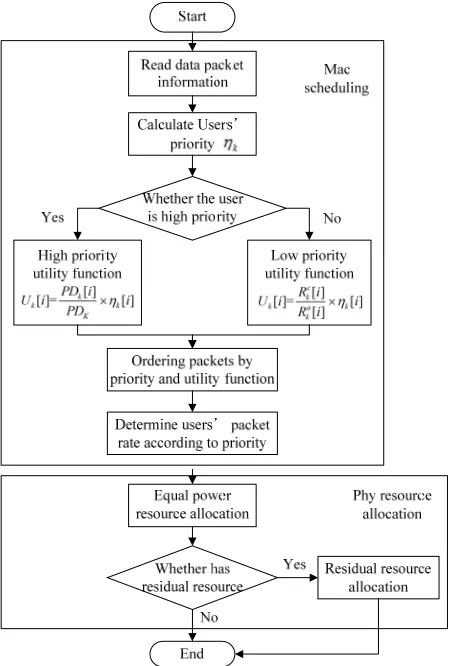
Figure 2. The flowchart of cross-layer resource allocation.
If the system does not have enough sub-carriers to transmit bits of the packets, they are not sent in this OFDM symbol, and the allocation algorithm of the present OFDM symbol finishes. If the allocation can be finished and the system still has sub-carriers to be used, return to the first step.
The flowchart of cross-layer resource allocation on broadband power line communication is shown in Figure 2.
4. Simulation and Analysis
4.1. Traffic Source Model
With the development of broadband power line commu-nication, services hosted on it become diverse increas-ingly. In order to facilitate the analysis, service which has high time delay requirements belongs to real-time service, and others are non-real-time service. Two types of ser-vices are modeled.
[image:3.595.64.282.572.719.2]1 ( T T/ OFF)
(9)
1 exp( T T/ ON)
(10) In which T is the length of one OFDM symbol, OFF
is the average of quiet period, is the average of activation period.
T
ON T
Packets of non-real-time service queue arrive obey the Poisson distribution.
( ) ( )
!
t n e t P N n
n
(11)
In which is the average packets arrival rate of non- real-time service.
In order to ensure the stability of the system, the aver-age capacity of services should not exceed the system’s total transmit capacity. Service source models created using above distributions are shown in Figure 4 and
[image:4.595.67.278.358.720.2]Figure 5.
Figure 3. The real-time service Markov model.
0 100 200 300 400 500 600 700 800 900 1000 0
0.5 1 1.5
Time
uni
tary
dat
a
Two-state Markov
Figure 4. The real-time service model.
0 100 200 300 400 500 600 700 800 900 1000 0.4
0.6 0.8 1 1.2 1.4 1.6 1.8
Time
uni
tar
y
dat
a
Poisson
Figure 5. The non-real-time service model.
4.2. Simulation and Analysis of System Performance
The algorithm simulates in typical power line environ-ment. The following parameters are set as follows: The frequency range is 0-20 MHZ, power spectrum upper is -50-0.8 f (dBm/Hz) and f is in MHz. The number of sub-carriers is 128. Real-time business is corresponding to user 1 and 2 and the maximum delay is 10ms. Its max- imum packet loss rate is 10-3. Non-real-time business is corresponding to user 3 and 4 and its maximum queue length is 600. Its maximum packet loss rate is 10-3. =
0.7. Four users’ average packets arrival rates are: 60 kbps, 60 kbps, 40 kbps and 30 kbps.
This article selects maximum throughput algorithm [7] (MAX/MIN) as the comparison. And the proposed algo-rithm compares and analyses the following factors, such as system throughput, delay and packet loss rate.
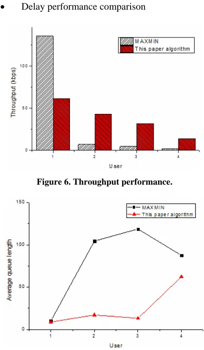
[image:4.595.317.524.367.722.2] Throughput performance comparison
Figure 6 depicts that the MAX / MIN has an uneven distribution. User one has high throughput, but other us-ers throughput is low. This paper algorithm’s throughput matches users’ average packets arrival rates and has high throughput.
Delay performance comparison
Figure 6. Throughput performance.
Figure 7 shows the average queue length of each user. The MAX\MIN has long queue length. It shows that us-ers have higher delay. This paper algorithm has short queue length, which means the delay of packets is short.
Performance comparison of packet loss rate. Statistics show that the packet loss rate of MAX / I is 0.0015. The packet loss rate of this paper algorithm is zero. The algorithm proposed takes the users’ average packets arrival rate into account, improving the packets’ transmission rate. And, the algorithm possessed gets lower packet loss rate and ensures the user's QoS.
5. Conclusions
This paper discusses cross-layer resource allocation on broadband power line communication system and puts for- ward a MAC layer scheduling algorithm based on users’ priority. The algorithm creates different scheduling func-tion between the real-time and non-real-time users in MAC layer, and applies the priority function to divide users into two priorities. Then users are scheduled based on the priority and utility function. In the physical layer, equal power allocation method is used. The simulation results show that the proposed algorithm can take the latency and throughput into account and improve user's QoS.
6. Acknowledgements
This work was supported by National Natural Science Foundation of China (No.51007021) and National Sci-ence and Technology Major Project of the Ministry of Science and Technology of China (No.2010ZX03006- 005-01).
REFERENCES
[1] J. Huang, G. S. Vijay and A. Rajeev, et al., “Joint Sched-uling and Resource Allocation in Uplink OFDM Systems for Broadband Wireless Access Networks,” IEEE J. Se-lect. Areas Commun. Vol. 27, No. 2, 2009, pp. 226-234.
doi:10.1109/JSAC.2009.090213
[2] C. Fan, L. Zhang and W. J. Lian, “A Scheduling Algo-rithm for Guarantying QoS of Streaming Traffic over Mixed Services,” Journal of Bijing University of Posts and Telecommunications, Vol. 30, No. 3, 2007, pp. 75-78.
[3] W. W. L. Ho and Y. C. Liang, “Optimal Resource Allo-cation for Multiuser MIMO-OFDM Systems with User Rate Constraints,” IEEE Trans. Veh. Technol., Vol. 58, No. 3, 2009, pp. 1190-1203.
doi:10.1109/TVT.2008.927721
[4] K. Deb, A. Pratap and S. Agarwal, “A Fast and Elitist Multiobjective Genetic Algorithm: NSGA-Ⅱ,”IEEE Transactions on Evolutionary Computation, Vol. 6, No. 2, 2002, pp. 182-197.
[5] S. Y. Lin and J. S. Huang, “Adaptive Subcarrier Assign-ment and Bit Allocation for Multiuser OFDM System Using Ordinal Optimization Approach,” IEEE Trans. Veh. Technol., Vol. 57, No. 5, 2008, pp. 2907-2919.
[6] H. Hou, W. Zhou, S. Zhou, et al., “Cross-layer Resource Allocation for Heterogeneous Traffics in Multiuser OFDM based on a New QoS Fairness Criterion,” in Proc. VTC, Baltimore, MD, USA, Sept. 2007, pp. 1593-1597.