Performance Analysis of IEEE 802.15.4
M. M. Chandane
Department of Computer Technology, VJTI, Mumbai,
India
S. G. Bhirud
Department of Computer Technology, VJTI, Mumbai,
India
S.V. Bonde
Department of Electronics and Telecommunication, SGGSIE&T, Nanded, India
ABSTRACT
Wireless Sensor Network (WSN) consists of a large population of sensor nodes capable of computation, communication and sensing. Limited storage, processing, and transmission power are inherent limitations of WSN. IEEE 802.15.4 is a new standard, uniquely designed for low rate Wireless Personal Area Network (LR-WPAN), developed for applications that demand low throughput. Main features of this standard are network flexibility, low cost, very low power consumption and low data rate in an ad-hoc self-organizing network. In this paper, performance analysis of IEEE 802.15.4 is performed using Qualnet 4.5. Star topology, multi-hop peer to peer network along with MANET routing protocols such as AODV, DSR and DYMO are used for analysis of Quality of Service (QoS) parameters like throughput, packet delivery ratio, average end-to-end delay, jitter, total energy consumption, and network scalability as the performance metrics. The comparative analysis of result show that AODV outperforms other two in star topology whereas DSR has slightly upper hand in multi-hop topology for varying traffic loads, and in beacon enabled mode.
Keywords
Wireless sensor network, IEEE 802.15.4, Low Rate Wireless Personal Area Network, MANET, self-organizing network, ZigBee, Qualnet4.5.
1.
INTRODUCTION
Over a decade of time, there is a rapid growth in mobile devices and wireless technologies. IEEE 802.11, a wireless communication standard was concerned with features like Ethernet matching speed, complexity to handle seamless roaming, message forwarding, and data throughput of 2-11Mbps. So far, attention was mainly focused on high data rate and relatively long range applications. The growth of mobile devices such as laptops, palmtops, personal digital assistants (PDAs), pocket computers, Bluetooth, pagers, mobile phones, sensors have created a demand for short range, low rate wireless standards. Therefore, IEEE 802.15 working group was formed to create Wireless Personal Area Network (WPAN) standard, intended to focus on low-cost, low power, short range (up to 10 m) and very small size devices. This group has currently defined three classes of WPANs that are differentiated by data rate, battery drain and quality of service (QoS) parameters. The high data rate WPAN (IEEE 802.15.3) also known as ultra wide band (UWB), a standard for high data rate, suitable for multimedia applications that require very high QoS. Medium data rate WPANs (IEEE 802.15.1/Bluetooth) handle a variety of tasks ranging from cell phones to PDA communications and have QoS suitable for voice communication. The low rate WPANs(IEEE 802.15.4/LR-WPAN), known as Wireless Sensor Network (WSN), specifically designed for low cost, very low power consumption, and low data rate in an ad-hoc, self-organizing network[1][2]. WSN demands large number of tiny smart sensors, deployed in an ad-hoc fashion for the
purpose of tracking and surveillance in a terrain through random and dense deployment. Recent advancements in micro-electro mechanical system (MEMS) technology have made it possible to make these components small, powerful, and energy efficient. Very small in size, the sensor nodes are capable of gathering, processing, and communicating information to outside world through intermediate router nodes. Sensor node is the basic building block of a WSN and is a self contained modular low-cost electronic system that consists of three major functional units viz. sensing, computation and communication, packed in a small unit, about 1 inch in diameter. The sensing element monitors a variety of ambient conditions. The computation unit include data analysis and the communication unit consists of RF transmission and reception between different nodes, within the vicinity of the transmission range [3][4]. The basic objective of IEEE 802.15.4 is to support short range applications such as habit monitoring, battlefield surveillance, nuclear, biological, and chemical attack detection, industry automation, home automation and many more [3]. Such applications require a small, low-cost, highly reliable technology that offers long battery life, IEEE and ZigBee alliance [5] are working together to achieve the goal. IEEE 802.15.4 standard focuses on the specification of the lower two layers (physical and data link layer) whereas ZigBee alliance provides upper layers of the protocol stack (from network to the application layer) for interoperable data networking, security services and a WSN application. [6]
This paper is organized as follows: Section II presents the literature survey. Section III gives the brief overview of IEEE 802.15.4. Experimental set-up is given in section IV. Results are discussed in section V and finally, section VI presents the conclusion.
2.
LITERATURE SURVEY
networks. In [8], VOJISLAV B. MIŠIC and JELENA MIŠIC have compared the pertinent features of the two emerging technologies for wireless sensor networks: IEEE Standards 802.15.1 and 802.15.4. In [9], G. Lu, B. Krishnamachari et. al. have provided the performance evaluations of IEEE 802.15.4 MAC in beacon-enabled mode for a star topology. The performance evaluation study revealed some of the key throughput-energy-delay tradeoff, inherent in IEEE 802.15.4 MAC. In [10], Anna Abbagnale et.al. have evaluated the impact of sinks‟ mobility in a wireless sensor network, created using topology formation mechanism provided by the IEEE 802.15.4. In [11], Andrew Wheeler et. al. have described the ecosystem, emerging around ZigBee and the trends in ecosystem, Also highlighted the new areas of activities in ZigBee. In [12], X. Liu et. al. have introduced converge cast communication protocol that overcomes the limitations associated implementation complexity and a lack of robustness in the face of node failures.
3.
OVERVIEW OF IEEE 802.15.4
IEEE and ZigBee alliance have joined hands to develop a complete specification of protocol stack for 802.15.4. IEEE focuses on the specification of the lower two layers of the protocol (physical and Mac layer) that supports for low data rate, low power consumption, and low cost whereas ZigBee works on upper layers of the protocol stack (network, transport, and application layer) that enables interoperable data networking, security services and a range of wireless home and building atomization applications [1]
802.15.4, the new standard defined by IEEE, specifies physical layer (PHY) and medium access control sub- layer (MAC) specification to support highly resource constrained devices with very limited transmission range. Through this standard, global visibility of the devices is achieved using 2.4 GHz band which is a license free industrial scientific medical (ISM) frequency bands. 802.15.4 Supports two PHY options based on the frequency band, both of them are based on direct sequence spread spectrum (DSSS). The supported data rate is 250 kbps at 2.4GHz with offset quadrature phase shift keying (OQPSK) modulation, 40 kbps at 915 MHz and 20 kbps at 868 MHz with binary phase shift keying (BPSK) modulation. Total of 27 channels including single channel between 868 and 868.6 MHz, 10 channels between 902.0 and 928.0 MHz and 16 channels between 2.4 and 2.4835 GHz are allocated in 802.15.4. Receiver sensitivities are −85 dBm for 2.4 GHz and −92 dBm for 868/915 MHz. The main features supported by PHY layer includes activation and deactivation of the radio transceiver, energy detection (ED), link quality indication (LQI), channel selection, clear channel assessment (CCA), and transmitting as well as receiving packets across the physical medium. [6][13] [14]
3.1
PHY layer
The PHY layer provides two services: the PHY data service and PHY management service interfacing to the physical layer management entity (PLME). The PHY data service enables the transmission and reception of PHY protocol data units (PPDU) across the physical radio channel. The PHY provides following features.
3.1.1
Receiver Energy Detection (ED)
It is an estimate of the received signal power within the bandwidth of an IEEE 802.15.4 channel, intended for use by a network layer as part of channel selection algorithm.
3.1.2
Link Quality Indication (LQI)
The LQI measurement is a characterization of the strength and/or quality of a received packet, the use of LQI result is up to the network or application layers.
3.1.3
Clear Channel Assessment (CCA)
It is used to detect the status of medium. CCA is performed using one of the following three methods; Energy above threshold, Carrier sense only, Carrier sense with energy above threshold.
3.1.4
Channel frequency selection
This is intended to select one of the 27 Channels after receiving request from MAC for data transmission.
3.1.5
Activation and deactivation of the radio
transceiver
It turns the radio transceiver into one of the three states i.e transmitting, receiving, or off (sleeping) according to the request from MAC layer. [1][6][14]
3.2
MAC Layer
The MAC layer supports the transmission and reception of MAC protocol data units (MPDU) across the PHY data layer. The communication features of MAC layer are as discussed below. 802.15.4 supports two different devices: a full-function device (FFD) and a reduced-full-function device (RFD). The FFD operate in three modes to serve as a PAN coordinator, a coordinator, or a normal device. FFD can communicate to other FFDs or RFDs, while RFD can communicate only to FFDs.
3.2.1
Beacon generation
In beacon enabled mode, PAN coordinator broadcast beacons periodically to setup the network. The superframe is bounded by network beacons and divided into aNumSuperframeSlots (default value 16) equally sized slots. A coordinator sends out beacons periodically for device synchronization. This primitive also include smacBeaconOrder and macSuperFrameOrder parameters that determine the duration of the beacon interval and the duration of the active and inactive portions of the superframe.
3.2.2
Device synchronization
In beacon-enabled mode, PAN coordinator broadcasts beacons periodically to synchronize the attached devices. It is useful for data polling, and energy savings.
3.2.3
Carrier sense multiple access with collision
avoidance (CSMA-CA
802.15.4 uses CSMA-CA algorithm for channel access and collision avoidance. However, request-to-send (RTS and clear-to-send (CTS) mechanism is eliminated due to low data rate consideration in LR-WPANs.
3.2.4
Guaranteed time slot (GTS)
In LR-PAN, The power saving mechanism is provided through the beacon-enabled superframe. In this paper, we focus on the performance analysis of beacon-enabled mode of IEEE 802.15.4 for QoS parameters with star topology and peer to peer multi-hop topology. Figure 1 shows the structure of superframe. For beacon enabled mode, the beacon frame is sent in the first slot of each superframe otherwise for non beacon enabled mode coordinator turn off the beacon transmissions. Superframe is divided into two parts: an active portion and an inactive portion. The active portion with 16 time slots is subdivided into three parts: a beacon, a contention access period (CAP), and a contention free period (CFP). The beacon is transmitted by the coordinator at the start of slot 0 in every superframe, and the CAP follows immediately after the beacon. In CAP, a slotted CSMA/CA algorithm is used for devices to access the channel and to transmit non-time-critical messages and MAC commands. For 250kbps, 2.4GHz frequency, the duration (also called beacon interval or BI) of a superframe ranges from 15ms to 251.3s corresponding to SO=0 to14. The coordinator and devices can communicate with each other during the active period and enter the low-power phase during the in-active period. This feature is specifically useful for WSN applications, where energy consumption and network lifetime are main concern [13].
GTS GTS Inactive
[image:3.595.49.278.345.516.2]0 1 23 4 5 6 7 89 101112 13 14 15
Figure 1: Super Frame Structure of IEEE 802.15.4
The duration of different portions of the superframe are described by the values of macBeaconOrder and macSuperFrameOrder. The macBeaconOrder describes the interval at which the coordinator shall transmit its beacon frames. The beacon interval BI is related to the macBeaconOrder, BO, as follows:
BI = aBaseSuperFrameDuration*2BO, 0 ≤ BO ≤ 14.
The superframe is ignored if BO = 15. The value of macSuperFrameOrder describes the length of the active portion of the superframe. The superframe duration, SD, is related to macSuperFrameOrder, SO, as follows:
SD =aBaseSuperFrameDuration*2SO, 0 ≤ SO ≤ 14.
If SO = 15, the superframe should not remain active after the beacon. The fact that BO=SO assures that no inactive part of the superframe is present. A low value of this parameter implies a great probability of collisions of beacons frames as these would be transmitted very frequently by coordinators. On the contrary, a high value of the BO introduces a significant delay in the time required to
perform the MAC association procedure since channel duration which is a part of association procedure is proportional to BO.
4.
EXPERIMENTAL SETUP
The main objective of this simulation study was to evaluate the performance of 802.15.4 for different reactive routing protocols like AODV [16], DSR [17] and DYMO [18] for star and multi-hop peer to peer network with varying traffic loads. The simulations have been performed using Qualnet version 4.5 [15]. MAC and Physical layer protocol used for experimentation are IEEE 802.15.4. Constant bit rate (CBR) data traffic is applied over User Datagram Protocol (UDP) connection between source and destination with average packet rates: 0.1 packets per second (pps), 1 pps, 2 pps, 5 pps and 10 pps, 15 pps are used. Two different topologies are used: (1) Star Topology with 15 CBR and (2) Multi-hop network
In simulation model, a star topology (Figure 2) is created with one PAN coordinator, 50 RFDs, and 15 CBR applications, uniformly deployed in an area of 500m x 500m. PAN coordinator is placed at the centre of the simulation area. Only the upward traffic from RFD‟s to PAN coordinator are considered in the simulation, that suits most of the WSN applications like automation industry where a large number of devices communicate to a single sink server for data delivery. All RFD‟s are placed within the transmission range of PAN coordinator. A Multi-hop network (Figure 3) is created with four different variations (1 hop, 2 hop, 3 hop, and 4hop networks). Co-coordinator devices are placed in between PAN and RFDs to work as routers. Distance between any pair of node is kept as 200m. QoS parameters are analyzed for varying traffic load, number of hops. The results are shown in figures from 4 to 14. The simulations parameters are shown in table1
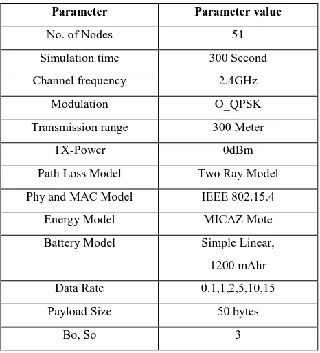
Table 1. Simulation Parameters
Parameter Parameter value
No. of Nodes 51
Simulation time 300 Second
Channel frequency 2.4GHz
Modulation O_QPSK
Transmission range 300 Meter
TX-Power 0dBm
Path Loss Model Two Ray Model
Phy and MAC Model IEEE 802.15.4
Energy Model MICAZ Mote
Battery Model Simple Linear,
1200 mAhr
Data Rate 0.1,1,2,5,10,15
Payload Size 50 bytes
Bo, So 3
Following performance metrics are used for the analysis study of routing protocols for Ad-Hoc Network
SD =aBaseSuperFrameDuration*2SO Symbols
BI = aBaseSuperFrameDuration*2BO Symbols
CAP CFP
Beacon
(Active)
[image:3.595.315.548.459.716.2]Throughput: It is defined as the total number of packets received at the sink node divided by the simulation time. It is generally measured in bits/Sec (bit/sec or bps).
Network lifetime: It is defined as the time elapsed until the first node (or the last node) in the network depletes its energy (dies).
Packet Delivery Ratio (PDR): PDR is defined as the number of packets received at sink node divided by the number of packets sent by the source node.
Average End-to-End delay: It indicates the length of time taken for a packet to travel from the source to destination. Delays due to route discovery, queuing, propagation and transfer time are included in the delay metric. It indicates the average data delay an application experiences during transmission of data.
Average Jitter: Jitter is the variation time in the packet arrival. It is different from the delay and caused due to congestion, topology change etc. in network. It is expected to be low for better performance in ad-hoc networks. It becomes a matter of concern if it is more than the threshold value which is different for each type of transmission as data, voice or video.
Energy Consumption (mJoule): This is the amount of energy consumed by MICAZ Mote devices during the periods of transmitting, receiving, idle and sleep. The unit of energy consumption used in the simulations is mJoule.
Percentage of time in Sleep mode: This parameter is indirectly relates to the duty cycle. The more is the percentage of time in sleep mode, the less is the duty cycle .It is mainly useful in WSN applications which demand low duty cycle.
5.
RESULTS AND DISCUSSION
This section presents the simulation results of various metrics, for performance evaluation of 802.15.4 for star topology using reactive routing protocols such as ADOV, DSR and DYMO with varying data rate and scalable network.
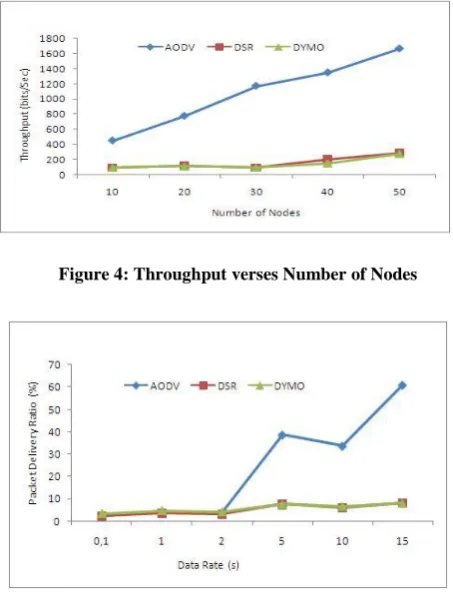
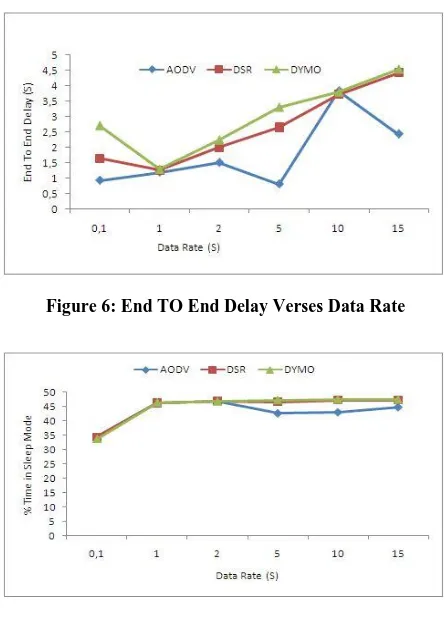
Figure 4 shows the throughput for varying number of nodes. The successful Packet delivery is observed with increasing MAC based CBR traffic load over UDP. It is observed that AODV performs better than both DSR and DYMO. Packet delivery ratio with varying data rate is shown in figure 5. For all types of traffic load, AODV has high PDR than other two protocols. However towards low data rate i.e. from 5 to 15, The PDR of AODV is increased significantly from 40% to 65%. Figure 6 shows the performance of average end-to- end delay for different traffic loads. The average end- to- end delay of a packet depends on delays at each hop comprising of queuing, channel access and transmission delays, the number of hops and route discovery latency. The overall average end-to-end delay performance of AODV is better than DSR and DYMO. The average end to end delay is almost same for all three protocols at data rate of 1 PPS. Figure 7 presents the performance of percentage of time in sleep mode for varying traffic loads. Figure 7 clearly shows that for high data rate, all three protocols have almost same duty cycle. Towards low data rate, DSR and DYMO have slightly lower duty cycle, in this aspect these two protocols are doing better than AODV.
1 Hop 2 Hop PAN COORDINATOR
Coordinator
RFD
3 Hop 4 Hop
Figure 3: Multi-Hop Topology
[image:4.595.316.543.368.669.2] [image:4.595.57.281.416.743.2]Figure 5: Packet Delivery Ratio Verses Data Rate Figure 4: Throughput verses Number of Nodes
Following section presents the evaluation of 802.15.4 for multi-hop network using reactive routing protocols.
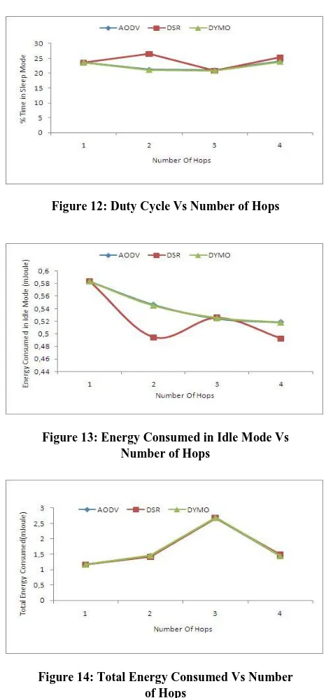
[image:5.595.309.544.72.749.2]Figure 8 shows the throughput for varying number of hops. It is observed that performance of all three protocol decreases linearly over number of hops however DSR has slightly upper hand than other two for 4-hop topology. Figure 9 shows the performance of average end-to- end delay for different number of hops. The overall average end-to-end delay performance of the AODV is much better than DSR however DYMO has almost similar behavior as that of AODV. Figure10 Shows the jitter with varying number of hops, it is observed that for 1, 2 and 4 hop network, jitter for all protocol is almost same whereas for 3-hop network it is high for DSR as compared to other two protocols. Packet delivery ratio with varying number of hops is shown in figure 11. Up to 3 hop networks, all three protocols has almost same PDR however for 4 hop network, DSR shows superiority over other two. Figure 12 presents the performance of percentage of time in sleep mode for varying number of hops. It is observed that with the increasing number of hop, duty cycle of DSR increases as compared to AODV and DYMO. Figure 13 shows that for all three protocols, the energy consumption in idle mode decreases linearly with the increase in number of hops. Specifically for DSR, it is very low for 2-hop and 4hop network as DSR has high duty cycle. The performance of total energy consumption of all three routing protocols for varying number of hops is shown in Figure 14. The total energy consumption is the energy consumption in transmission, reception and idle mode. The total energy consumption of three routing protocols is almost same for all cases.
Figure 6: End TO End Delay Verses Data Rate
Figure 7: Duty Cycle Verses Data Rate
[image:5.595.57.281.73.394.2]Figure 16. Duty Cycle Vs Number of Hops Figure 8: Throughput Vs Number of Hops
[image:5.595.310.543.76.370.2]Figure 9: End To End Delay Vs Number of Hops
Figure 10: Jitter Vs Number of Hops
[image:5.595.312.543.385.723.2]6.
CONCLUSION
A simulation based performance analysis of quality of service parameters for WSN based on IEEE 802.15.4‟s star and multi-hop topology in beacon enabled mode is investigated. Qualnet 4.5 is used for the analysis of network performance parameters with reactive routing protocols like AODV, DSR and DYMO for varying traffic loads and network scalability.
From the analysis and simulation results of star topology of our study, it can be concluded that the performance of reactive routing protocol depends upon the scenario. In general AODV performs better than DSR and DYMO. Specifically, AODV shows its superiority over other two protocols for low traffic loads, which is best suitable for WSN applications; but at high traffic loads all three routing protocols have nearly same behavior.
In multi-hop communication, all three protocols have almost similar behavior however with the increasing number of hops; DSR has slightly better performance in terms of PDR and throughput compared to other two. This performance of DSR may be because of its source routing based aggressive caching approach.
However, the overall performance of these three protocols on IEEE 802.15.4 is not quite good. The major reason for performance degradation could be their design consideration. These protocols are specifically designed for mobile ad-hoc network to deal with frequent topology changes. WSNs have very high resource constraints in terms of memory, processing, and transmission power. To meet these challenges, new routing protocols needs to be designed for WSN, by considering key features of reactive routing protocols, which are still performing well for static Wireless Sensor Networks.
7.
REFERENCES
[1] Sinem Coleri Ergen, ZigBee/IEEE 802.15.4 Summary, September 10, 2004
[2] Jianliang Zheng and Myung J. Lee, Will IEEE 802.15.4 Make Ubiquitous Networking a Reality ? A Discussion on a Potential Low Power, Low Bit Rate Standard, IEEE Communications Magazine, June 2004.
[3] Ian F. Akylidiz, Weilian Su, Yogesh Sankarasubramaniam and Erdal Cayirci. Wireless Sensor Network: A Survey on Sensor Networks. IEEECommunications Magazine, 40(8); pp. 102-114, August 2002.
[4] Suraiya Tarannum, B Aravinda, L Nalini, K.R. Venugo-pal, and L. M. Patnaik, Routing Protocol for lifetime Maximization of Wireless Sensor Networks, IEEE Explore, PP.401-406, 2006.
[5] ZigBee Resource: http://www.zigbee.org
[6] J. Zheng and Myung J. Lee, "A comprehensive performance study of IEEE 802.15.4," Sensor Network Operations Book, IEEE Press, Wiley Interscience, Chapter 4, pp. 218-237, 2006.
[7] Wilson T.H. Woon and T.C. Wan, Performance Evaluation of IEEE 802.15.4 Ad Hoc Wireless Sensor Networks: Simulation Approach, IEEE Conference on Systems, Man and Cybernetics, PP1443-1448, October 2006
[8] VOJISLAV B. MIŠIC and JELENA MIŠIC, Sensing with One or with Four? A Comparison of Two IEEE 802.15.x Protocols for Use in Sensor Networks
[9] G. Lu, B. Krishnamachari and C.S. Raghavendra ,“Performance evaluation of the IEEE 802.15.4 MAC for low-rate low power wireless networks," in Proceedings of the 23rd IEEE International Performance Computing and Communications Conference (IPCCC '04), Pages 701-706, Phoenix, Ariz, USA, April 2004.
[image:6.595.49.282.75.573.2][10] Anna Abbagnale, Emanuele Cipollone, Francesca Cuomo, A case study for evaluating IEEE 802.15.4 wireless sensor network formation with mobile sinks, IEEE ICC, 2009.
Figure 12: Duty Cycle Vs Number of Hops
Figure 13: Energy Consumed in Idle Mode Vs Number of Hops
[11]Andrew Wheeler, Ember Corporation, Commercial Applications of Wireless Sensor Networks Using ZigBee, IEEE Communications Magazine, pp 70-77, April 2007
[12]X. Liu, C. Leckie,S. K. Saleem, Performance Evalua-tion of a Converge-cast Protocol for IEEE 802.15.4 Tree-Based Networks, IEEE ISSNIP, 2010
[13]Sanatan Mohanty, Dr.S.K.Patra, Quality of Service Analysis in IEEE 802.15.4 Mesh Networks using MANET, Second International conference on Computing, Communication and Networking Technologies, IEEE, 2010.
[14]IEEE Standard, Part 15.4: Wireless Medium Access Control (MAC) and Physical Layer (PHY) Specifications for Low-Rate Wireless Personal Area Networks (WPANs), IEEE Std 802.15.4™-2006
[15] QualNet Simulator: http://www.scalable-networks.com
[16] Charles E. Perkins and Elizabeth M. Royer, “Ad Hoc On-Demand Distance Vector Routing,” in Proceedings of the 2nd IEEE Workshop on Mobile Computing Syslems and Applications, Feb. 1999, pp. 90-100.
[17] David B. Johnson and David A. Maltz, „„Dynamic source routing in adhoc wireless networks,” in Mobile computing, T. lmielinski and H. Kmh, Eds, Kluwer Academic, 1996, ch.5