2016 Joint International Conference on Artificial Intelligence and Computer Engineering (AICE 2016) and International Conference on Network and Communication Security (NCS 2016)
ISBN: 978-1-60595-362-5
Study on the Sensitive Mechanism of Fluidic Gyroscope
Based on Fluid-solid Coupling
Xing-Yuan CHANG
1,a,*, Lin-Hua PIAO
1,
Lei DUAN
1, Hao-Liang DONG
11Sensors Technology Research Centre, Beijing Information Technology Institute, Beijing, China
*Corresponding author
Keywords: Fluid-Solid Coupling, Fluidic Gyroscope, Sensitive Mechanism, Sensitive Element.
Abstract. Fluid-solid coupling simulation is carried out for the sensitive mechanism of fluidic gyroscope. Based on ANSYS and CFX load transfer of fluid-solid coupling technique to calculate the distribution of flow velocity at heat resistance wires of this gyroscope sensitive element under different input angular velocity. The calculation results show that the flow velocity of the two symmetrical thermal resistance wires is equal at rest; the offset of flow velocity is proportional to the size of the angular velocity of 0°/s to 60°/s. With the increase of the angular velocity, the flow velocity of the two symmetrical thermal resistance wire is also increased. Analysis of fluid-solid coupling provided an effective way for fluidic gyroscope optimization design.
Introduction
Fluidic gyroscope can be applied in rugged environment with the virtue of supporting high overload and low cost etc [1]. General fluidic gyroscope is completely airtight and airflow can just cycle in the airtight cavity. It requires a high structure precision and big bulk, which restrict it’s application and development. There are inlet and outlet in fluidic gyroscope. The airflow, orientation movement forming from inlet to outlet, is cycling periodically in open cavity under the driving of piezoelectric pump. Previous FEA of fluidic gyroscope, such as literature [2-3] etc., are built up based on flow structure. Vibration of solid load at flow boundary directly as in-built condition. It can not simulate accurately for fluidic gyroscope. As the result, it’s difficult for it to express the distribution condition of airflow velocity inside of the fluidic gyroscope. This paper study on the flow velocity distribution of inside of the fluidic gyroscope sensing element, using fluid-solid coupling technique the first time, through 3D modeling and interaction between fluid and solid. Not only can it optimize the structure of the fluidic gyroscope, but also can it shorten the design period.
Structure Principle
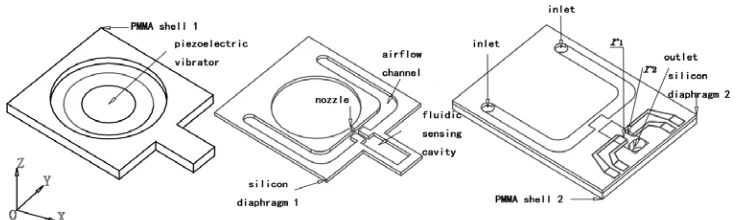
[image:1.612.132.500.614.724.2]The shape profile of Fluidic gyroscope sensing structure is shown in figure 1.
It consist of piezoelectric diaphragm PMMA shell, silicon diaphragm, airflow channel, fluidic sensing cavity, nozzle and thermal resistance wire, which is assembled ordinal superposition bonding from left to right. The piezoelectric pump, composed of piezoelectric diaphragm, PMMA shell and nozzle, driven by which the air flows in airflow channel. Orientation movement, forming from inlet to outlet, generate fluidic bound, what is flowing to two parallel symmetrical thermal resistance wire inside of fluidic sensing cavity. The thermal resistance wire is made of Tungsten. The flow flowing through the centre of two parallel symmetrical thermal resistance wire will make
deflection because of the Coriolis Effect when the angular rate about Z axis is applied. This
result in the reverse cooling effect between two symmetrical thermal resistance wire r1,
2
r .Correspondingly, the value of thermal resistance wire changes inversely. The variation of
resistance value convert to the variation of output voltage u by the Wheatstone half-bridge, as
[image:2.612.161.462.238.387.2]shown in figure 2.
Figure 2. Operational principle of fluidic gyroscope.
Physical Model
[image:2.612.156.465.555.704.2]This paper describe the simulation based on load transfer of fluid-solid coupling. As shown in figure 3, we simplify the fluidic gyroscope as two part, piezoelectric diaphragm and airflow channel. Piezoelectric diaphragm consist of piezoelectric ceramics and elastic placode. We load alternating voltage to the upper surface of piezoelectric ceramics. Then, coupling surface on the downer surface of elastic placode achieves the load transfer between fluid and solid. Additional, airflow in the channel is the air under oridinavx temperature and pressure. We assumed that pressure of inlet and outlet are standard atmospheric pressure.
The Fluid-Solid Coupling Solution
We built up piezoelectric vibrator model and fluid are model in ANSYS and CFX and then set up the coupling surface between the two models. Finally, we solve the problem by MFX multiphysics solver.
We upload dat. and def. document generated previously in the MFX multiphysics solver simultaneously. There are some in-built conditions. We conduct structure mechanics analysis in ANSYS before fluid-calculated analysis in CFX. The displacement information transmitting from ANSYS to CFX and the stress analysis moving to opposite direction are the coupling surface load transfer. Finally, we set up initial time, terminal time, coupling time and the number of iteration, 100.
Calculated Results and Discussion
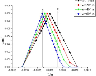
We simplify the parallel symmetrical thermal resistance wire as line L that connecting centres of two thermal resistance wire. When different angular rate are applied, the flow velocity distribution
of L is shown in figure 4.
-0.0015 -0.0010 -0.0005 0.0000 0.0005 0.0010 0.0015 0.000 0.001 0.002 0.003 0.004 0.005 0.006 0.007 0.008 v/ m s-1 L/m at rest
=20° /s
=40° /s
=60° /s
r1 r2
[image:3.612.231.397.284.415.2]
Figure 4. Flow velocity distribution along L.
Distances between L and nozzle, and of two thermal resistance wires are 5.5mm and 0.7mm, respectively. The flow velocity flowing through the two parallel symmetrical thermal resistance wire is equal at rest, while the velocity
s m V
Vr1 r20.0048 / (1)
When angular rate of 20°/s is applied, the flow velocity of r1, r2:
s m
Vr10.00524 / (2)
s m
Vr2 0.00377 / (3)
respectively. Obviously, difference between them is 0.00147m/s; when angular rate of 40°/s is applied, the flow velocity:
s m
Vr10.00582 / (4)
s m
respectively. Obviously, difference between them is 0.0032m/s; when angular rate of 600°/s is applied, the flow velocity:
s m
Vr10.0065 / (6)
s m
Vr2 0.00124 / (7)
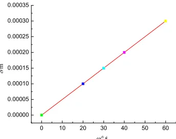
respectively. Obviously, difference between them is 0.00526m/s. When the angular rate about Z axis is applied, the airflow velocity of two parallel symmetrical thermal resistance wire are different and the difference is increasing with the increasing angular rate. Thus, within the scope of the angular rate of 0°/s to 60°/s, this result in the increasing difference of current flowing through two thermal resistance wire. Further, the Wheatstone half-bridge get unbalanced and the output signal is a voltage corresponding to angular rate. Figure 5 describes the relational schema between angular rate and airflow offset. Obviously we can find that the offset of airflow velocity is proportional to angular rate when the distance and time-averaged velocity are constant.
0 10 20 30 40 50 60 0.00000
0.00005 0.00010 0.00015 0.00020 0.00025 0.00030 0.00035
/m
[image:4.612.214.386.284.420.2]/s
Figure 5. Relational schema between angular rate and airflow offset.
Conclusion
The core sensing element of fluidic gyroscope is the two parallel symmetrical thermal resistance wire. They have the same performance that it heats itself when in charge. Thus, the fluidic flow through the symmetrical centre of two thermal resistance wire when adscitious angular rate is not applied. The thermal exchange value between two thermal resistance wire and fluidic is equal.
Similiarly, both of resistance and cooling effect of r1, r2 are same. Thus result in that the
Wheatstone bridge is balanced and that output voltageu is zero. When adscitious angular rate is
applied, the fluidic flowing through centre of two parallel symmetrical thermal resistance wire will
preform deflection because of Coriolis Effect. Thus, fluidic velocity flowing through r1, r2 are
different, which result in the reverse cooling effect on two symmetrical thermal resistance wire. Accordingly, the value of thermal resistance wire can change reversely. The Wheatstone bridge gets unbalanced because of the difference of two resistance. Finally, the output voltage signal is a voltage corresponding to adscititious angular rate. The above is the explanation of sensitive mechanism of fluidic gyroscope based on fluidic-solid coupling.
Acknowledgement
Control Technology funded by Ministry of Education Key Laboratory.graduate student innovation projects of Beijing Information Science and Technology University.
Reference
[1] Fuxue Zhang, Modern piezoelectric (Part ii) [M], BeiJing: Science Press, 2002.
[2] Linhua Piao, Bin Zhang, Jinduo Zhang, Fuxue Zhang, FEA of Sensitive Mechanism of Piezoelectric Fluidic Angular Rate Sensor, Piezoelectric & Acoustooptics, J, 27(3) 309-301.