2016 Joint International Conference on Artificial Intelligence and Computer Engineering (AICE 2016) and International Conference on Network and Communication Security (NCS 2016)
ISBN: 978-1-60595-362-5
Design and Implementation of Stable Gait for Bipedal Robot
Lei ZHANG
1,a, Han-Yu ZHU
2,b,*, Xiao-Kai FENG
3,cDepartment of Engineering, Ocean University of China, Qingdao, Shandong, China
a[email protected], b[email protected], c[email protected]
*Corresponding author
Keywords: Biped Robot, Gait Planning, Three-Dimensional Inverted Pendulum, Implementation.
Abstract. This paper presents an optimized method of gait planning for a small biped humanoid robot which developed independently. The method is based on the research of the gait generation patterns for biped robot and analyses the gait generation method which based on three dimensional linear inverted pendulum and the relationship between the COG height, initial velocity, step length and the walk cycle. We carry on the design of bipedal robot gait and realize the stable walking of robot. The simulation and experimental results have confirmed the feasibility of this method.
Introduction
Bipedal walking is one of the most basic characteristics of the humanoid robot. We called the robot motion planning the gait planning [1]. The humanoid robot has many degrees of freedom and complex dynamic characteristic [2-3]. If we adopt appropriate model, it will be more concise and fast.
This paper presents a simple and practical method of gait planning, which is suitable for humanoid robots with the same structure of legs. We adopt the characteristics of parameter of the developed small biped humanoid robot, and validate our proposed method by dynamic biped walking task.
Robotic Model
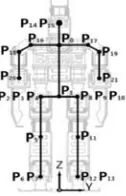
[image:1.612.278.341.554.652.2]As shown in Figure 1, the DOF of the prototype is distributed as follow: 12 DOF for legs, 6 DOF for arms, 2 DOF for head. In addition, we define two virtual joints to facilitate our research [4-5]. Digital servo AX-12A is adopted as the joint driver, which has high control accuracy and real-time status information feedback.
Figure 1. The robotic prototype.
Design of Dynamic Walking
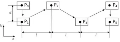
In practice, we specify the location of the steps directly so that we can design the gait better [6]. As shown in Figure 2, we set the robotic step length as s, step width as d, P0 ~ P5 as the footholds.
[image:2.612.209.405.120.189.2]
Figure 2. Sketch on foot.
Establishment of Model
[image:2.612.340.512.274.416.2]We analyze the robot based on the three dimensional linear inverted pendulum models. Model is shown in figure 3.
Figure 3. The robot model. Figure 4. Inverted pendulum model.
The ‘r’ is the distance between protection and support. The COG is only affected by stretching force f and gravity. Equations of motion are as follows.
Mx x/r f (1)
My y/r f 2
Mz f Mg 3
The M is the mass of the inverted pendulum and x, y, z is the coordinates of the COG. Keep the COG height unchanged. We get the equations of the COG in the horizontal plane.
x x 4
y y 5
[image:2.612.105.271.275.425.2]The z is the COG height. The p∗ is the coordinates of the foothold and the x is the coordinates
of current position. The relationship between them is as follows
x x p∗ 6
The solution of differential equation (6):
x t x p∗ cosh T x sinh p∗ 7
x t ∗sinh t T x cosh t T 8
x , x are the initial conditions of the nth step, the relationship between the foothold
p∗ and the final conditions of the nth step is as follows:
x x
C T S
S/T C
x x
1 C
S/T p∗ 9
In eqn. (9), T , C ≡ cosh ,S ≡ sinh .
In order to choose the foothold properly, an error evaluation function is defined: N ≡ a x
x b x x
x , x are the expected foothold position and speed, respectively. x , x are the final conditions
of the nth step, a and b are positive weighted factors.
According to ∂N/ ∂p∗ 0, we can get the foothold p∗that can make error evaluation function
minimal. Gait Analysis
[image:3.612.96.512.578.687.2]In eqn. (7), (8), (9), the realization of the gait is closely related to the following variables: COG. Walk cycle. Step length. Initial velocity and Parameter a & b. We study by controlling variable method combined with the prototype parameter. The main performance parameters of the prototype are shown as follow:
Table 1. Robot parameter.
Name Parameter Name Parameter
Height 450mm Weight 1.8kg
Height of COG 200mm Degrees of freedom 20 Height of hip joint 219mm Height of knee joint 126mm Height of ankle joint 33mm Leg length 186mm
Foot width 62mm Foot length 104mm
Step width 74mm Step length 30mm
1) We keep the step length unchanged. The relationship between the Initial velocity and the COG&Walk cycle is shown in figure 5.
too, but the decrement is less; The walking stability will be increased by reducing the height of the COG appropriately during walking process, which would not affect the experimental results.
2) We keep the COG height unchanged. The relationship between the Initial velocity and the step length&Walk cycle is shown in figure 6
[image:4.612.95.519.395.642.2]The figure shows, under the condition of the COG height, with the increases of walk cycle, the initial velocity decreased; with the increases of the step length, the initial velocity increased.
Figure 5. The relationship between walk cycle,
COG height and initial velocity. Figure 6. the relationship between walk cycle, step-length and initial velocity.
3) Now we study the foothold p∗ impact on the state of the robot. Considering the previous
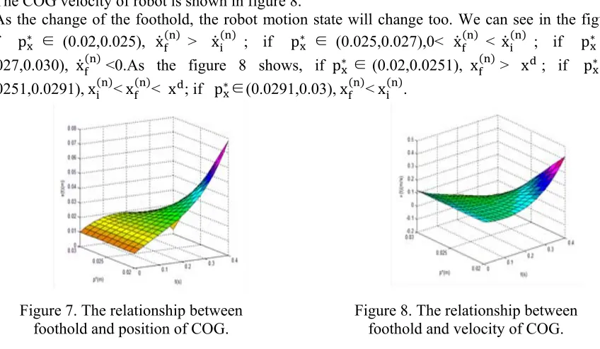
analysis, we set the COG height as 0.2m,step length as 0.03m,walk cycle as 0.4s and the initial velocity is 0.12m/s. We study the motion of the robot one cycle from 0.01m to 0.04m and p∗ is
from 0.02m to 0.03m. The COG position of robot is shown in figure 7. The COG velocity of robot is shown in figure 8.
As the change of the foothold, the robot motion state will change too. We can see in the figure 7,if p∗ ∈ (0.02,0.025), x > x ; if p∗ ∈ (0.025,0.027),0< x < x ; if p∗ ∈
(0.027,0.030), x <0.As the figure 8 shows, if p∗ ∈(0.02,0.0251), x > x ; if p∗ ∈
(0.0251,0.0291), x < x < x ; if p∗∈(0.0291,0.03), x < x .
Figure 7. The relationship between foothold and position of COG.
Figure 8. The relationship between foothold and velocity of COG.
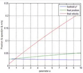
4) As the analysis of the 3), the footholds produce a great impact on the robot motion. Parameter a and b are positive weighted factors, which have an effect on the choice of the foothold. Considering the previous analysis, we set the COG height as 0.2m, step length as 0.03m, walk cycle as 0.4s. We set the initial position, velocity as 0.01m,0.12m/s and final position, velocity as 0.04m,0.12m/s .For convenience, we set b as 1, a as a certificate.
We set the initial position, velocity as 0.01m,0.12m/s. The relationship between the final state and the target state is shown in figure 10.
[image:5.612.123.268.151.278.2]We can see in the figure, this method cannot fully realize the foothold specified by walking parameters. And with the deviation of the designated target state, error will be larger. So, we can't set foot parameters and target state at will actually. However, due to the equation (6) can guarantee error close to zero, the robot can approach the foothold specified when walk stable.
[image:5.612.362.501.158.270.2]Figure 9. The relationship between foothold and parameter.
Figure 10. The relationship between foothold and target location.
We can get the following gait planning algorithms:
1. Set the gait parameters s , s , walk cycle T , initial foothold p∗,p∗ p , p ,
initial position of COG x, y ;
2. T ≔ 0, n ≔ 0;
3. If the time is end, skip to step 9;If not, carry on the integral to the equation ;
4. T ≔ T T , n ≔ n 1;
5. Compute the next foothold;
6. Calculate the next target location x , y according to the equation; 7. Calculate the target state x , x , y , y ;
8. Adjust the foothold according to the equation; 9. Return to step 3;
10. According to the COG trajectory and foothold, we calculate the joint Angle by the method of inverse kinematics.
Experimental Verification
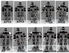
According to the prototype parameters and simulation analysis, we determine the scope of variables: Walk cycle0.2~0.8s; COG height0.15~0.21m;Step length 0.02~0.08m. We select step length as 0.03 m, width as 0.036 m, COG as 0.2 m, Walk cycle as 0.4 s, initial velocity as 0.12 m/s. The COG trajectory of the robot relied on the proposed gait planning method is shown in Figure 11.
The walking process of the prototype is shown in Figure 11. We can figure out that the proposed gait planning method is effective.
[image:5.612.147.259.626.736.2]Figure 12. the walking process of the prototype.
Conclusions
The proposed gait planning method is efficient for off-line planning of biped walking robot, which provides basis method and stable condition for robot dynamic walking process. Moreover, it is beneficial to modify the mechanical structure of robot depended the analysis of robot basis parameters according to the proposed method. Furthermore, we can achieve a stable walking process with the information of gestures, pressure sensors and online modification. This method can also be applied to other biped robot with similar leg structure.
Acknowledgement
This work was supported by the Major Program of Natural Science Foundation of China (No.51279185).
References
[1] Yu Zhiwei. “Study on humanoid gait planning and stability of biped robot” PhD diss., Harbin Engineering University, 2008.
[2] Y. Sakagami, et al. “The intelligent ASIMO: system overview and integration”. Proc. IEEE-RSJ Int. Conference on Intelligent Robots and Systems, Vol. 3, pp. 2478-2483, 2002.
[3] G.R. Mettam, L.B. Adams, How to prepare an electronic version of your article, in: B.S. Jones, R.Z. Smith (Eds.), Introduction to the Electronic Age, E-Publishing Inc., New York, 1999, pp. 281-304.
[4] Tian Yang. “Design and Development of the Small Biped Humanoid Robot” MEng diss., Ocean University of China, 2013.
[5] Zhe Qiu, Lei Zhang, Yang Tian, Xiaokai Feng, Shengyuan Zhang. “An Optimized Design of Humanoid Robot Distributed Control System”. Applied Mechanics and Materials, 2014, 541: 1043-1048.