--...-
~- - - -
-
-~-- -~-- -~--
-
- .---IBM
S/390®
Integrated Server 3006
- - - - -
----_
-
-
- ---
.
-Service Guide
-- -- -- --
- - -
-
-
--
-
---IBM
S/390®
Integrated Server 3006
- - - - -
--_.-
-
-
-
---Service Guide
ModelBOl
Note! ---~~~---~ ' .. :-. Before using this information and the product it supports, ~~. sure to read the general information under "Notices" on page xi.
Second Edition (May 1999)
This edition, SY24-6161-01, applies to the IBM System/390® Integrated Server version 3.0 and licensed internal code version 2.10 and to all subsequent releases of this product until otherwise indicated in new editions or Technical Newsletters.
Changes are made periodically to the information h~rein; any such changes will be reported in subsequent revisions or Technical Newsletters.
Publications are not stocked at the address given below. U.S. customers can order publications by calling the IBM Software Manufacturing Solutions at 1-800-879-2755. Outside the U.S., customers should contact the IBM branch office serving their locality.
A form for readers' comments is provided at the back of this publication.
When you send information to IBM, you grant IBM a nonexclusive right to use or distribute the information in any way it believes appropriate without incurring any obligation to you.
© Copyright International Business Machines Corporation 1999. All rights reserved.
Note to U.S. Government Users - Documentation related to restricted rights - Use, duplication or disclosure is subject to restrictions set forth in GSA ADP Schedule Contract with IBM Corp.
Contents
)
© Copyright IBM Corp. 1999
Notices
Electronic Emission Notices Trademarks . . . . ~tatement of Limited Warranty
Safety . . . . Safety Notices . . . . Laser Safety Information
Laser Compliance
World Trade Safety Information
Preface . . . . Who Should Use This Guide How This Book Is Organized
Chapter 1. START
Problem / Service Activity Start List
Chapter 2. Solving Problems OS/2 Problems . . . . Sequence of events from a power up
Chapter 3. P/390 Processor Card Processor Unit Problem/Action List
· . . . . xi
· . . . . xi
· . . . . xii
· . . . xiii
· . . . xvii
· . . . xvii
· . . . xvii
· . . . xvii
· . . . xviii
xix xix xix 1 1 . . . 3
3 3 . . . 7
7 Description . . . . . . . .. . . . . . . 7
Installing P/390 Hardware and Software . . . " . . . 8
Diagnostics . . . . . . 8
Procedure . . . . . . . 9
STOPPED and DOWN Displayed on the System/390 HI Activity Display 10 P/390 Error Messages . . . 11
AWS Message Format . . . 11
Chapter 4. PCI/ISA BUS and Adapters . . . . Start of Repair for PCI-ISA Bus and Adapters . . . . Description of the PCI/ISA BUS . . . . Maximum Configurations . . . . Adapter Plugging Rules for PCI/ISA slots PCI/ISA Slots . . . . SBC/PCI/ISA Bus Structure - Logical View SBC/PCI/ISA Bus Structure - Physical View Solving Adapter Problems PCI Bus Isolation . . . . Token-Ring Adapter Adapter LEDs and Labels Labels . . . . LEOs . . . . Adapter Communication Problems Adapter Cable . . . . Configuration Settings . . . . . NDIS 2 Device Driver Messages 13 13 13 . . . 13
iv
Service GuideDiagnostics . . . EtherJet PCI Adapter
Diagnostic LEOs
Common Problems and Solutions
Diagnostics . . . . Adapter Address . . . . Fast Ethernet Cabling . . . . RS422 Adapter . . . . . . .
Connector Pin Assignment Setup Jumpers . . . .
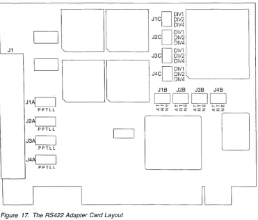
RS422 Adapter Card Layout RS422 Diagnostics
Multiport Model 2 Adapter
Overview . . . . . . . . Setting the Option Switch SW1 . . . . Wide Area Connector (WAC) Adapter
Electrical Interface Board (EIB) Cable Connections
Diagnostics . . . .
Error Messages Installing the EIB WAC Switch Settings S/390 PCI Channel Adapters
Channel Diagnostics
Invoking Channel Diagnostics
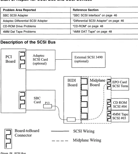
Chapter 5. SCSI BUS and Devices
Start of Repair for SCSI Bus and SCSI Devices Description of the SCSI Bus . . . . SBC SCSI Interface . . . .
Terminating the SBC SCSI Interface Attached Devices
Service Tips . . . . Differential SCSI Adapter
Terminating the AHA-2944UW Service Tips . . . .
Diagnostics . . . . CD-ROM . . . .
CDROM Drive LED Descriptions CD-ROM Drive Problems
4MM DAT Tape . . . . Using the Drive . . . .
4MM OAT Tape LED Descriptions . . . . Loading and Unloading Data Cartridges Cleaning the Drive . . . .
Chapter 6. Single Board Computer and Attached 1/0
Start of Repair for I/O and Service Processor (IOSP) Description and Layout of the Single Board Computer (SBC) 10SP Bus Structure . . . .
Configuration Jumpers CPU Speed Jumpers BIOS Operation
BIOS Errors
Running AMI BIOS Setup
)
)
:~
i,' ~_J
AMIBIOS Setup Main Menu . . . . Default P/390 Settings for SBC BIOS Setup Auto Configuration Options . . . .
Auto Configuration with Optimal Settings . . . . Auto Configuration with Fail Safe Settings . . . . Save Settings and Exit . . . . Exit without Saving . . . .
Key Conventions . .. . . . . .
BIOS Beep Codes . . . .
BIOS Error Messages
ISA BIOS NMI Handler Messages Single Board Computer Diagnostics Diskette Drive . . . . Diskette Drive LED Descriptions Diskette Drive Problems
Resolving Keyboard, Monitor, and Mouse Problems
Chapter 7. SSA RAID Adapter, SSA, and RAID SSA Maintenance Procedures (MAPs) . . . .
How to Use the MAPs . . . . . . . SSA START . . . . . . . . Service Request Numbers (SRNs)
The SRN Table . . . .
Using the SRN Table . . . . . . . . Software and Microcode Errors . . . . SSA Loop Configurations that Are Not Valid
SSA - LINK ERRORS SSA - Intermittent Link Error SSA - RAID ERRORS . . . .
SSA - Repair Verification . . . . General Information About the SSA RAID Adapter, SSA, and RAID
SSA Interfaces for Eight or Less Drives . . . . SSA Plugging Rules for Eight or Less Disk Drives
SSA Interfaces for Greater Than Eight Drives . . . . SSA Plugging Rules for Greater than Eight Disk Drives SSA Loops and Links
Loops and Data Paths Rules for SSA Loops RAID Functions Hot Spares RAID-5 Array States
Good State Exposed State Degraded State Rebuilding State Offline State SSA Link . . . .
Link Status Lights
Using the SSA Service Tools SSA Service Aids
Set Service Mode Service Aid Format Disk Service Aid Certify Disk Service Aid
58 60 62 62 62 63 63 63 64 65 68 69 70 70 70 71 73 74 74 75 77 77 77 81 81 83 88 90 · . . . . 109 · ... 110 · . . . . 111 · . . . . 111 · . . . . 112 · . . . . 112 · .. 113 · ... 113
· . . . 114
· ... 115 · .. 115 · .. 115 · .. 115 · .. 115 · ... 115 · ... 116 · . . . 116 · ... 116
· . . . 117 · . . . 118 · ... 119 · ... 119 · . . . . 119 · .. 120 · . . . . 120
The Identify Function . . . 120
1f1i
Running the SSA Service Aids . . . 121
~
Finding the Physical Location of a Device . . . . 125
Finding the Device When Service Aids Are Available . . . 125
Finding the Device When No Service Aids Are Available . . . 125
The Event/Error Logger Utility . . . 126
Analyze SSA Event Log . . . 126
Dump SSA Event Log . . . 127
Terminate SSA Event Log . . . 127
Modify Event Logger Time Out . . . 127
Using the SSA Configurator Functions . . . . . . . 128
Running the SSA Configurator . . . . . . .. . . . . 129
Chapter 8. Removal and Replacement Procedures . . . .. . . . . 141
S/390 Integrated Server FRU Types . . . . . . . . . . 142
Power Off Procedures . . . 142
If.
:jli Logic Adapter FRUs . . . 144 ~'P/390 Card Removal and Replacement . . . 144
-I
Removing the P/390 card . . . . . . . 144Replacing the P/390 Card . . . 144
RS422 Adapter Removal and Replacement . . . . 145
Removing the RS422 Adapter . . . . . . 145
Replacing the RS422 Adapter . . . . . . 145
Differential SCSI Adapter Removal and Replacement . . . 146
Removing the SCSI Adapter . . . . . . . 146
Replacing the SCSI Adapter . . . . . . . 146
dj(.
Communication Adapters Removal and Replacement . . . . . . . 147'l,;
Removing the Communication Adapters . . . . 147Replacing the Communication Adapters . . . .. 147
Channel Adapter Removal and Replacement . . . . 149
Removing the Channel Adapter . . . 149
Replacing the Channel Adapter . . . 149
SSA RAID Adapter Removal and Replacement . . . 150
Removing the SSA RAID Adapter . . . . . . . 150
Replacing the SSA RAID Adapter . . . 150
Extender Card (SSA Loop) Removal and Replacement . . . 151
Removing the Extender Card (SSA Loop) . . . .. . . . . 151
Replacing the Extender Card (SSA Loop) . . . 151
Single Board Computer Subsystem FRUs . . . . 152
SBC Card Removal and Replacement . . . . 152
Removing the SBC Card . . . . . . . . . . 152
Replacing the SBC Card . . . 152
CDROM Drive Removal and Replacement . . . . 154
Removing the CDROM Drive . . . . 154
Replacing the CDROM Drive . . . . 154
Diskette Drive Removal and Replacement . . . 154
Removing the Diskette Drive . . . . 154
Replacing the Diskette Drive . . . . 154
4MM OAT Tape Drive Removal and Replacement . . . 154
Removing the 4MM OAT Tape Drive . . . 154
Replacing the 4MM OAT Tape Drive . . . 155
Power and Mechanical FRUs . . . 156
OCA (Offline Converter Assembly) Removal and Replacement . . . . . 156
Removing the OCA . . . 156
)
Replacing the OCA . . . 156
MDAlMSA (Motor Drive Assembly I Motor Scroll Assembly) Removal and Replacement . . . 158
Removing the MDA . . . 158
Replacing the MDA . . . 158
Removing the MSA . . . 158
Replacing the MSA . . . 159
IBF (Integrated Battery Feature) Removal and Replacement . . . 160
Removing the IBF . . . 160
Replacing the IBF . . . 160
EPO (Emergency Power Off) Removal and Replacement . . . 161
Removing the EPO Card . . . 161
Replacing the EPO Card . . . 161
Adapter 1/0 Cage Assembly Removal and Replacement . . . 162
Removing the Adapter 1/0 Cage . . . 162
Replacing the Adapter 1/0 Cage . . . 162
Midplane Removal and Replacement . . . 163
Removing the Mid Plane Board . . . 163
Replacing the Mid Plane Board . . . 163
DASD Subsystem FRUs . . . 164
Disk Drive Assembly (HDA) Removal and Replacement . . . 164
Removing Array Disk Assembly (HDA) . . . . 164
Replacing the Array Disk Assembly (HDA) . . . 165
Chapter 9. Power . . . 167
1 ST Level Diagram of the Power Sub-System . . . 168
General Power Terminology . . . 168
FRU Types . . . 168
System Power Status Window . . . 169
Opening the System Power Status Window . . . 169
Menu Bar . . . 170
Display Information . . . 170
Power Failures . . . 172
Over Current Isolation . . . 190
Diagram of the OCA . . . 203
OCA Location . . . 203
OCA LED Descriptions . . . 203
OCA Switch Descriptions . . . 203
Diagram of the MDA . . . 204
General Thermal FRU Terminology . . . 204
MSAlMDA Locations . . . 204
MDAlMSA LED Descriptions . . . 204
Diagram of the IBF . . . 205
Internal Battery Feature (IBF) . . . 205
IBF Locations . . . 205
IBF LED Description . . . : . . . . 205
IBF Switch Descriptions . . . 206
. Diagram of the EPa Card . . . 207
Machine Emergency Power Off (EPO) . . . 207
Computer Room Emergency Power Off (EPO) . . . 207
EPO Card Location . . . . . . . 209
EPO LED Descriptions . . . 209
EPa Switch Description . . . 209
Power and Cooling Requirements . . . 210
Power Enclosure Power Connection . . . 210
Power and Cooling Specifications . . . 210
Customer Circuit breaker (CB) . . . 210
Line Physical Protection . . . 210
Grounding Specifications . . . 211
Specifications . . . 212
Shipping Specifications . . . 212
Service Clearance and Weight Distribution . . . 212
Environmental Specifications . . . 213
Acoustical Noise Emission Levels . . . 214
Chapter 10. Service Procedures . . . 215
Service Procedures Problem/Action List . . . 215
Collecting I/O Traces and Logs . . . 217
Summary of operation (AWSABEND.CMD) . . . 217
Snap Shot Dump . . . 217
P/390 Error Logs . . . 218
AWSERROR.LOG . . . 218
POPUPLOG.OS2 . . . 218
LANTRAN.LOG . . . 218
AWS3172.LOG . . . 219
AWS3172.ERR . . . 219
P/390 I/O Trace (AWSTRACE.LST) . . . 219
Setting up I/O Tracing by editing the CHAN.TRC File . . . 219
Modifying defaults for P/390 Trace Spooling . . . 220
Specifying Options for I/O Trace· . . . 220
Using the Device Debug Facility . . . 221
Kernel Trace . . . 221
P/390 Trace Spooling (AWSTRSP.nnn) . . . 221
Syntax . . . 221
Optional Parameters . . . 221
Sending traces and logs to IBM service (SENDLOG.CMD) . . . 222
Summary of Operation (SENDLOG.CMD) . . . 222
System 390 Integrated Server FTP Site . . . 223
Change Management Tools . . . 223
Download Fixpacks . . . 223
Unpacking Fixpacks . . . 224
Installing Fixpacks . . . 224
Setting up an Internet Connection via Modem . . . 224
Creating Diagnostic Diskettes . . . 230
Procedures . . . 230
Configuration Save/Restore Procedures . . . : . . . 231
Configuration Save/Restore Steps . . . 231
Method . . . 232
Installing S/390 Integrated Server Software . . . 232
Booting the OS/2 Utility diskettes . . . 233
Configuring the SSA RAID-5 DASD . . . 233
Rebooting OS/2 and enabling CBIOS . . . 235
Partitioning the DASD with FDISK . . . 235
Installing 10SP Software . . . 236
Booting OS/2 from SSA and formatting HPFS partitions . . . 237
Chapter 11. OS/2 Utilities . . . 239
ALC.EXE OS/2 Utility . . . 239
Syntax . . . 239
Required Parameters . . . 240
Optional Parameters . . . 240
Examples . . . 240
AWSCFG.CMD OS/2 Utility . . . 240
Syntax . . . 240
Optional Parameters . . . 240
AWSEND.CMD OS/2 Utility . . . 241
Syntax . . . 241
Optional Parameters . . . 241
AWSMOUNT.EXE OS/2 Utility . . . 241
Syntax . . . 241
Required Parameter . . . 241
Optional Parameters . . . 241
Example . . . 242
AWSPROF.EXE OS/2 Utility . . . 242
Syntax . . . 242
Required Parameters . . . 242
AWSSTART.EXE OS/2 Utility . . . 242
Syntax . . . 242
Optional Parameters . . . 242
AWSSTAT.EXE OS/2 Utility . . . 243
Syntax . . . 243
Optional Parameters . . . 243
)
Example Return Codes . . . . . . 243 243 CKDALC.EXE OS/2 Utility . . . 244Syntax . . . 244
Required Parameters . . . 244
Optional Parameters . . . 244
Example . . . 244
DEV2NAME.CMD OS/2 Utility . . . 244
Explanation of Tags . . . . . 245
Syntax . . . 245
Required Parameters . . . 246
AWSICE OS/2 Utilities . . . 246
Example . . . 246
IPL.CMD OS/2 Utility . . . 246
Syntax . . . 246
Optional Parameters . . . 246
Example . . . 247
RDEVMAP.CMD OS/2 Utility . . . 247
Syntax . . . 248
Optional Parameters . . . 248
SENDLOG.CMD OS/2 Utility . . . 248
Syntax . . . 248
Optional Parameters . . . 248
Chapter 12. Parts Catalog . . . 249
)
Assembly 1: Covers . . . 252Assembly 2: Cage Assembly . . . 254
Assembly 3: I/O Assembly . . . 256
Assembly 4: PCI Cage Assembly . . . 258
X Service Guide
Assembly 5: Power Assemblies
Chapter 13. Overview
Description
Hardware . . . . Software
Top View Locations Front View . . . .
Front View Locations Rear View
Rear View Locations Side View
Index
.260
.263 .263 .264 .264 .265 .266 .267 .268 .269 .270
)
\
)
Notices
References in this publication to IBM products, programs or services do not imply that IBM intends to make these available in all countries in which IBM operates. Any reference to an IBM product, program, or service is not intended to state or imply that only IBM's product, program, or service may be used. Any functionally equivalent product, program, or service that does not infringe any of IBM's intellectual property rights may be used instead of the IBM product, program, or service. Evaluation and verification of operation in conjunction with other products, except those expressly designated by IBM, is the user's responsibility.
IBM may have patents or pending patent applications covering subject matter in this document. The furnishing of this document does not give you any license to these patents. You can send license inquiries, in writing, to the IBM Director of Licensing, IBM Corporation, 500 Columbus Avenue, Thornwood, NY, 10594 USA.
Licenses of this program who wish to have information about it for the purpose of enabling: (i) the exchange of information between independently created programs and other programs (including this one) and (ii) the mutual use of the information which has been exchanged, should contact:
IBM Corporation Mail Station P300 522 South Road
Poughkeepsie, NY 12601-5400 USA
Attention: Information Request
Such information may be available, subject to appropriate terms and conditions, including in some cases, payment of a fee.
Electronic Emission Notices
The following statement applies to this IBM product. The statement for other IBM products intended for use with this product will appear in their accompanying manuals.
Federal Communications Commission (FCC) Statement
Note: This equipment has been tested and found to comply with the limits for a Class A digital device, pursuant to Part 15 of the FCC Rules. These limits are designed to provide reasonable protection against harmful interference when the equipment is operated in a commercial environment. This equipment generates, uses, and can radiate radio frequency energy and, if not installed and used in accordance with the instructions contained in the installation manual, may cause harmful interference to radio communications. Operation of this equipment in a residential area is likely to cause harmful interference, in which case the user will be required to correct the interference at his own expense.
) Properly shielded and grounded cables and connectors must be used in order to ,} meet FCC emission limits. IBM is not responsible for any radio or television
interference caused by using other than recommended cables and connectors, by
Trademarks
xii Service Guide
installation or use of this equipment other than as specified in the installation
I"
manual, or by any other unauthorized changes or modifications to this equipment. \ Unauthorized changes or modifications could void the user's authority to operatethe equipment.
This device complies with Part 15 of the FCC Rules. Operation is subject to the following two conditions: (1) this device may not cause harmful interference, and (2) this device must accept any interference received, including interference that may cause undesired operation.
Canadian Department of Communications Compliance Statement
This equipment does not exceed Class A limits per radio noise emissions for digital apparatus, set out in the Radio Interference Regulation of the Canadian
Department of Communications. Operation in a residential area may cause
unacceptable interference to radio and TV reception requiring the owner or operator to take whatever steps are necessary to correct the interference.
Avis de conformlte aux normes du ministere des Communications du Canada
Cet equipement ne depasse pas les limites de Classe A d'emission de bruits radioelectriques pour les appareils numeriques, telles que prescrites par Ie Reglement sur Ie brouillage radioelectrique etabli par Ie ministere des Communications du Canada. L'exploitation faite en millieu residentiel peut entrainer Ie brouillage des receptions radio et tele, ce qui obligerait Ie proprietaire ou I'operateur
a
prendre les dispositions necessaires pour en eli miner les causes.The following terms are trademarks of IBM Corporation in the United States or other countries or both.
S/370 S/390
MVS/ESA PS/2
System/390 System/370
ES/9000 VM/ESA
ESAl390 VSE/ESA
ESCON VTAM
IBM WIN-OS/2
IBMLink XGA
EtherJet Wake on LAN
• AMI and AMIBIOS are trademarks of American Megatrends, Inc.
• SCSISelect is a trademark of Adaptec, Inc.
• Pentium is a trademark of Intel Corporation in the United States and/or other countries.
)
)
l
Statement of Limited Warranty
The warranties provided by IBM in this Statement of Limited Warranty apply only to Machines you originally purchase for your use, and not for resale, from IBM or an IBM authorized reseller. The term "Machine" means an IBM machine, its features, conversions, upgrades, elements, or accessories, or any combination of them. Machines are subject to these terms only if purchased in the United States or Puerto Rico, or Canada, and located in the country of purchase. If you have any questions, contact IBM or your reseller.
Machine: System 390 Integrated Server
Warranty Period*: One Year
*Elements and accessories are warranted for three months. Contact your place of purchase for warranty service information.
Production Status
Each Machine is manufactured from new parts, or new and serviceable used parts (which perform like new parts). In some cases, the Machine may not be new and may have been previously installed. Regardless of the Machine's production status, IBM's warranty terms apply.
The IBM Warranty
IBM warrants that each Machine 1) is free from defects in materials and workmanship and 2) conforms to IBM's Official Published Specifications. IBM calculates the expiration of the warranty period from the Machine's Date of
Installation. The date on your receipt is the Date of Installation, unless IBM or your reseller informs you otherwise.
During the warranty period, IBM or your reseller will provide warranty service under the type of service designated for the Machine and will manage and install
engineering changes that apply to the Machine. IBM or your reseller will specify the type of service.
For a feature, conversion, or upgrade, IBM or your reseller may require that the Machine on which it is installed be 1) the designated, serial-numbered Machine and 2) at an engineering-change level compatible with the feature, conversion, or upgrade. Some of these transactions (called "Net-Priced" transactions) may include additional parts and associated replacement parts that are provided on an
exchange basis. All removed parts become the property of IBM and must be returned to IBM.
Replacement parts assume the remaining warranty of the parts they replace.
If a Machine does not function as warranted during the warranty period, IBM or your reseller will repair or replace it (with a Machine that is at least functionally equivalent) without charge. If IBM or your reseller is unable to do so, you may return it to your place of purchase and your money will be refunded.
xiv
Service GuideIf you transfer a Machine to another user, warranty service is available to that user for the remainder of the warranty period. You should give your proof of purchase and this Statement to that user.
Warranty Service
To obtain warranty service for the Machine, you should contact your reseller or call IBM. In the United States, call IBM at 1-800-IBM-SERV (426-7378). In Canada, call IBM at 1-800-465-6666. You may be required to present proof of purchase.
Depending on the Machine, the service may be 1) a "Repair" service at your location (called "On-site") or at one of IBM's or a reseller's service locations (called "Carry-in") or 2) an "Exchange" service, either On-site or Carry-in.
When a type of service involves the exchange of a Machine or part, the item IBM or your reseller replaces becomes its property and the replacement becomes yours. The replacement may not be new, but will be in good working order and at least
functionally equivalent to the item replaced. (
It is your responsibility to:
1. obtain authorization from the owner (for example, your lessor) to have IBM or your reseller service a Machine that you do not own;
2. where applicable, before service is provided
-a. follow the problem determination, problem analysis, and service request procedures that IBM or your reseller provide, .
b. secure all programs, data, and funds contained in a Machine, c. inform IBM or your reseller of changes in a Machine's location, and d. for a Machine with exchange service, remove all features, parts, options,
alterations, and attachments not under warranty service. Also, the Machine must be free of any legal obligations or restrictions that prevent its
exchange; and
3. be responsible for loss of, or damage to, a Machine in transit when you are responsible for the transportation charges.
Extent of Warranty
IBM does not warrant uninterrupted or error-free operation of a Machine.
Misuse, accident, modification, unsuitable physical or operating environment, improper maintenance by you, or failure caused by a product for which IBM is not responsible may void the warranties.
THESE WARRANTIES REPLACE ALL OTHER WARRANTIES, EXPRESS OR IMPLIED, INCLUDING, BUT NOT LIMITED TO, THE IMPLIED WARRANTIES OF MERCHANTABILITY AND FITNESS FOR A PARTICULAR PURPOSE.
HOWEVER, SOME LAWS DO NOT ALLOW THE EXCLUSION OF IMPLIED WARRANTIES. IF THESE LAWS APPLY, THEN ALL EXPRESS AND IMPLIED WARRANTIES ARE LIMITED IN DURATION TO THE WARRANTY PERIOD. NO WARRANTIES APPLY AFTER THAT PERIOD.
In Canada, warranties include both warranties and conditions.
)
)
j
Limitation of Liability
Circumstances may arise where, because of a default on IBM's part (including fundamental breach) or other liability (including negligence and misrepresentation), you are entitled to recover damages from IBM. In each such instance, regardless of the basis on which you are entitled to claim damages, IBM is liable only for:
1. bodily injury (including death), and damage to real property and tangible personal property; and
2. the amount of any other actual loss or damage, up to the greater of $100,000 or the charge for the Machine that is the subject of the claim.
Under no circumstances is IBM liable for any of the following:
1. third-party claims against you for losses or damages (other than those under the first item listed above);
2. loss of, or damage to, your records or data; or
3. economic consequential damages (including lost profits or savings) or incidental damages, even if IBM is informed of their possibility.
Some jurisdictions do not allow the exclusion or limitation of incidental or
consequential damages, so the above limitation or exclusion may not apply to you.
This warranty gives you specific legal rights and you may also have other rights which vary from jurisdiction to jurisdiction.
)
)
Safety
Safety Notices
Safety notices are printed throughout this service guide. DANGER notices warn you of conditions or procedures that can result in death or severe personal injury. CAUTION notices warn you of conditions or procedures that can cause personal injury that is neither lethal nor extremely hazardous. Attention notices warn you of conditions or procedures that can cause damage to machines, equipment, or programs.
The following DANGER notice appears on pages 167 and 172.
DANGER
Service of any subassemblies under power outside of their machine frame mounts is strictly prohibited.
Laser Safety Information
CAUTION:The coupling facility, ESCON, FICON, and OSA channel laser ports are designed and certified for use only with optical fiber and connectors having characteristics specified by IBM. The use of any other connectors or fiber may result in emission of laser power levels capable of producing injury to the eye if directly viewed. Use of non-specified connectors or fiber could violate the class 1 certification.
CAUTION:
Data processing environments can contain equipment transmitting on system links with laser modules operating at greater than class 1 power levels. For this reason, it is advised never to look into the end of an optical fiber cable or open receptable. The inspection or repair of optical fiber cable assemblies and receptacles should be performed by trained service personnel only.
Laser Compliance
© Copyright IBM Corp. 1999
The laser modules are certified in the U.S. to conform to the requirements of DHH8 21 CFR Subchapter J for Class 1 laser products. Elsewhere, they are certified to be in compliance with IEC 825 (first edition 1984) and CENELEC HD 482 81 as a Class 1 laser product. The coulping facility channel modules have also been tested and approved to comply with international Class 1 laser product certifications. Consult the label on each part for laser certification numbers and approval information.
Class 1 laser products are not considered to be hazardous. Internally, the laser moc'jles operating on multimode fiber contain a Class 3b laser that is nominally a 5.0 milliwatt source operating in the wavelength region of 780-850 nm. Internally, the laser modules operating on single-mode fiber contain a class 3b laser that is nominally a 5.0 milliwatt source operating in the wavelength region of 1270-1340
nanometers. All laser modules are designed so that there is never any human
!. :
access to laser radiation above a Class 1 level during normal operation, usermaintenance, or prescribed service conditions.
CAUTION:
Although the IBM module is safe, there may be other Laser modules in the system link that may not be safe under all conditions. For this reason it is advised to never view the end of the optical fiber cable or open receptacle. However, some repair activities of optical fiber cable assemblies may require the use of special viewing devices. In such cases, disconnecting both ends of the fiber is mandatory. As an additional precaution, viewing equipment with the proper Laser viewing protection filters must be used.
The OSA fiber optic modules are certified in the U.S. to conform to the requirements of DHHS 21 CFR subchapter J for Class 1 laser products.
Elsewhere, they are certified to be in compliance with IEC 825 (first edition 1994) and CENELEC HD 482 S1 as a Class 1 laser product. These modules have been tested and approved to comply with International Class 1 laser product
certifications. Consult the label on each transceiver for laser certification numbers and approval information.
Observe the following caution notice when handling ESCON, coupling facility, or OSA2 fiber optic channel cables.
CAUTION:
Data processing environments may contain equipment transmitting on system links, with Laser modules operating at greater than Class 1 power levels. For this reason, it is advised never to look into the end of an optical fiber cable or open receptacle. The inspection and/or repair of optical fiber cable assemblies and receptacles should be performed by trained service personnel only.
(
I
World Trade Safety Information
xviii
Service GuideSeveral countries require the safety information contained in product publications to be presented in their national languages. If this requirement applies to your
country, a safety information booklet is included in the publications package ( shipped with the product. The booklet contains the safety information in your 'Z national language with references to the US English source publications. Before
Preface
Who Should Use This Guide
This guide is for service representatives who perform problem isolation and repair actions on the System 390 Integrated Server. The service representative should have a good understanding of the OS/2 operating system.
How This Book Is Organized
© Copyright IBM Corp. 1999
This book contains the following chapters:
• Start
This is a list of problem symptoms and the chapter or section to reference to resolve the problem.
• System Bring-Up Sequence
Contains a flowchart of the sequence of events during power up, and details steps to follow if an abnormal condition occurs.
• Processor Unit
This includes a list of diagnostic procedures and a list of error codes and messages that can result from running the diagnostics.
• PCI/ISA BUS
Describes the PCI/ISA Local Bus, and has descriptions of each PCI interfci.l~e adapter.
• 10SP
Describes the 10SP, the data flow, diagrams, and a description of the BIOS operation.
• SSA Dasd
Contains service information for the SSA adapter and attached storage devices.
• Power
Includes a layout and description of the MSA, MDA, OCA, and IBF. A power map is included as a starting point for analyzing a system power failure.
• Service Procedures
Explains the use of P/390 I/O Traces, P/390 Snap Shot Dumps, FixPack and Patch application.
• OS/2 Utilities
Describes all the OS/2 Utilities applicable to the System 390 Integrated Server.
• Parts Catalog Lists each part and order number for the System 390 Integrated Server.
• Overview
Gives a 3D detailed picture of the System 390 Integrated Server and describes each element.
XX Service Guide
r
f
I
I
(
(
)
Chapter 1. START
This is the starting point for all service calls.
Problem
I
Service Activity Start List
Problem
Customer reports a failing Symptom (Le. System Hang, wait), or the Display is blank and system beeps,
or the Display is blank,
or the Display is blank with no power indication, or the machine fails to boot up correctly, or the problem is unknown
OS/2 Trap Errors 0000-0010
Reports of an error message (see the appropriate chapter)
• AWSxxxxxxx - P/390
• Communication Error Message - PCI/ISA • BIOS error messages - Single Board Computer • System Power Status - Power
• SRNxxxxx - SSA RAID
or need Procedures for running diagnostics
Customer reports a failure on the Disk Subsystem
Customer reports a failure on a communication Adapter or network
Customer reports a power problem
Customer reported problem with Single Board Computer (Le. mouse, keyboard, monitor, floppy disk, CDROM, 4MM DAT Tape)
For information on Licensed internal code changes Installing traps (fixes) for Licensed internal code changes Backup the customer configuration information (critical data) Log and Trace Information and Procedures
For information on FRU Removal and Replacement Procedures
© Copyright IBM Corp. 1999
Start
Instructions
Go to Chapter 2, "Solving Problems" on page 3
Go To Application Software error and contact the next level of support.
Select the appropriate section:
• Go to Chapter 3, "P /390 Processor Card" on page 7 • Go to Chapter 4, "PCI/ISA
BUS and Adapters" on page 13
• Go to Chapter 6, "Single Board Computer and Attached I/O" on page 51
• Go to Chapter 9, "Power" on page 167
• Go to Chapter 7, "SSA RAID Adapter, SSA, and RAID" on page 73
Go to Chapter 7, "SSA RAID Adapter, SSA, and RAID" on page 73
Go to Chapter 4, "PCI/ISA BUS and Adapters" on page 13
Go to Chapter 9, "Power" on page 167
Go to Chapter 6, "Single Board Computer and Attached I/O" on page 51
Go to Chapter 10, "Service Procedures" on page 215
Go to Chapter 8, "Removal and Replacement Procedures" on page 141
Start
(
\Solving Problems
Chapter 2. Solving Problems
The S/390 Integrated Server uses many of the 10SP adapters and devices. These faults can be diagnosed using the standard S/390 Integrated Server maintenance package.
1. Verify the correct operation of the S/390 Integrated Server using the appropriate procedures. This includes:
• Visual checks
• Examine Error Logs
• Running Diagnostics.
2. If the customer nas a reported problem with a specific component, run its diagnostics first.
3. If no problems are found, run the P/390 diagnostics. Refer to "Diagnostics" on page 8 for the procedures.
4. If the P/390 diagnostics do not detect a problem, view the P/390 error log. Refer to "P/390 Error Logs" on page 218 for the procedures.
The 10SP can detect FRU errors and notify the customer that the machine requires service. The identification of failing power FRUs will be by service lights, as well as the Power Monitoring application. Isolation of PCI devices will be by error messages and FRU replacement. All Service will be via hardcopy procedures.
OS/2
Problems
The S/390 Integrated Server I/O subsystem is based on a customized OS/2. If any programs are added to OS/2 that are not part of the Integrated Server product, these applications can affect both the performance and reliability of your S/390 I/O.
If you have added new applications and then experience any problems, first stop running the applications while the P/390 is IPLed, to see if the problems cease. If the problems persist, then try uninstalling the applications. If you still have problems, then contact your IBM Business Partner; your C: drive may have '\ to be formatted and reloaded.
}
'I'
Sequence of events from a power up
The following MAP is the sequence of events with visual indicator of what happens in each step and if abnormal condition a 'Go to' within the Service Guide that would aid in the problem solving process.
Power up sequence is:
• Power On, and Hardware Resets • Phase 1 POST tests.
• Phase 2 POST tests.
• Adapter BIOS Loads (bottom to top)
• Search for bootable device, floppy then CD-ROM then SSA Disk.
Should find OS/2 on SSA Disk.
• Load OS/2 device drives from config.sys.
Solving Problems
1
Power on the ~onitor.
Does the Monitor power on correctly?
YES NO
l
Go to "Resolving Keyboard, Monitor, and Mouse Problems" on page 712
Verify that the power cables are properly connected.
Power on the system.
Are either of the DCA "PWR OUT" indicators on ?
YES NO
l
Go to "Power Failures" on page 1723
Are there SEEP codes during Power-on-self Test?
NO YES
~ Go to "BIOS Beep Codes" on page 64
4
Was BIOS logo displayed?
YES NO
~ Go to "PC I Bus Isolation" on page 18
5
Are there Error Messages during Power-on-self Test?
NO YES
Go to "BIOS Error Messages" on page 65
4
Service GuideLight will be Amber at first.
Light will change to Green when the SSC starts running the Power On Self Test (POST).
This step takes approximately 20 seconds.
Check the power indicators for both OCAs.
When you turn on the server, it performs a series of tests to check the operation of the S/390 Integrated Server components and features. This series is called the power-on-self test or POST.
Phase 1 POST generates beep codes to indicate fatal error that will not allow the system to continue the bootup process.
Phase 2 of the POST tests will display the BIOS logo.
American Megtrends AMIBIOS (C)
TRENTON Technology Inc.
Failure to see the logo usually indicates a hung PCI bus.
If POST detects a problem, an error message appears on your screen. A single problem can cause several error messages to appear. When this occurs, work to correct the cause of the first error message.
If memory tests complete, POST test completed successfully.
,
6
Do any PCI adapters initialize?
YES NO
~ Go to "PCI Bus Isolation" on page 18
7
Has the SBC SCSI BIOS Initialization completed (used to access the CD-ROM and 4mm Tape drive), and device list displayed correctly?
YES NO
8
Go to "Start of Repair for SCSI Bus and SCSI Devices" on page 45
Has the SSA Adapter BIOS Initialization completed?
YES NO
9
~ Go to Chapter 7, "SSA RAID Adapter, SSA, and RAID" on page 73
Does OS/2 boot up complete and the OS/2 Desktop appear?
NO YES
~ Check Chapter 1, "START" on page 1 for another possible entry point, or call next level support for help.
10
Do the SCSI or SCSI3480 device drivers fail to load or produce error messages?
NO YES
~ Go to "Start of Repair for SCSI Bus and SCSI Devices" on page 45
Solving Problems
If no PCI adapters initialize this indicates a problem on the PCI bus.
When the SBC SCSI device driver starts to load the following is displayed, and the adapter is
tested. .
Adaptec AIC-7880 Ultra/Ultra W BIOS
(c) 1996
Adaptec~Inc. All Rights Reserved.
«< Press <CTRL><A> for SCSISelect(TM) Utility!
»A device list will be displayed.
SCSI ID:LUN NUMBER
#:#3:0 - ARCHIVE Python
SCSI ID:LUN NUMBER
#:#4:0 - IBM
CDRM00203
The BIOS not installed message indicates the device driver has completed loading.
When the SSA device driver starts to load the following is displayed:
IBM SSA CBIOS (C) v1.07 -- currently enabled
Press TAB key to disable the CBIOS
When the SSA driver completes loading the following is displayed:
IBM SSA CBIOS Extension (C) v1.07 6350
Note: Do not disable the CBIOS option.
f,
Solving Problems
11
Do the ARTIC960 device drivers fail to load or produce error messages?
NO YES
l
Go to "Channel Diagnostics" on page 4312
Check Chapter 1 , "START" on page 1 for another possible entry point, or call next level support for help.
6
Service GuideThe ARTIC960 adapters are the S/390 Parallel or Serial Channel Cards.
Note: There may be more than one channel card installed in the system. The RIC010 message should identify the failing channel card number
..
I
I
I
Description of the Processor Unit
Chapter 3.
P/390
Processor Card
Processor Unit Problem/Action List
Problem Area Reported Reference Section
P/390 Install "Installing P/390 Hardware and Software" on
page 8
Error message received "P/390 Error Messages" on page 11
Maintenance "Diagnostics" on page 8
Chapter 1 0, "Service Procedures" on page 215 see "P/390 Error Logs" on page 218
The SAD display says "STOPPED" or "DOWN" "STOPPED and DOWN Displayed on the System/390 TM Activity Display" on page 10
Removal/Replacement Procedures "P/390 Card Removal and Replacement" on page 144 for the removal and replacement of the P390 card
Description
The S/390 Integrated Server consists of a P/390 processor card with 256MB of integrated S/390 memory. The P/390 is supported in the S/390 Integrated Server Model 801.
The P/390 runs standard S/390 operating systems, such as VM/ESA, VSE/ESA, MVS/ESA, and OS/390. The P/390 microcode is loaded automatically during the start up of OS/2. Because the S/390 operating system is not usually loaded and started automatically, it may require a manual IPL.
The P/390 processor card is located in a PCI adapter slot. The card is an individual FRU and can be replaced separately. No cables are used, and no jumpers or adjustments are required during a replacement.
P/390 diagnostics are provided as part of the P/390 Licensed Internal Code. These diagnostics reside on the P/390E Advanced Diagnostics and LlC diskette. The diagnostics provide a complete checkout of the P/390 card and can isolate most faults to a single FRU. The P/390 diagnostics are invoked by booting the diskette. The results are displayed on the screen.
The P/390 running one of the S/390 operating systems utilizes standard PC adapters and devices as I/O for the P/390. In most cases, hardware failures are indicated by the standard OS/2 device drivers and are logged in various OS/2 error logs (IE: LANTRAN.LOG, POPUPLOG.OS2). The standard S/390 Integrated Server diagnostics and maintenance package is used for hardware fault isolation and repair. In addition, any faults detected by the P/390 device managers are shown in a special P/390 pop-up window and are logged in a P/390 unique error log. (AWSERROR.LOG)
S/390 operating systems include problem determination tools such as dumps, traces message displays, logs, and so on. In addition, the P/390 I/O code running under OS/2 provides channel, device manager and manops traces. Selected device managers also support a snap-dump capability. All of these tools can be used by support personnel to resolve P/390 processor and I/O subsystem software problems.
• I
I
Installing
P/390
Hardware and Software
See "Power and Cooling Requirements" on page 210 for power and cooling requirements.
See "Specifications" on page 212 for physical and environmental specifications.
See Chapter 8, "Removal and Replacement Procedures" on page 141 for installing each piece of hardware.
Plug in all the SSA disk drives that you are going to use. Adding more drives later is possible, but you will have to configure an additional array each time, which reduces the usable disk space due to the RAID-5 parity drive (Le. n m MB drives yields (n-1)m MB of usable space.
Cable all the drives (from 3 to 16 drives) into ONE SSA loop. Use the A ports of the SSA adapter card only.
If you have eight or fewer drives, plug them into the first two columns, under the Left Extender Card, and use two SSA cables:
• See Figure 33 on page 111
If you have nine to sixteen drives, plug them into the first two columns, under the Left Extender card; then into the third and fourth columns, under the Middle Extender card, and use three SSA cables:
• See Figure 34 on page 112
Remember that if you do not have exactly eight or sixteen drives then SSA Dummy Drive Modules must be plugged into the unused slots in any column pair that is partially filled. This is because the SSA cabling MUST complete a loop from adapter port A1 back to port A2 without breaks.
See "Installing S/390 Integrated Server Software" on page 232 for installing the S/390 Server software.
Diagnostics
The testing of the P/390 card begins at the PCI channel connector and penetrates progressively into the processor and memory. A specific functional area is tested before it is used to test a subsequent area. The diagnostic proceeds in five phases until an error is detected or the P/390 has passed all the tests.
1. Phase 1 examines the environment.
• Checks for the presence of the P/390. • Initializes the P/390 to a known state.
2. Phase 2 tests the interface between the PCI and the P/390 before loading any P/390 microcode.
• PCI Channel interface • Control store tests
• Program control and status register tests
3. Phase 3 loads microcode and starts initial interactive testing.
• Timer tests • COMBUF tests • Storage nucleus • Interrupts • Alerts
4. Phase 4 completes the testing of the processor and static storage testing.
5. Phase 5 completes the testing of the key array and interactive storage test!ng.
Procedure
To run diagnostics for the P/390, do the following:
1. With the customer's help, stop all 8/390 programs and shut down the S/390 operating system if it is actively running on the P/390.
2. Using the S/390 Integrated Server CD-ROM you must create a diagnostic diskette. Using the procedure described in "Creating Diagnostic Diskettes" on page 230 make a diskette for the P/390 Diagnostics.
3. Shut down OS/2.
4. Insert the diskette in the diskette drive.
5. Press CTRL-ALT-DEL or press the RESET switch.
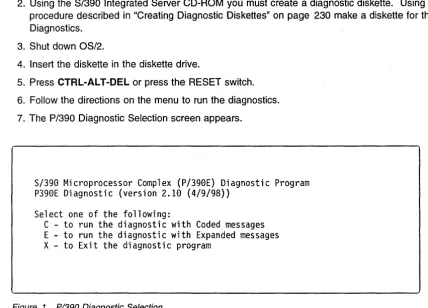
6. Follow the directions on the menu to run the diagnostics.
7. The P/390 Diagnostic Selection screen appears.
S/390 Microprocessor Complex (P/390E) Diagnostic Program
P390E Diagnostic (version 2.10 (4/9/98»
Select one of the following:
[image:30.617.55.484.176.484.2]C - to run the diagnostic with Coded messages
E - to run the diagnostic with Expanded messages
X - to Exit the diagnostic program
Figure 1. PI390 Diagnostic Selection
8. To start the diagnostics, type C or E.
• C runs with reduced test information messages.
• E runs the same tests as C but provides an expanded set of test information messages. These messages are primarily used by support personnel.
• X exits this screen without starting the diagnostics.
-=-=-=-=-=-=-=-=-=-=-=-=-=-=-=-=-=-=-=-=--=-=-=-=-=-=-=-=-=--=-DIAGNOSTIC RESULT:
P390E Adapter SUCCESSFULLY PASSED all tests.
-=-=-=-=-=-=-=-=-=-=-=-=-=-=-=-=-=-=-=-=--=-=-=-=-=-=-=-=-=--=-Environment information
The P390E adapter has 256 MB of ECC memory on the processor card.
Diagnostic program version 2.10 (4/9/98)
Diagnostic took 110 second(s)
Press Enter to return
Figure 2. PI390 Diagnostic Screen
9. The diagnostic completes with a screen similar to Figure 2. If the tests were successful, the P/390 is ready to IPL the S/390 operating system. If the test found a problem, the diagnostic indicates a repair action.
If you receive any messages about hardware failures, replace the P/390 adapter. See "P/390 Card Removal and Replacement" on page 144.
1 O. When testing is complete, remove the diagnostic diskette and the CD disc and reboot the system by pressing CTRL-AL T-DEL (or by press the RESET switch).
STOPPED and DOWN Displayed on the System/3g0
™Activity Display
Your P/390 may appear to be malfunctioning while the P/390 System/390 Activity display displays STOPPED or DOWN.
STOPPED signals that the P/390 Processor is in the stopped state. The execution of S/390 instructions has been interrupted. This state occurs when:
• You click on STOP from the P/390 MANUAL OPERATIONS session.
• or if the ADDR COMPARE function in the P/390 MANUAL OPERATIONS session has stopped the processor because of a S/390 address compare match.
• or because the C:\P390\CHAN.TRC contains an I/O address with a "S" or "I" suffix. This causes the processor to stop every time I/O is done to that address.
To start the P/390 again, click on START from the P/390 MANUAL OPERATIONS session.
The STOPPED state can also occur while S/390 operating systems is IPUng, and after the S/390 operating system has been shut down. If the S/390 operating system was shut down, clicking START from the P/390 MANUAL OPERATIONS session will
not
start up the P/390 Processor again. You must IPL the P/390 by either clicking IPL from the P/390 Manual Operations Session or by double-clicking on the IPL P/390 icon.The DOWN indicator signals that an error has occurred in the P/390 Processor or its I/O subsystem. The P/390 Processor is no longer operational.
)
P/390 Error Messages
Check the System Operator session and the P/390 MANUAL OPERATIONS session for any messages that may indicate the reason for the failure of the P/390. Refer to online message file by typing VIEW C:\P390\P390MSG.lNF to determine how to proceed.
If there are no messages indicating the reason for the failure, run P/390 diagnostics.
P/390
Error Messages
This chapter explains the meaning of the various messages you can receive while using the components of your P/390.
• The S/390 Operating Systems, VM/ESA, MVS/ESA, VSE/ESA, and OS/390 generate many types of messages. These are the same messages and error codes that occur when running on a S/390 mainframe system. When you receive these messages in a P/390 VSE/ESA or VM/ESA session, refer to either the VSEIESA Messages and Codes manual or the VMIESA System Messages and
Codes manual. For MVS/ESA messages, refer to the Library Guide for the version of MVS/ESA you are running. For OS/390 messages, see the OSI390 Information Roadmap.
Your P/390 generates two kinds of messages:
• Configurator messages, which you see only when you are running the P/390 Configurator
• P/390 messages, which can be identified by the letters AWS at the beginning of each message identifier. All AWS messages are described in this chapter. Note that some messages are related to a particular S/390 operating system and may not apply to your system.
A WS Message Format
Messages generated by the S/390 Integrated Server are written in the following format:
AWSzzznnnx text . . . .
Where:
zzz is a 3-character identifier. See Figure 3 on page 12 for an explanation of these identifiers.
nnn is a 3-digit message identifier number is one of the following:
x
I for informational messages W for warning messages E for error messages S for severe error messages
T for terminating or ABEND messages
S/390 Integrated Server messages appear in one of two places:
• In a pop-up window that overlays the main display area of anyone of your sessions. The messages appearing here are generated by the session managers and do not directly result in an ABEND in the system. Usually, you press ENTER to continue processing.
• As a CP or CMS message in a S/390 Integrated Server VM or host VM session.
If you missed a message when it appeared on the screen, the message is logged in an OS/2 file residing in the current C:\P390 subdirectory called AWSERROR.LOG. The file is not overwritten at each IPL of the
I /'1
P/390
Error Messages
system. You can save the file from the previous session for review by renaming it before you IPL the system again.
To view this file, select the OS/2 session and do one of the following:
• Use the TEDIT command.
• Print the file on your S/390 Integrated Server-attached printer, if available.
Help is available for each message. It provides the same information that appears in this document.
zzz
Program Name FunctionABN AWSABEND.CMD Abnormal Termination handler. CHN AWSCHAN.EXE P/390 channel emulator
CKD AWSCKD.EXE Count Key Data (CKD) DASD emulator CMD OS2 EXEC Execute OS/2 commands from CMS CML AWS3274.EXE 3270 emulation over LAN
DDX AWS370DD.SYS P/390 device driver
DEV AWSDEV.EXE Interface tor device driver emulation of S/390 devices OFT AWS3274.EXE 3274 Control Unit emulation
DIE AWSINTF.EXE Disabled wait-state for S/390 DIW AWSINTF.EXE Disabled wait-state codes for S/370 DMI AWSDM.DLL Device manager interface
DSK AWSFBA.EXE Fixed-block (FBA) DASD emulator
ICA AWSICA.EXE SDLC/BSC Integrated Communication Adapter (ICA) support ICE AWSICE.EXE S/390 Parallel or Escon Channel Adapter
KRN AWSMAIN.EXE P/390 I/O subsystem
LCS LCS3172.EXE 3172 LAN Channel Station for TCP/IP
../
MNT AWSMOUNT.EXE Associates an OS/2 file with an emulated tape drive OMA AWSOMA.EXE Optical Media Attach
PCS AWSPCSRV.EXE Provides communication path between P/390 and OS/2 PCY PCOPY EXEC CMS command to copy files between CMS and OS/2 PRT AWS2821.EXE AWS2821 line printer emulation (1403)
POS AWSPOSDD.SYS POSPOWER device driver RPU AWS2540.EXE 2540 card reader emulation TAP AWSTAPE.EXE 3803/3420 tape emulation TCP AWS3274.EXE 3270 TELNET sessions TOO AWSMAIN.EXE Time-ot-day prompt TRC AWSTRCSP.EXE Trace spooling support
XCA LAN3172.EXE 3172 LAN Gateway (SNA) emulation
Figure 3. AWS Message Format
PCI/ISA BUS Isolation
Chapter 4. PCI/ISA BUS and Adapters
Start of Repair for PCI·ISA Bus and Adapters
Problem Area Reported Reference Section
PCI Bus Isolation "PCI Bus Isolation" on page 18
Token Ring Information and Diagnostics "Token-Ring Adapter" on page 19
Ethernet Information and Diagnostics "EtherJet PCI Adapter" on page 30
RS422 Information and Diagnostics "RS422 Adapter" on page 33
MultiPort 2 Information and Diagnostics "Multiport Model 2 Adapter" on page 36
Wide Area Connector Information and "Wide Area Connector (WAC) Adapter" on
Diagnostics page 38
Channel Adapters Information and Diagnostics "S/390 PCI Channel Adapters" on page 43
SCSI Adapter Information and Diagnostics "Start of Repair for SCSI Bus and SCSI Devices" on page 45
Adapters and Cage Assembly Removal and Chapter 8, "Removal and Replacement
Replacement Procedures Procedures" on page 141
Description of the PCI/ISA BUS
The Peripheral Component Interconnect (PCI) Local Bus is a 32-bit bus with multiplexed address and data lines. It is intended for use as an interconnect mechanism between integrated peripheral controller components, peripheral add-in boards and processor/memory systems.
Maximum Configurations
\ A total of four Parallel Channel Adapter (PCA) or two ESCON Channel Adapter (ECA) in any combination.
/
Up to three WAC Adapter (WAC) cards if no Multiport Model 2 Adapter (MPM2) cards are present. This gives a total of 6 SDLC or Bisync lines.
Up to two Multiport Model 2 Adapter (MPM2) cards if no more than one WAC Adapter (WAC) card is present. Each Multiport Model 2 Adapter (MPM2) supports 8 SDLC lines (dial-in or leased line, no dial-out)for a total of 16 lines.
A total of 4 LAN cards of either Token Ring (TR) or Ethernet (ETH). The first Ethernet is built into the 1/0
and Service Processor so there will never be more than three Ethernet cards present.
- I
PCIIISA BUS Isolation
Adapter Plugging Rules for PCIIISA slots
The slots are numbered 1 through 21 (LG 01 to LG 21) with 1 being the top most slot and 21 the closest to the floor.
Figure 4. Adapter and Slot Number
Slot Adapter Purpose ReqlOpt Order 1 2944UW SCSI Adapter 3490-F01 Tape Optional
2 RS422 Power Control Required 3 SSA Adapter OASO Controller Required 4 Reserved
5 PCA or ECA S/390 Channel (ARTIC960) Optional 4th PCA or ECA (note 3) 6 PCA or ECA S/390 Channel (ARTIC960) Optional 3rd PCA or ECA (note 3) 7 PCA or ECA S/390 Channel (ARTIC960) Optional 2nd PCA or ECA (note 3) 8 PCA or ECA S/390 Channel (ARTIC960) Optional 1 st PCA or ECA (note 3) 9 Reserved
10 Reserved 11 Reserved
12 P/390 256Meg Processor Required
13 TR LAN Optional 4th TR
14 TR or ETH LAN Optional 3rd TR or 4th ETH 15 TR or ETH LAN Optional 2nd TR or 3rd ETH 16 TR or ETH LAN Optional 1 st TR or 2nd ETH 17 Serial 1, Parallel 1, USB, Seriabr2;lE8:]teaker Required
18 SBC I/O and Service Processor Required Video Connection
1st ETH
Keyboard Connection Mouse Connection
19 WAC SOLC/Bisync Optional 1st WAC (note 1)
20 WAC or MPM2 SOLC/Bisync Optional 2nd WAC or 2nd MPM2 (note 1,2) 21 WAC or MPM2 SOLC/Bisync Optional 3rd WAC or 1st MPM2 (note 1,2) Note:
1. Each Wide Area Connector (WAC) card has two ports. Each port can be either RS-232, V.35, or X.21. All WAC cards in the system must be either ICA (AWSICA for VMHI or VSEHI) or XCA (WAN3172 for VM, VSE, or OS/390™). ICA can be SOLC or Bisync, while XCA is only SOLC. The WAC is an ISA bus adapter and has switches on the card that must be set.
2. Each MPM2 card supports up to 8 SOLC lines. MPM2 is XCA only. MPM2 is an ISA bus adapter that has switches on the card that must be set.
3. A total of four Parallel Channel Adapter (PCA) or two ESCON HI Channel Adapter (ECA) in any combination. The card installed in the highest slot number (first slot from the bottom) will be channel card
o.
)
)
PCI/ISA Slots
1 I
21
31
41
51
61
71
81
91
101
11
12
13
14
151
161
17
Serial/Parallel/USB Ports
SBC SLOT
181
II• +3,3V
PCI • +12
to • -12
PCI Bridge
.-5
PCI to PCI Bridge
PCISLOTS
PCI to PCI Bridge
PCI to PCI Bridge
• +5
191
I}
20 ...
1 _ _ _ _ _ _ _
---'1
ISASLOTS
211
1
Figure 5. Location layout of the board and slots
Note: minus 5 volts isn't provided. Its LED will remain off.
PCI/ISA BUS Isolation
PCIIISA BUS Isolation
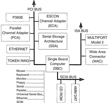
SBC/PCIIISA Bus Structure - Logical View
•
PCIBUS
I
P390E
L
ESCON
Parallel
_.I
~
Channel Adapter
(ECA)
Channel Adapter
-(PCA)
i ETHERNET
~
iTOKEN
RING~
Serial Storage
Arch itectu re
(SSA)
Single Board
a..-_~
Computer
MouSe-_ _ _ TL _ _
(S---,B..--C_)_~
•
ISA BUS
MULTIPORT
1
-Model 2
Wide Area
1 -
Connector
(WAC)
Keyboard---~ Monitor---I Floppy - - - I
Serial - - - I
SCSI BUS
~Parallel _ _ _ ---I
Universal Serial Bus_ Ethernet
[image:37.617.101.465.101.449.2]SCSI _ _ _ _ --I
Figure 6. Logical Bus Structure Diagram
16 Service Guide
~ ~'
o
o
JJ
o
PCIIISA BUS Isolation
SBC/PCI/ISA Bus Structure - Physical View
SSC
(slot 18)
Keyboard (IRQ 1)
ISA BUS
Serial1
(IRQ 4)
Serial2
(IRQ 3)
Floppy
(IRQ 6)
Parallel
(IRQ 7)
Ethernet (IRQ 10)
SCSI
(IRQ 11)
Mouse
(IRQ 12)
I
PCI
to
PCI
PCI
to
PCI
Bridge
Bridge
I
I
[image:38.623.42.512.64.705.2]PCI slots
PCI slots
13 (IRQ 11)
9 (IRQ 11)
14 (IRQ 15)
10 (IRQ 15)
15 (IRQ 9)
11 (IRQ 9)
16 (IRQ 10)
12 (IRQ 10)
Figure 7. PhYSical Bus Structure Diagram
ISASlots
19,20,21
(IRQs 3 and 5)
Memory D4000-DFFF
Primary
4-I~
PCI BUS
PCI
to
PCI
Bridge
Secondary
1 - - - , •I
I
PCI slots
5 (IRQ 11)
6 (IRQ 15)
7 (IRQ 9)
8 (IRQ 10)
PCI BUS
PCI to PCI
Bridge
Tertiary
4. "-PCI BUS
PCI slots
1 (IRQ 11)
2 (IRQ 15)
3 (IRQ 9)
4 (IRQ 10)
PCIIISA BUS Isolation
Solving Adapter Problems
If the customer reports a problem with a specific adapter:
1. Use the error message to isolate failure
2. Run diagnostics
3. If no problems are found run the application to recreate the failure
4. If you cannot recreate or resolye the problem contact the next level of support
PCI Bus Isolation
During bring up if the lights on the monitor remain Amber and there have not been any beep codes signaled by the SBC card, you may have a bad PCI or ISA adapter that is affecting the operation of the I/O and Service Processor. To isolate the problem:
1. Power down the system.
2. Remove all adapters from the PCI and ISA slots.
3. Leave the SBC card seated.
4. Disconnect the SCSI cable and Diskette cable from the Single Board Computer
5. Power up the system.
6. Refer to "Sequence of events from a power up" on page 3 to verify the power sequence.
7. If the initial power on screen now displays:
American Megtrends AMIBIOS (C)
TRENTON Technology Inc.
Then one of the adapters is bad.
8. Power down the system.
9. Plug the cables and adapters in the following sequence one at a time, poweri