E X P R E S S
Open Access
The Nanostructuring of Atomically Flat
Ru(0001) upon Oxidation and Reduction
A. Goriachko
1*and H. Over
2Abstract
The O/Ru(0001) system is widely studied due to its rich phase variety of various stoichiometry and atomic arrangements, including the formation of a RuO2/Ru(0001) oxide layer. Apart from homogeneous ruthenium surfaces in certain oxidation states, also strongly heterogeneous surfaces can exist due to oxidation state’s variation at the nanoscale. We report on a scanning tunneling microscopy (STM) study of the nanostructuring of the oxidized Ru(0001) surface as a result of its interaction with molecular oxygen at elevated temperatures and subsequent reduction of a resulting RuO2film by CO or HCl molecules from the gas phase in high-vacuum environment.
Keywords:Ruthenium, Surface, Oxidation, Reduction, Scanning tunneling microscopy
Background
Ruthenium is an important material in modern catalysis, as recently reviewed in [1], where the catalytically active phase has shown to consist of a surface layer of ruthe-nium dioxide. The latter is electronically conducting thus being employed as electrode material and contact material in super caps [1]. Another interesting aspect of ruthenium is the ease of its (0001) crystal face to sup-port two-dimensional (2D) materials in a laterally nano-structured state, as demonstrated for boron nitride [2], graphene [3], and their mixtures [4]. These systems can act as nanotemplates for the growth of various catalytic-ally active metal nanoparticles [5, 6], while the prepar-ation of the 2D/Ru(0001) nanotemplate itself is strongly dependent on the previous preparation of the ruthenium sample in molecular oxygen at elevated temperatures. This “technological” step drives carbon impurities (al-ways present in bulk Ru) out of the subsurface region to-ward the surface thus strongly affecting the resulting stoichiometry within the 2D BxNyCz mixture on top of
Ru(0001).
The oxygen treatment of Ru(0001) usually starts with the ordered oxygen overlayer on top of the metal surface without oxygen penetration below the surface. As the
oxygen coverage increases, the adsorbed O atoms form a 2 × 2 superstructure at 0.25 ML (monolayer) and further a 2 × 1 superstructure at 0.5 ML [7, 8]. Toward 1 ML coverage, there appears a (2 × 2)-3O [9, 10] and finally a simple (1 × 1)-O overlayer [11]. At even higher oxygen exposures and elevated temperatures of around 650 K, the Ru(0001) surface reveals a self-limiting growth of a 1.6-nm thick heteroepitaxial RuO2(110) film [12].
The RuO2(110)/Ru(0001) system was investigated by
means of scanning tunneling microscopy (STM) and ab initio density functional theory (DFT) calculations enab-ling its exact atomic structure clarification [13]. Such kind of surface exposes parallel rows of Ru atoms and so-called“bridge”O atoms. The RuO2(110) surface is an
efficient catalyst for CO oxidation even at temperatures as low as 300 K [14]. There is evidence that the RuO2(110)/Ru(0001) system can be laterally
inhomogen-eous, as observed for instance by low-energy electron microscopy (LEEM) in the form of (1 × 1)-O in coexist-ence with RuO2(100) and RuO2(110) [15, 16]. However,
due to insufficient lateral resolution of the LEEM tech-nique, the nanoscale structure of the RuO2(110) could
not be fully resolved. Therefore, the STM technique was applied to study the strongly inhomogeneous RuO2(110)
films, such as at initial nucleation stage [17–19] or after partial thermal decomposition of the oxide [20].
Despite some nanoscopic insights into the RuO2(110)
growth on Ru(0001) already documented in the
* Correspondence:[email protected]
1Department of Physical Electronics, Taras Shevchenko National University of Kyiv, Glushkova 4G, Kyiv 03022, Ukraine
Full list of author information is available at the end of the article
literature, our view on this process is still far from being complete. There is a certain knowledge gap at one of the most interesting stages, roughly halfway in between the nucleation onset and the final continuous state of the oxide film. Clearly, at this stage, a pronounced nanos-tructuring of the surface can be observed without resort-ing to any kind of time-consumresort-ing nanolithography techniques thus being potentially interesting for a range of applications, e.g., nanocatalysis, nanobiotechnology, and nanoelectronics. In the present study, we report on the nanostructuring of the RuO2(110)/Ru(0001) system
and its extensive characterization employing STM and X-ray photoelectron spectroscopy (XPS). In the follow-ing, we have chosen a rather narrow oxidation temperature range of 600–650 K, as a trade-off between requirements not to drive the system into a spatially homogeneous equilibrium state and to maintain a high enough mobility of the species for effective oxidation.
Methods
All experiments were conducted in a home-built ultra-high vacuum (UHV) multi-chamber system with a back-ground pressure in the lower 10−10mbar range. The ini-tial preparation of the single crystal Ru(0001) surface (sample size 5 mm × 5 mm × 5 mm, delivered by Mateck) always included sputtering with 1.5 keV Ar+ ions (Ar purity of 99.999%, delivered by Linde), the sam-ple being held at 1100 K for continuous healing of the ion beam-induced damages of the crystalline structure of ruthenium. An undesired side effect of ion sputtering is the departure from the uniformly smooth surface if viewed at the micrometer scale. Then, the general spe-cifics of the sample are the coexistence of extended atomically flat terraces with abrupt height changes of several dozen nanometers (essentially step-bunching areas). A previous photoelectron spectromicroscopy in-vestigation has demonstrated a substantially faster oxida-tion kinetics of such step-bunching areas in comparison with atomically flat ones [21], later directly confirmed on the atomic scale by the STM technique [17].
The ion sputtering was followed by exposing the sur-face to molecular oxygen (purity 99.999%, delivered by Linde) at pressures in the 10−8–10−7mbar range for sev-eral dozen minutes and the sample temperature kept at ~1100 K. Such a treatment typically removed carbon contamination from the near-surface region of the sam-ple: carbon segregates from the bulk/selvedge region of the sample to the surface and is subsequently converted into gas phase CO or CO2molecules. The RuO2growth
(oxidation) was performed during several dozen minutes at elevated sample temperatures (600–650 K) in molecu-lar oxygen at constant pressure in the 10−5–10−4 mbar range. Afterwards, RuO2 can partially be reduced by
interaction with reducing molecules such as CO (purity
99.999%, delivered by Linde) or HCl (purity 99.9%, deliv-ered by Linde) at typical pressures of 10−7–10−8mbar.
The surface analysis was performed using the XPS setup delivered by PSP Vacuum Technology. It features a dual X-ray source (Mg Kα radiation hν= 1253.6 eV, 200 W power) together with a hemispherical analyzer (20 eV constant pass energy). The surface topography of the samples after various treatments described above was investigated in situ by means of STM in constant current mode (VT-STM, delivered by Omicron). All measurements were performed at the background pres-sure in the UHV range and always after the sample has cooled to room temperature. We have used metallic probe tips hand cut from the Pt80%Ir20%Ø 0.25 mm wire
(purity 99.9%, delivered by Sigma Aldrich).
Results and Discussion
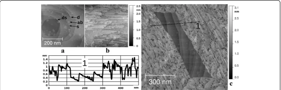
First, we survey the surface morphology of Ru(0001) with and without the oxide film. Throughout this work, we consistently present only those locations on our sam-ple, which did not include any step-bunching regions. The STM images (430 nm × 430 nm) of “metallic” and “oxidic” morphologies are presented in Fig. 1a–b. In Fig. 1a, we observe a typical Ru(0001) surface, exposing terraces separated mostly by single atomic steps“s”or in some cases double atomic steps“ds”; also visible are the screw dislocations “d”coming out at the surface. On the top of atomically flat terraces, we notice irregularly placed and shaped elevations “ab”, which closely resem-ble elevations above the buried argon bubresem-bles after simi-lar preparation of Ru(0001) reported by Jakob et al. [22] to be stable up to 1200 K. However, we could not detect the Ar 2p emission by means of XPS, as the total Ar concentration is most probably not high enough to reach above the noise level of our measurement. Never-theless, we tentatively associate the “ab” type features with argon bubbles trapped below the surface as a result of Ar+ion sputtering preparation step. It is worth noting that other impurities of relevance to our experiments produce different types of morphological features on the Ru(0001) surface, as demonstrated for carbon in [3, 4] and for oxygen below. In Fig. 1b, we show a typical sur-face of the RuO2(110) film, consisting of numerous
atomically flat terraces, single atomic steps, and holes with lateral extensions in the 10 nm range. Clearly, a nanostructured surface is created in this case as a result of the oxidation process.
Figure 1c presents an STM image of the 860 nm × 860 nm surface area of the partially oxidized sample with RuO2(110) present on the periphery and
non-oxidized atomically flat Ru(0001) in the center (paral-lelogram-shaped patch). This morphology is in line with the corresponding LEEM results, showing the growth of RuO2(110) domains with three distinct orientations
along the high symmetry directions of the Ru(0001) surface [15, 16]. The parallelograms can arise when the surface is not yet completely covered by the oxide and four domains of two different orientations (in al-ternating order) form a closed contour around an in-ternal metallic patch.
A cross-section along the black dashed line in Fig. 1c is given in the lower left part of the figure showing the height jump of ~0.6 nm between the oxide and the metal. This value is not identical to the oxide film thick-ness because the oxygen penetration into the ruthenium during the growth process will shift the oxide/metal interface below the unreacted metal surface. Another in-teresting feature, that can be deduced from this cross-section is that the basements of the holes within the oxide film often reach down to the non-oxidized Ru(0001). This means that such holes are essentially nanoscale perforations of the RuO2(110) film; thus, the
overall surface is strongly heterogeneous (metallic vs ox-idic) both at the micro and the nanoscale.
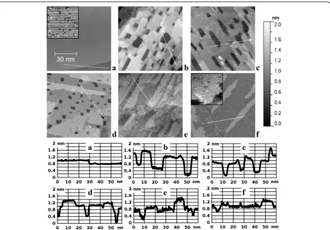
Next, we study the various stages of oxide growth, which are summarized in Fig. 2, starting from the initial atomically flat metallic substrate (a) followed by the iso-lated oxide patches (b–d) and finally the formation of a continuous oxide film (e, f ). The depicted sequence rep-resents essentially a film growth process with a simul-taneous consumption of substrate material. It starts on a metallic substrate with atomically flat terraces separated by single atomic steps (Fig. 2a), when there are only O atoms on the surface in the form of the 2 × 2 phase. This is the lowest coverage oxygen phase on Ru(0001) with a total coverage of 0.25 ML and a lateral distance between neighboring O atoms equals to 0.54 nm [7, 23], being re-solved in the 17.2 nm × 17.2 nm STM image (see inset in Fig. 2a).
When the oxide film appears on top of the substrate (Fig. 2b), it has nanoscale perforations, as already dis-cussed in Fig. 1b, c. As the amount of oxide increases, the perforations become smaller in lateral dimensions (Fig. 2b–d). At this growth stage, the film is essentially nanostructured in the form of apertures up to ~10 nm in lateral size and up to ~1 nm in depth. Finally, the per-forations vanish, and the film becomes continuous (Fig. 2e). At the final growth stage, there is a smoothen-ing of the surface, leadsmoothen-ing to the formation of extended atomically flat RuO2(110) terraces (Fig. 2f ), and the film
is no longer nanostructured. The corresponding atomic scale STM image is presented in the inset in Fig. 2f. Vis-ible here are rows of the so-called bridging O atoms, which are the topmost atoms of the given stoichiometric RuO2(110) surface [13]. These parallel rows run along
the [001] direction at a distance of 0.64 nm and are clearly resolved in the image. The neighboring O atoms within a row are only 0.31 nm apart and are barely re-solved as the atomic corrugation along the rows is roughly at the noise level of our measurement.
Provided the oxide film is present on the surface, we focus now on the changes of the film’s structure (par-ticularly nanostructure) induced by interaction with a re-ducing agent (carbon monoxide (CO)). In Fig. 3, the STM images in the left column (a, c, e) depict the initial state of the oxide film and those in the right column (b, d, f ) the final state after the complete or partial oxide re-duction. In Fig. 3a, we observe a smooth and continuous RuO2(110) similar to that in Fig. 2f, while shown in
Fig. 3b is the same sample after exposure to 10 L of CO at 600 K. The result of CO exposure is again a nanos-tructuring of the initially smooth surface, namely, some shallow (not through the entire film) pits with lateral sizes in the nanometer range that are etched out amidst
Fig. 1STM images (sample bias voltage 1.0 V; tunneling current 1 nA) of the single crystal Ru(0001).aPrepared according to the ion
[image:3.595.57.540.88.244.2]the formerly flat areas. Also, the topmost narrow ter-races are completely converted to aggregates of metallic nanoclusters, as they are attacked by CO molecules at their perimeter, and the reduction reaction spreads par-allel to the surface. Shown by black arrows is the corres-pondence between different types of areas before and afer the reduction.
In Fig. 3c, the initial state is non-continuous (nanoper-forated film), and the result of a similar exposure (10 L CO at 600 K) is shown in Fig. 3d. Now, the major effect is lateral widening of the holes (some of them now reaching several dozen nanometers); in other words, we observe lateral etching, which proceeds isotropically in the surface plane. Much higher exposure (100 L CO at 600 K) had an effect of complete oxide film reduction, as demonstrated by the sequence from Fig. 3e to Fig. 3f. The latter STM image shows the surface with numerous single atomic layer islands and pits of several nanome-ters in their lateral size, observed in the right part of Fig. 3f. However, in the left part of Fig. 3f, we observe the same morphology and structure as in Fig. 2a,
indicating the presence of the oxide-free patch prior to reduction. It seems like a natural explanation that the exact area imaged in Fig. 3f consists of both an oxide-covered patch (right) and oxide-free patch (left) prior to reduction. Again, the pairs of black arrows express the correspondence between these two types of areas before and after the reaction with CO. The border between these two patches is a section of the parallelogram’s per-imeter (of the one similar as in Fig. 1c or the one par-tially imaged in Fig. 3e). If viewed on atomic scale, both types of areas in Fig. 3f show the same 2 × 2 superstruc-ture as the inset in Fig. 2a.
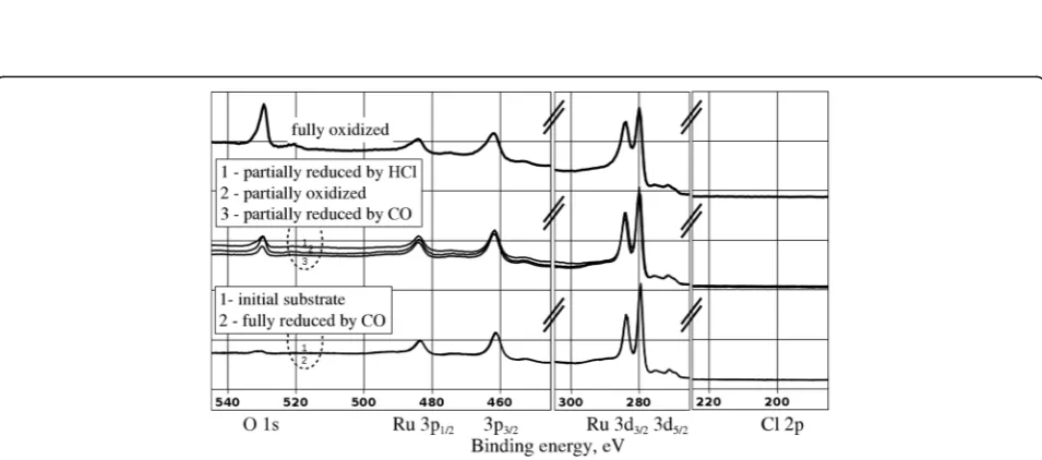
The STM data presented above provide an in-depth characterization of the surface morphology after certain well-defined chemical treatments of the Ru(0001) sub-strate. In order to verify the elemental composition of the surface, we performed the XPS characterization of our sample after selected preparation protocols. In Fig. 4, we present the XPS data gathered on the initial ruthe-nium substrate, after its partial or full oxidation, as well as partial or full reduction. Visible are the spectral
Fig. 2STM images (86 nm × 86 nm, sample bias voltage 1.0 V, tunneling current 1 nA) of the single crystal Ru(0001) sample at different stages of oxide film growth.aThe initial atomically flat metallic substrate;b–fthe oxide film grown at 630 K in O2at 3 × 10⁻⁵mbar duringb30 min,c 40 min,d50 min,e1 h, andf1.5 h. All images share the same gray scale ruler given to the right. The height–distance cross-sections along the dashed lines are presented in the lower part of the figure. The insets inaandfare 17.2 nm × 17.2 nm images with atomic resolution
[image:4.595.60.538.86.419.2]Fig. 3STM images (86 nm × 86 nm, sample bias voltage 1.0 V, tunneling current 1 nA) of the RuO2(110)/Ru(0001) sample before (a,c,e) and after (b,d,f) being chemically reduced:b,dafter exposure to 10 L (1 × 10⁻⁷mbar for 100 s) of CO, while the sample was held at 600 K;fafter exposure to 100 L (1 × 10⁻⁶mbar for 100 s) of CO, while the sample was held at 600 K. All images share the same gray scale ruler given to the left. The height–distance cross-sections along thedashed linesare presented in the rightmost column of the figure
[image:5.595.54.540.88.399.2] [image:5.595.59.537.453.664.2]features of the Ru 3p1/2, 3p3/2, 3d3/2, 3d5/2, and O 1 s emissions. In the lowest group of two spectra, the“initial substrate” spectrum was taken on the surface shown in Fig. 2a. Apart from ruthenium peaks, we also observe a very weak emission in the O 1 s region, corresponding to the 0.25 ML of O atoms chemisorbed on top of ruthe-nium (2 × 2 superstructure, see inset in Fig. 2a).
In the middle group of curves, a spectrum code-named as “partially oxidized” was obtained on the sam-ple shown in Fig. 2b. Here, the O 1 s emission is present in the spectrum at the level typical for the non-continuous (nanoperforated) RuO2(110) film. The
sam-ple with a continuous atomically flat oxide film (shown in Fig. 2f ) produced a photoelectron spectrum shown by the upper curve in Fig. 4, designated as “fully oxidized”. Its hallmark is the O 1 s emission of the intensity higher than the Ru 3p peaks and comparable with those from the Ru 3d core levels.
Further, we have acquired the XPS spectrum after par-tial reduction of the oxide film by CO, designated as “par-tially reduced by CO” in the middle group of curves in Fig. 4 and corresponding to the surface depicted in Fig. 3d. Here, the O 1 s emission has a similar intensity as that from the as-grown“partially oxidized” sample, consistent with the incomplete coverage of the surface by the oxide in the corresponding STM images. Finally, the spectrum obtained after complete reduction of the oxide in CO can be found in the lower group of curves (marked“fully re-duced by CO”). Notably, this spectrum is basically identi-cal to the“initial substrate”in the lower group of curves. It was obtained on the surface shown in Fig. 3f thus com-pleting the full circle: metallic surface–metal partially cov-ered by oxide–metal fully covcov-ered by oxide–metal partially covered by oxide-metallic surface. Under the “metallic surface,” we mean the Ru(0001) surface with chemisorbed 0.25 ML of oxygen forming the 2 × 2 super-structure. The return to this surface condition is evi-denced by STM (Fig. 3f) and identical O 1 s emissions in the lower group of curves in Fig. 4. Overall, we observe an excellent correlation between the intensity of the O 1 s
emission and the amount of oxide-related morphological features on the surface of our Ru(0001) sample.
Finally, we compare the above described reduction process induced by CO with that caused by interaction with HCl molecules. For this purpose, we have exposed the sample shown in Fig. 2e to 10 L (1 × 10⁻⁷
mbar for 100 s) HCl at substrate temperature of 700 K. The cor-responding XPS spectrum is marked as “partially re-duced by HCl”in the middle group of curves in Fig. 4. It is worth noting that no Cl 2p emission is visible in the spectrum after partial reduction by HCl. A separate ana-lysis has indicated that this emission is actually present but its intensity is very small. Thus, we can neglect the presence of chlorine on the surface, which stands in line with its release into the gas phase during the RuO2
re-duction above 650 K [24].
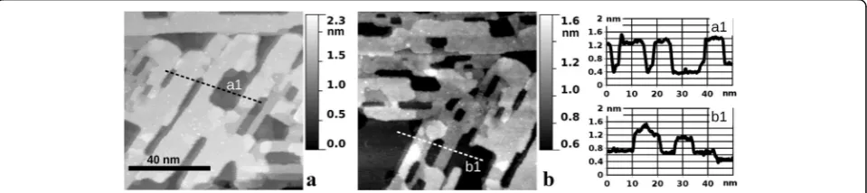
The STM images of the oxide film partially reduced by HCl are depicted in Fig. 5. Obviously, the initially con-tinuous film (Fig. 2e) becomes nanostructured in the form of nanoperforations. In Fig. 5a, the perforations are different from the cases of as-grown or CO-etched oxide by an apparent elongated shape in the direction coinci-dent with the rows of bridging O atoms. This is an indi-cation of the preferential sidewall etching of the RuO2
grains along the [001] direction or its equivalents. Since such directions are parallel to the sides of the “parallelo-grams”(as in Fig. 1c), it is natural to expect their preser-vation during the reduction process. Indeed, such parallelogram-shaped extended oxide-free areas were found on the given sample, and one of them is partially imaged in Fig. 5b. In this STM image, the gray scale is specially tuned to the height of the remaining RuO2
sur-face. The latter consists of atomically flat terraces, simi-lar to that after partial reduction by CO, with [001] rows of bridging O atoms still recognizable although with a noticeable degree of disorder on the atomic scale. The major difference between the interaction of RuO2(110)/
Ru(0001) and both reducing agents (CO and HCl) is thus the laterally isotropic vs anisotropic spreading of the reaction front. One possible explanation is a higher
Fig. 5STM images (86 nm × 86 nm, sample bias voltage 1.0 V, tunneling current 1 nA) of the RuO2(110)/Ru(0001) sample after being chemically reduced by exposure to 10 L (1 × 10⁻⁷mbar for 100 s) of HCl, while the sample was held at 700 K.aAn area which was covered by the oxide homogeneously before the reduction.bAn area which partially contains the parallelogram-shaped metallic patch prior to reduction
[image:6.595.59.539.587.694.2]mobility of the chlorine ions along the [001] direction. Further investigations will be required in order to obtain a complete picture of RuO2reduction by HCl, including
the initial stages as well as complete reduction and their corresponding surface morphologies.
Conclusions
In conclusion, we have identified by means of STM in-vestigation a variety of Ru(0001) oxidation and RuO2(110)/Ru(0001) reduction processes leading to
nanostructured (and/or heterogeneous) surfaces when started from atomically smooth morphology of the chemically homogeneous sample. The oxide growth at 650 K in O2proceeds through the nanostructured stage
later reaching an atomically flat surface of the saturated RuO2(110) film. The nanostructuring appears in the
form of irregular nanoscale perforations within the oxide layer, while their lateral sizes can be further manipulated (increased) by partial oxide reduction in CO (at 600 K) or HCl (at 700 K) gaseous environment. Our preliminary investigations demonstrate the “etching” of RuO2 by
HCl, which proceeds anisotropically in the surface plane, as opposed to isotropic etching by CO.
Abbreviations
STM:Scanning tunneling microscopy; UHV: Ultra-high vacuum; XPS: X-ray photoelectron spectroscopy
Authors’Contributions
Both authors have contributed equally to the present work. Both authors read and approved the final manuscript.
Competing Interests
The authors declare that they have no competing interests.
Author details
1Department of Physical Electronics, Taras Shevchenko National University of Kyiv, Glushkova 4G, Kyiv 03022, Ukraine.2Department of Physical Chemistry, Justus Liebig University, Heinrich Buff Ring 17, 35392 Giessen, Germany.
Received: 13 October 2016 Accepted: 24 November 2016
References
1. Over H (2012) Surface chemistry of ruthenium dioxide in heterogeneous catalysis and electrocatalysis: from fundamental to applied research. Chem Rev 112:3356–3426
2. Goriachko A, He Y, Knapp M, Over H, Corso M, Brugger T, Berner S, Osterwalder J, Greber T (2007) Self-assembly of a hexagonal boron nitride nanomesh on Ru(0001). Langmuir 23:2928–2931
3. Marchini S, Günther S, Wintterlin J (2007) Scanning tunneling microscopy of graphene on Ru(0001). Phys Rev B 76:075429
4. Kutana A, Goriachko A, Hu Z, Sachdev H, Over H, Yakobson B (2015) Buckling patterns of graphene–boron nitride alloy on Ru(0001). Adv Mater Interfaces 2:1500322
5. Goriachko A, Over H (2009) Modern nanotemplates based on graphene and single layer h-BN. Z Phys Chem 223:157–168
6. Goriachko A, Melnik PV, Nakhodkin MG, Zakharov AA, Over H (2013) Hexagonal C and BN superstructures on Ru(0001) and Ge(111). Mat-wiss u Werkstofftech 44:129–135
7. Meinel K, Wolter H, Ammer C, Beckmann A, Neddermeyer H (1997) Adsorption stages of O on Ru(0001) studied by means of scanning tunnelling microscopy. J Phys Condens Matter 9:4611–4619
8. Corriol C, Calleja F, Arnau A, Hinarejos JJ, de Parga AL V’z, Hofer WA, Miranda R (2005) Role of surface geometry and electronic structure in STM images of O/Ru(0001). Chem Phys Lett 405:131–135
9. Kim YD, Wendt S, Schwegmann S, Over H, Ertl G (1998) Structural analysis of the pure and cesiated Ru(0001)–(2 × 2)-3O phase. Surf Sci 418:267–272 10. Lizzit S, Baraldi A, Groso A, Reuter K, Ganduglia-Pirovano MV, Stampfl C,
Scheffler M, Stichler M, Keller C, Wurth W, Menzel D (2001) Surface core-level shifts of clean and oxygen-covered Ru(0001). Phys Rev B 63:205419 11. Stampfl C, Schwegmann S, Over H, Scheffler M, Ertl G (1996) Structure and
stability of a high-coverage (1 × 1) oxygen phase on Ru(0001). Phys Rev Lett 77:3371–3374
12. He YB, Knapp M, Lundgren E, Over H (2005) Ru(0001) model catalyst under oxidizing and reducing reaction conditions: in-situ high-pressure surface X-ray diffraction study. J Phys Chem B 109:21825–21830
13. Over H, Kim YD, Seitsonen AP, Wendt S, Lundgren E, Schmid M, Varga P, Morgante A, Ertl G (2000) Atomic-scale structure and catalytic reactivity of the RuO2 (110) surface. Science 287:1474–1476
14. Madhavaram H, Idriss H, Wendt S, Kim YD, Knapp M, Over H, Aßmann J, Loffler E, Muhler M (2001) Oxidation reactions over RuO2: a comparative study of the reactivity of the (110) single crystal and polycrystalline surfaces. J Catal. doi:10.1006/jcat.2001.3281
15. Flege JI, Sutter P (2009) Nanoscale analysis of Ru(0001) oxidation using low-energy and photoemission electron microscopy. J Phys Condens Matter 21:314018 16. Goritzka JC, Herd B, Krause PPT, Falta J, Flege JE, Over H (2015) Insights into
the gas phase oxidation of Ru(0001) on the mesoscopic scale using molecular oxygen. Phys Chem Chem Phys 17:13895
17. Herd B, Knapp M, Over H (2012) Atomic scale insights into the initial oxidation of Ru(0001) using molecular oxygen: a scanning tunneling microscopy study. J Phys Chem C 116:24649–24660
18. Herd B, Goritzka JC, Over H (2013) Room temperature oxidation of ruthenium. J Phys Chem C 117:15148–15154
19. Herd B, Over H (2014) Atomic scale insights into the initial oxidation of Ru(0001) using atomic oxygen. Surf Sci 622:24–34
20. Kim SH, Wintterlin J (2009) Morphology of RuO2(110) oxide films on Ru(0001) studied by scanning tunneling microscopy. J Chem Phys 131:064705 21. Dudin P, Barinov A, Dalmiglio M, Gregoratti L, Kiskinova M, Goriachko A,
Over H (2008) Nanoscale morphology and oxidation of ion-sputtered Rh(110) and Ru(0001). J Electron Spectrosc Relat Phenom 166–167:89–93 22. Jakob P, Gsell M, Menzel D (2001) Interactions of adsorbates with locally
strained substrate lattices. J Chem Phys 114:10075–10085
23. Calleja F, Arnau A, Hinarejos JJ, de Parga AL V’z, Hofer WA, Echenique PM, Miranda R (2004) Contrast reversal and shape changes of atomic adsorbates measured with scanning tunneling microscopy. Phys Rev Lett 92:206101 24. Zweidinger S, Hofmann JP, Balmes O, Lundgren E, Over H (2010) In situ
studies of the oxidation of HCl over RuO2 model catalysts: stability and reactivity. J Catal 272:169–175
Submit your manuscript to a
journal and benefi t from:
7Convenient online submission 7Rigorous peer review
7Immediate publication on acceptance 7Open access: articles freely available online 7High visibility within the fi eld
7Retaining the copyright to your article