HP 9800 Computers
98750 CE Handbook
Part No. 98750-90039 E0982 Requires Binder No. 9282-0683
Flin-
HEWLETTa:~ PACKARD
98750 CE Handbook
© Copyright Hewlett-Packard Company, 1982
This document refers to proprietary computer software which is protected by copyright All rights are reserved. Copying or other reproduction of this program except for archival purposes is prohibited without the prior written consent 01 Hewlett-Packard Company
Hewlett-Packard Company
( h 'I\f" I 'JS-;-,() 1'1 "d\l( I Ilt""lldl","
( h 'I t, I '!
11K, )(J t ,,\II,lIllllIll1dlll' .... ",lIdIH\11 P\l
~ 1"'1,1, I \
' " I I t \ '1
~ h , I f r 1
j~ 'U l<Ul.lll.. ... lluululq
t tltlf)itJ-'
'." ! \ ! \ ) .
( h"pll'If>
'IKj-,(I \d,,'~III" III~
(1"'I,t(1 -; (IS,-,(i !'< IIpl1! I"I~
( I'''ph I S
'IS7 ,0 HI pi,,, I'IIl! lit 1',lIt,
t h,lpll'l 'I (IS 7:)0 iJld'll ""1~
l 11''1>11'1 \0
'Isr)() Hdl'l"III"
( l I ! I I
98750 Product Information 1-1
Chapter
1
Product Information
CRT Display Specifications
Screen Size: Refresh Rate: CRT Phosphor: Alpha Raster: Character Size: Screen Capacity: Graphics Raster:
261 mm x 193 mm (10.3 x 7.6 inches) 60Hz
P31
236 mm x 123 mm (9.3 x 4.84 inches) 2.3 mm x 2.95 mm (.09 x .116 inches) 24 lines of 80 characters
200 mm x 162.5 mm (7.9 x 6.4 inches)
Options and Configurations
The 98750A is available as an integral part of the 9845B #lxx. See the 9845B Base CE Handbook Chapter for option information.
09845-92030 09845-93050 09845-92005
Related Documentation
Service Manual
Monochromatic Graphics Programming Manual Owner's and System Exerciser Manual
Product Support Package
The 98750A service tools are included in the 9845B Product Support Package. Refer to the 9845B CE Handbook Chapter.
Safety
WARNING
98750 Environmental/Installation/PM 2-1
Chapter
2
Environmental/Installation!
Preventive Maintenance
Installation
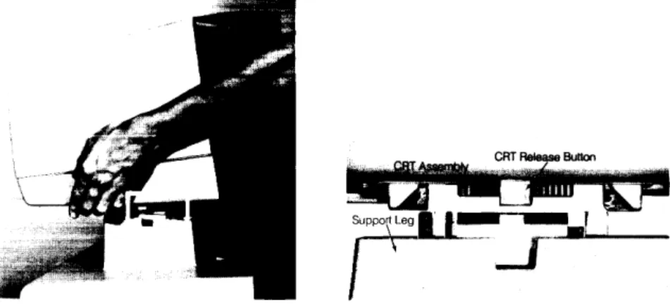
After unpacking the computer, the CRT assembly must be mounted onto the mainframe assembly. The CRT assembly will lock into place on top of the mainframe support legs. It is important that the gUides on the CRT assembly and the mainframe support legs are aligned properly before assembly. Figure 2-1 shows the proper alignment necessary for the CRT assembly installation. Notice how the buttons on bottom of the CRT assembly align with the notches in the support legs.
2-2 98750 Environmentalilnstallation/PM
Preventive Maintenance
Base Configuration
98750 Configuration 3-1
Chapter
3
Configuration
The following assemblies must be installed in the 9845B base to support the98750A.
09845-65517 1818-0831 and 1818-0835
09845-66503
Graphics ROM
Mainframe ROM for Graphics ROM Mainframe ROM for Graphics ROM Alpha Control Assembly
Refer tothe 9845BBase CE Handbook Chapter for the locations of these parts.
Interfacing
3-2 98750 Configuration
Status Word
The Status Word may be obtained by executing the following instructions:
STATUS 13 iA
DISP A
The result is a decimal integer which may be converted to binary and interpreted as shown below.
4 o
1101011101010010
LID
BitCheck
Is the base operating? (Try PRINTER IS 0
PRINT "HELLO")
Is there any display?
Adjust intensity control. Press control-stop. Is there a cursor?
Press A76 Test Button. Does a raster appear?
Initial Checks
98750 Troubleshooting 4-1
Chapter
4
Troubleshooting
Action
Yes - Proceed with Initial Checks. No - Fix base.
Yes - Proceed to Diagnostics. No - Proceed with Initial Checks.
Yes - Proceed to Diagnostics. No - Proceed with Initial Checks.
Test Summary
98750 Diagnostics 5-1
Chapter
5
Diagnostics
The CRT Tests are contained on the 9845B Test Binary Cartridge or the 9845A Test ROM. For the 9845B, insert the cartridge, and enter:
LOADBIN "TBIN"
For the 9845A. install the Test ROM and turn power on.
Press kO for the CRT alpha tests or k5 for the CRT Graphics tests. Follow the instructions for each test. as follows.
KO CRT Alpha Test
This test will check and exercise all the CRT alpha functions and provide test patterns for the following CRT adjustments:
• Focus
• Alpha raster size
The adjustment procedures are found after this test procedure.
T a exit this test press ( STOP).
Press
CJLJ;
the CRT displays:Press B For full buffer H For He He
L For Linearit~'
G Graphics
C For Character Set
o
For Optional Char. Set5-2 98750 Diagnostics
Press
CD ;
the CRT displays:A failure on ths display indicates a probable A 73 assembly failure.
Press
o=J ;
the CRT displays:Usc th:s patte!'n to adjust the focus:ng adjustment (desc!':bed after th:s test) unt:! the "H"
98750 Diagnostics 5-3
Press
CJ::J;
the CRT displays:Press
o:J :
if the graphics option is installed, a full screen graphics cursor is displayed and the computer is in the graphics mode. See the Graphics section for details.Press ( STOP) to exit the graphics test and return to the CRT Alpha Test.
If the graphics option is not installed, the G key will be ignored.
5-4 98750 Diagnostics
The character set is repeated five times. This test exercises all the CRT features. If the pattern is deformed, the A 73 assembly may be defective.
Press
o:J ;
the CRT displays the optional characters if the option ROM is installed. When the option ROM is not installed the CRT shows: -111111111111111111111111111111111111111111111111111111111111111111111111111111 111111111111111111111111111111111111111111111111111111111111111111111111111111 '1111111111111111111111111111111111111111111111111111111111011111111111111111. 111111111111111111111111111111111111111111111111111111111111111111111111111111 111111111111111111111111111111111111111111111111111111111111111111111111111111Press
CO;
all the CRT display features can now be checked. The CRT displays:PRESS CONTINUE
Press (CONTINUE) 15 times, noting each time the feature being displayed. The features are shown in the folloWing order.
inverse video normal blinking video normal video underlined normal video with cursor blinking inverse video underlined inverse video inverse video with cursor blinking inverse video underlined inverse video with underline and cursor blinking inverse video with cursor
blinking inverse video with underline and cursor blinking video and underline
98750 Diagnostics 5-5
K5 CRT Graphics Test
This test checks the 32k-byte graphics memory and tests all the CRT graphics commands.
Press
L..&J,
the graphics memory test runs automatically. The test lasts about one minute. To exit the graphics memory test before it is completed, press (CONTINUE). Errors in the graphics memory test are displayed, for example:G RA PH! C S (octal address) HAS (octal patern) NOT (octal pattern)
When the graphics memory test is completed manual control of the cursor and display is enabled. Here is a description of the control features and the key to press for each feature.
~ Moves the cursor to the left.
~ Moves the cursor to the right.
(=cJ
Moves the cursor up.CIJ
Moves the cursor down.CD
CO
CD
CD
CD
NotePressing the above keys once moves the cursor one step. Pressing the keys all the way down moves the cursor ten steps at a time.
A box outlining the graphics raster is displayed.
Causes three different cursors to appear. One type is displayed each time
CI:J
is pressed. PressCI:J
three times to view the cursors listed below.The alpha cursor (-). The graphics cursor (+ ).
The full screen graphics cursor.
Clears the display. Pressing ( SHIFT) at the same time clears the display faster. Fills the entire display with dots.
Displays grid referenced from the current X, Y position of the cursor.
Causes any function being performed to loop or be performed continuously until
CD
is pressed again.Displays the cursor position on the display and the corresponding position in memory. To continue press another key.
Random pattern check.
Skip a particular test. (exits the graphics test) Exits the graphics memory test.
Begins the graphics memory test. Walking bit test.
Places the cursor in the center of the display. ( SHIFT)
( I )
moves the cursor off the display.Press any key to continue after an error occurs.
To exit the test, press ( STOP) once to stop the operation then press ( STOP) again to exit the graphics test.
CRT Display Focus
98750 Adjustments 6-1
Chapter
6
Adjustments
The focus should be checked whenever the A7S or the CRT/yoke assembly has been changed.
The focus control is located on the A 75 assembly inside the high voltage cage. Remove the CRT top cover and the high voltage cage cover to access the A75 assembly (see Figure 6-1).
Display a full raster pattern of characters; the test ROM CRT alpha test will provide these patterns. Adjust the focus control to sharpen the appearance of the displayed characters. It may not be possible to focus all areas of the display at a particular control setting; in this case, the focus control should be set at the point that gives the best overall display appearance.
CRT Intensity
The intensity should be checked whenever the A75 or the CRT/yoke assembly has been changed.
The intensity control is located on the A 75 assembly inside the high voltage cage. Remove the CRT top cover and the high voltage cage cover to access the A75 assembly (see Figure 6-1).
To adjust the CRT intensity, use the following procedure.
1. Advance the A75 intensity control and the operator's intensity control on the lower right
corner of the CRT bezel to maximum intensity.
2. With both controls at maximum settings, horizontal retraces should appear on the CRT. Adjust the A 75 intensity control until the retraces are no longer visible.
3. Press the CRT test button and notice the intensity of the full raster display.
4. Use the A 75 intensity control to reduce this intensity by approximately 1fz. This control
setting is between l/s and 1/4 of a turn less on the A75 intensity control.
5. Adjust the operator's intensity control for the desired intensity. 6. Reassemble the computer.
CRT Alpha Raster Size
The alpha raster size should be checked whenever one of the CRT section assemblies has been changed. To adjust the alpha raster, use this procedure.
• Remove the CRT top cover.
• Press the CRT test button on the A73 assembly, shown in Figure 6-1, to display the alpha raster in inverse video.
• Use the alpha width and alpha height controls on the A74 assembly to adjust the edges of
6-2 98750 Adjustments
CRT Graphics Raster Size
To adjust the graphics raster use this procedure: • Remove the CRT top cover.
• Install the test binary cartridge and switch the power switch to on. • Answer the questions and press k5 when its time to select a function key.
• Use the graphic width and graphic height controls on the A 7 4 assembly to align the edges of the inverse video to the graphics raster outline on the CRT alignment mask. Use the raster dimensions given in the specifications in chapter 1.
Display Logic CRT Test
Graphics Height Control A7409845-66574 CRr Analog A7509845-66575 High Voltage Assembly A7609845-66576 Interconnect Assembl (Located On Bottom Side Of A71 Assembly)
Figure 6-1
High Voltage Cage
A 71 09845-66571 CRT Motherboard A77 09845-66577 Graphics Scanner CRT Yoke' A 76 09845-66576 Interconnect Assembly (Located On Bottom Side Of A71 Assembly) A7909845-66579 GraphiCS Memory CRT Bottle' CRT Bezel
98750 Peripherals 7-1
Chapter
7
98750 Replacement Parts 8-1
Chapter
8
Replaceable Parts
Repair Philosophy
Most 98750A repairs are done by replacing the faulty assembly. The old assembly is returned for repair in some cases (exchange program) and is thrown away in others. In a few cases, a faulty assembly can be repaired to the component level either on-site or at the local field office. This procedure is recommended only when replaceable components are not soldered in or when the probability of inducing further damage in the course of doing the repair is minimal. All components which may be replaced by the CE are listed as level 2 parts under the assembly part number in the parts lists. Other failures should be repaired at the assembly level. All exchange parts are noted as such in the parts lists.
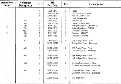
Table 1: Replaceable Parts List
Assembly Reference CD HP TQ
Description Level Designator Part No.
1 6 0960-0480 1 TripIer
I 4 0':11;45-26576 2 CRT Interface PC board
1 4 09845-61671 1 Intensity Control Cable
1 5 09845-61672 1 Tube Socket Cable
1 A71 3 0984566571 1 Motherboard
1 A72 4 09845-66572 1 Power Transistor Assy
2 Q4 5 1826-0169 1 Voltage Regulator - LM320K-15
2 Ql H 1826-0203 I Voltage Regulator - 7815KC
2 Q2.3 H 1853-0305 2 TranSistor - 2N5875
2 Q6 7 18540518 1 Transistor·2N5877
2 Q5 8 1854-0783 1 Transistor - 2N6583
1 A73 5 09845-66573 1 Display Logic Assy. - New
1 09845-69573 Display Logic Assy - Exchange
1 A74 6 09845-66574 1 CRT Analog Assy - New
2 09845-69574 CRT Analog Assy ~ Exchange
1 A75 7 09H45-66575 1 High Voltage Assy - New
3 09H45-69575 High Voltage Assy Exchange
1 A77 9 09845-66577 1 Graphics Scanner Assy - New
5 09845-6% 77 Graphics Scanner Assy - Exchange
1 A79 1 09845-66579 1 Graphics Control Assy - New
7 09845-6%79 GraphiCS Control Assy - Exchange
1 0 09845-67972 1 CRT Yoke Assy
A7509845-66575 High Voltage
A7409845-66574 CRT Analog
A73 09845-66573 Display Logic
98750 Diagrams 9-1
Chapter
9
CRT Section (Alpha)
A7209845-66572 Regulator Assembly
Diagrams
._---4--+--f"-t--A71 09845-66571 CRT Motherboard
~~I--~-CRT Yoke Assembly
Graphics Section
A77 09845-66577 Graphics Scanner A7909845-66579 Graphics Memory
TOAI61
~~R6~~~:~~ I CRT Control Logic
UNIT I
I I I
i
DATA ---REGI~TER_ _ _ _ _ _ _ _ _ _ _ _ ----.J
TO PPU A16
PA0-PA3
INT OOUT
ICI IC2
A79 CONTROL ASSY
I/O
ROY
I A77 SCANNER ASSY TO CRT
ALPHA DISPLAY h - - - . CIRCUITS
MEM
- - - 1
View From InSIde The Rear Panel.
+ laV From
Power Supply
-lav From
Power Supply - - - - . J - .. .. ...
-15VToA74 \ ... !l ...
andA75
\,,-~
"
.... .... : ...\ 04
'. ---:.:': _':-GrOUnd
.:-
....:
...\,''' ... ~ +6VFromA74
+5V From _
~
1.05powerSUPPlyJ " '<.: ... " \
I--Ground _ ,_... ... -.5 to +3V to
- l ... A74 and A75
\, ,/' - ... ,06
tC ~ r ' T O A 7 4
Fro~r~;~i~~ ~~~:ge ... .,../ \ ... _ ...
'
'_m
/,J--...
-.,...--=...,...
From A75 / + 300 Peaks
Flyback
Pulse
(Vo~s)
ToA74 -18
98750 Reference 10-1
Chapter
10
98750 Service Notes 11-1