Investigation of Structural Parameter of
Perforated Muffler for Performance Optimization
Using CFD Analysis
Krunal C. Chaudhari1, Prof. Shantanu. J. Chaudhari2
1Research Scholar, Mechanical Engineer, NMU, Jalgaon 2Asso. Prof. Automobile Engineering Dept., SGDCOE, Jalgaon
Abstract: In these research paper basic mufflers and its modifications and design of exhaust system belonging engine has been studied. The object of this study is deciding muffler design which one reduces a large amount of pressure of engine. In designing, there is different parameter which has to taken in to the consideration. These parameters affect the muffler efficiency. Internal combustion engines are typically equipped with an exhaust muffler to suppress the acoustic pulse generated by the combustion process. A high intensity pressure wave generated by combustion in the engine cylinder propagates along the exhaust pipe and radiates from the exhaust pipe termination. On the other hand, developments on automobile technology and increasing competition between manufacturers necessitates having being reduced weight, having capability of higher sound absorption and lower back pressure mufflers. Lightness could be possible if the thickness is decreased or the volume is reduced. However, this causes high back pressure. Therefore, the optimum design requires. Recently finite element methods are used to obtain flow characteristics and back pressure values of mufflers. Having used of this method, effect of different parameters can be examined without prototyping and best suitable muffler can be determined in the design process. Furthermore time and money can be saved.
I. INTRODUCTION
Internal combustion engines are generating the acoustic pulse by the Combustion process. This noise is controlled through the use of silencers and mufflers. A silencer has been the traditional name for noise attenuation devices, while a muffler is smaller, mass-produced device designed to reduce engine exhaust noise. Continuous development has been made in improving performance of the silencers used for automotive exhaust systems. Exhaust mufflers are widely employed to muffle the noise of an engine body or the noise of other predominant sources in vehicles. In order to maintain a desired noise and comfortable ride, the modes of a muffler need to be analyzed.
A. Reactive muffler
In this type of muffler Inlet and outlet tube are extended in chambers. Reactive mufflers generally consist of several pipe segments that interconnect with a number of larger chambers. The noise reduction mechanism of reactive silencer is that the area discontinuity provides an impedance mismatch for the sound wave travelling along the pipe. This impedance mismatch results in a reflection of part of the sound wave back toward the source or back and forth among the chambers. The reflective effect of the silencer chambers and piping (typically referred to as resonators) essentially prevents some sound wave elements from being transmitted past the silencer. The reactive silencers are more effective at lower frequencies than at high frequencies, and are most widely used to attenuate the exhaust noise of internal combustion engines.
B. Absorptive muffler
This type of muffler design uses only absorption of the sound wave to reduce the noise level without messing with the exhaust gas pressure. Ti is known as glass pack muffler and it reduces back pressure but producing higher noise. The sound produced by this type of muffler is much higher compared to the other type of mufflers.
C. Combination muffler
D. Problem Statement
here is an increasing awareness of noise pollution on the part of the general public in urban areas, especially noise caused by automotive. A pollutant of concern to the mankind is the exhaust noise in the internal combustion engine. However this noise can be reduced sufficiently by means of a well designed muffler. The suitable design and development will help to reduce the noise level, but at the same time the performance of the engine should not be hampered by the back pressure caused by the Muffler. In particular, users of certain types of general automotive may be compelled to restrict operations and/or modify their automotive to comply with existing or forthcoming noise legislation that will specify upper limits on external noise levels. Analysis of this noise indicated that engine-exhaust noise was the primary cause of both unacceptably high cabin-noise levels and radiated far-field noise.
II. BASIC REQUIREMENT OF MUFFLER DESIGN
A. General Requirements
1) Quiet
2) Simple maintenance
3) Performance
4) Compact design
5) Light weight
B. Specific Requirement
1) Reduce the sound emissions
2) Replaceable
3) Doesn’t increase backpressure
4) Easy mounting
5) Within the budget
6) Easy manufacturing
C. Functional Requirements of A Muffler
There are numerous functional requirements that should be considered when designing a muffler for a specific application. Such functional requirements may include adequate insertion loss, backpressure, size, durability, desired sound, cost, shape and style. These functional requirements are detailed below focusing on an automotive muffler’s functional requirements
Adequate Insertion Loss: The main functional of a muffler is to “muffle” or attenuate sound. An effective muffler will reduce the sound pressure of the noise source to the required level
1) Backpressure: Backpressure represents the extra static pressure exerted by the muffler on the engine through the restriction in flow of exhaust gasses. Generally the better a muffler is at attenuating sound the more backpressure is generated.
2) Size : The available space has a great influence on the size and therefore type of a muffler that may be used. A muffler may have its geometry designed for optimum attenuation however if it does not meet the space constraints, it is useless.
3) Durability: The life expectancy of a muffler is another important functional requirement especially when dealing with hot exhaust gasses and absorptive silencers that are found in performance vehicles. Aluminized vs. stainless are two types of steel commonly used to manufacture muffler. Stainless steel mufflers are considered more durable and can last up to 10 years. Aluminized mild steel mufflers are prone to corrosion, and therefore they typically last around 4 years.
4) Desired Sound: There has however been a growing trend in Australia in recent years for young drivers wanting to “hot up” their vehicles and this includes muffler modification. Muffler modification of a stock vehicle is generally done for two reasons being performance and sound.
6) Shape and Style: Automotive mufflers come in all different shapes, styles and sizes depending on the desired application. Generally automotive mufflers consist of an inlet and outlet tube separated by a larger chamber that is oval or round in geometry. The inside detail of this larger chamber may be one of numerous constructions.
III. INPUT PARAMETER
Engine Data: Bore (D) = 38.4 mm Stroke (L) = 43 mm No. Cylinders (n) = 1
Engine power (P) = 1.75 bhp at 3000 RPM
Muffler Volume Calculations: Swept volume per cylinder = (3.14 x 38.42 x 43) (Vs) = 0.199 lit.
Total swept volume in liters 0.199 Lit.
Volume to be considered for calculation = 0.5 x Vs x n= 0.0995 Lit
Silencer volume: Volume of silencer must be at least 12 to 25 times the volume considered. Volume can be adjusted depending on the space constraint.
Factor considered is = 12
Silencer volume = factor x consider volume = 1.1894 Lit For rectangular muffler L=200 mm, b=100mm
Width of Muffler Calculations: Vm = l x w x b. 0.001194= 0.25 x w x 0.10
w = 0.0476 m= 47mm Approximately w=50mm Diameter of Pipe Calculations:
As per the standards of the supercritical grade of mufflers, the width of the body should be about three times than the exhaust pipe diameter.
w = 3* d exhaust 50= 3* d exhaust d exhaust = 16.66 mm Material properties. Density : 4500 kg/m3 Specific heat : 550 J/(kg*K)
Thermal Conductivity : 16 W/(m*K) Conductivity type: Isotropic
Initial values for velocity inlet as the inlet boundary condition. Area : 0.002775 (m2)
Temperature: 450 (K) Viscosity: 2.7e-05 (kg/ms) Enthalpy: 749575.3 (J/kg) Density: 0.716 (kg/m3)
Length: 250(mm) Velocity: 1.85 (m/s) Ratio of specific heats : 1.4
A . Base case muffler
Outlet pipe Dia: 16.66 mm Outlet pipe length : 120mm
[image:5.612.165.449.283.458.2]Fig 1 CAD model of base case muffler
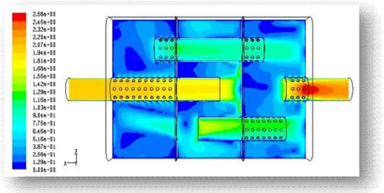
Fig 2 Velocity profile (m/s) of base case muffler
[image:5.612.152.457.499.709.2]Velocity Magnitude in m/s
Inlet 1.8590597
Outlet 1.8956855
Total Pressure (Pascal)
Inlet 8.398768
Outlet 3.248946
Pressure Drop
5.1498227
B. First Modification
Perforated outlet pipe inside expansion chamber in muffler Dimensional data
[image:6.612.167.446.574.714.2]Shell length: 250 mm Shell Width: 50 mm Shell breadth: 80 mm Inlet pipe Dia : 16.66 mm Inlet pipe length : 120 mm Outlet pipe Dia: 16.66 mm Outlet pipe length : 120mm
Fig 4 CAD model of perforated outlet pipe inside expansion chamber
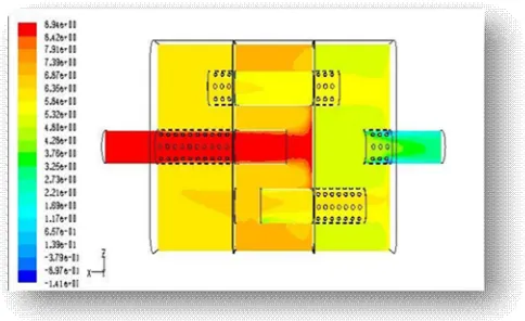
Fig 6 Pressure profile (Pa) of perforated outlet pipe inside expansion chamber
Velocity Magnitude in m/s
Inlet 1.8580784
Outlet 1.9165685
Total Pressure (Pascal)
Inlet 8.933359
Outlet 2.944832
Pressure Drop 5.9885275
C. Second Modification
All perforated tubes inside the expansion chamber of muffler Dimensional data
Shell length: 250 mm Shell Width: 50 mm Shell breadth: 80 mm Inlet pipe Dia : 16.66 mm Inlet pipe length : 120 mm Outlet pipe Dia: 16.66 mm Outlet pipe length : 120mm
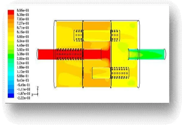
Fig 8 Velocity profile (m/s) of all perforated tubes inside the expansion chamber of muffler
Fig 69 Pressure profile (Pa) of all perforated tubes inside the expansion chamber of muffler
Velocity Magnitude in m/s
Inlet 1.8560767
Outlet 1.9965685
Total Pressure (Pascal)
Inlet 9.0613165
Outlet 2.4687803
Pressure Drop 6.5925362
IV. CONCLUSION Velocity Magnitude in m/s
Case
Pressure
Base case muffler Perforated outlet
pipe inside expansion chamber
in muffler
All perforated tubes inside the
expansion chamber of
muffler
Inlet 1.8590597 1.8580784 1.8560767
Total Pressure (Pascal) Case
Pressure
Base case muffler Perforated outlet
pipe inside expansion chamber
in muffler
All perforated tubes inside the
expansion chamber of
muffler
Inlet 8.398768 8.933359 9.0613165
Outlet 3.248946 2.944832 2.4687803
Pressure Drop
5.1498227 5.9885275 6.5925362
A. Output velocity increases in all perforated tubes inside the expansion chamber of muffler compared to perforated outlet pipe inside expansion chamber in muffler and base case muffler.
B. Exhaust pressure reduction in base case muffler is 61.31%
C. Exhaust pressure reduction in perforated outlet pipe inside expansion chamber in muffler is 67.03%
D. Exhaust pressure reduction in All perforated tubes inside the expansion chamber of muffler is 72.75%
E. Hence it conclude that all perforated tubes inside the expansion chamber of muffler is more efficient in reducing the exhaust pressure compared with perforated outlet pipe inside expansion chamber in muffler and base case muffler.
REFERENCES
[1] Min-Chie Chiu Long-JyiYeh, Ying-Chun Chang, Tian-SyungLan “Shape Optimization of Single-Chamber Mufflers with Side Inlet/Outlet by Using Boundary Element Method, Mathematic Gradient Method and Genetic Algorithm ”TamkangJournal of Science and Engineering, Vol. 12, No. 1, pp. 8598 (2009)
[2] S. N.Y. Gergesand R. Jordan “Muffler Modeling by Transfer Matrix Method and Experimental Verification”Federal Univ. of Santa Caterina Mechanical Engineering Dept CP 476 Florianópolis, Brazil
[3] Sudarshan Dilip Pangavhane ;AmolBhimraoUbale ; Vikram A Tandon ; Dilip R Pangavhane “Experimental and CFD Analysis of a Perforated Inner Pipe Muffler for the Prediction of Backpressure ”Sudarshan Dilip Pangavhane et.al / International Journal of Engineering and Technology (IJET).