Cyclic Prefix Based Channel Estimation of Single Carrier
-Frequency Domain Equalization
Smrati Singh Sachan
1, D r. A ni l K umar S harm a
21IET Alwar,Rajasthan,India,[email protected] 2IET Alwar Rajasthan,India,[email protected]
Abstract: For the mobile communication, single carrier cyclic prefixed (SC-CP) with frequency domain equalizer (FDE) is favourable and robust channel estimation. Conventional SC-CP wireless system uses training sequences that put in every packet to get the channel information. Channel State Information (CSI) is the crucial parameter that should be available at the receiver. Correct channel estimation is very important to the implementation of any communication system. In wireless communication system, data is often transmitted through unknown channel. This state of information is generally obtained at the receiver by sending training sequence from transmitter to receiver repeatedly and a training algorithm is performed by the receiver on the observed channel output and the known input to the channel. Since, training sequence is sent with the data frame, these solution results in loss of net throughput. A different way of obtaining CSI has been explored in this paper, making use of the transmitted information i.e. cyclic prefix itself and without adding any training symbols. This obviates the need for
training sequences and results in overall increase in throughput.
Keywords:Channel estimation, cyclic prefix, frequency domain equalization, single carrier, wireless.
1. I
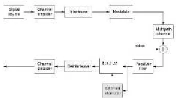
NTRODUCTIONThe wireless communication channels are generally multipath fading channels which cause Inter Symbol Interference (ISI) in the received signal. To compensate for this channel induced ISI, various equalizer are in use. However, the information about the channel is highly desirable for proper functioning of equalizer. General Method of obtaining Channel information in Fig 2 shows a generic communication system which exploits channel estimation and signal detection operations in equalization. The digital source is usually protected by channel coding and interleaved against fading phenomenon, after which the binary signal is modulated and transmitted over multipath fading channel. Additive noise is added and the sum signal is received. Due to the multipath channel there is some inter symbol interference (ISI)
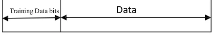
in the received signal. For successful equalization, channel state information need to be known. Traditionally, the channel estimation is based on the known sequence of bits, which is unique for a certain transmitter and which is repeated in every transmission burst. Thus, the channel estimator is able to estimate CSI for each burst separately by exploiting the known transmitted bits at the receiver and the corresponding received samples. These known sequences are called training sequences or training symbols. Every time a frame is transmitted, these training symbols are transmitted and form the preamble part of the frame.
[image:2.612.318.538.608.644.2]Training Data bits
Data
to -1.The last v symbols (from m-v to m-1) has been prefixed in the frame. The input to the receiver of SC- FDE can be expressed in the form of equation given
by
[image:3.612.88.264.159.258.2]y
Hx
V
n (1)Figure.2 Generic wireless system with Channel Estimator
Where x is the transmitted vector and y is the received vector and H is the Channel matrix. Now if we consider only the cyclic prefix part of the frame then
Fig 2 shows that data bits from signal source are encoded, interleaved and modulated. After modulation, it passes through the Multipath channel. Due to the multipath channel there is some inter- symbol interference (ISI) in the received signal. Here CSI is estimated based on the known training
sequence, which is transmitted in every transmission
y
cp
Hx
cp
V
nThe above equation can also be expressed as
y
cp
X
0h
V
n.(2)
(3)
burst as Fig.1. The receiver can utilize the known training bits CSI typically for each burst separately.
However, there in one drawback of above system that it consumes bandwidth with every frame transmitted.
Which is another way of expanding convolution,
where h is of length l and Xo is matrix containing cyclic prefix
symbols. Xohas dimensions of [v x l] where v is the cyclic prefix
length and represented as
x
vx
( v1)x
( v2 ).. ..
x
1
Every time a frame is transmitted, a large space is
occupied by the training symbols and hence the overallthroughput reduces.
0
x
(v1)
x
( v2 ).. ..
x
1
0
0
x
( v2 ).. ..
x
1
X
0
2. P
ROPOSED WORK2.1 Proposed Model for CSI in SC-FDE
:
:
:
.. ..
:
:
:
:
.. ..
:
In case of SC-FDE, a frame has the structure as
0
0
0
..
..
x
1
(4)
shown in fig 3 with every frame transmitted, a cyclic prefix is appended with every frame to maintain the
periodicity in the signal which has advantage.
Now estimation of channel h can be described through equation
ˆ
1h
X y
cp (5)
[image:3.612.45.543.449.704.2]n
This is the pseudo inverse matrix of Xo. In equation5, ycpis available to us at the receiver. Now in order to estimate the
channel through equation 5,
we need to know the entries in the matrix X-1 or basically the cyclic prefix symbols transmitted. Here, we will make use of equation 2 the estimate of x is
given by
is duplicity in the initial and last symbols of the frame which is the only information available to us here.
3. S
IMULATION RESULTx
ˆ
x
H
1V
2.2 Block Diagram of Proposed System
(7) 3.1 Flow Diagram
Channel estimation take palce when the last symbols of data block and prefixed symbols, both of these should be equal or the difference of them should be
[image:4.612.322.547.394.527.2]Here, we make use of the fact that the last v symbols of the frame are equal to the cyclic prefix part. That is true also since the last part of the frame has been prefixed at the input. In the received vector also, the last v symbols must be equal to first v symbols.
Figure 4 Block diagram of channel estimator in SC- FDE
Initially, assumption is made that channel coefficients are available to us. Based on this, the received symbols are equalized. Once these symbols are equalized, the first v symbols are extracted and put in equation and channel is estimated. Now based on the new channel estimated, again the received symbols are equalized; the first v symbols are extracted and compared with cyclic prefix part. The last symbols of data block and prefixed symbols, both of these should be equal or the difference of them should be equal to zero. This process is repeated again and again until we get those values of h coefficients for which the first and last part of the frame are equal or their difference is minimum. Once we reach that stage, that will be the correct estimate of h and the frame can be equalized with these coefficients. In the next operation, when new frame arrives at the receiver, the recent value of h is updated.
This way, it is possible to obtain channel state information. We have made use of the fact that there
equal to zero. This process is repeated again and again until we get those values of h coefficients for which the first and last part of the frame are equal or their difference is minimum. Once we reach that stage, that will be the correct estimate of h and the frame can be equalized with these coefficients. In the next operation, when new frame arrives at the receiver, the recent value of h is updated
Figure-5 Simulation Flow Diagram
3.2 Simulation Result
Here are results of the above explained algorithm for estimating the channel matrix. First column have the exact value of channel coefficient and other column have the estimated value of channel for repeating the loop different number of times.
[image:4.612.327.538.614.746.2]3.3 Advantage of proposed System
The proposed system does not require any additional bits in the form of training sequences to be sent with each frame. Therefore, high throughput can be expected here compared to the system when training symbols are sent along with the main frame.
3.4 Drawback of proposed system
The drawback of the proposed system can be in the form of delay in decoding a frame. However, today highly computational devices are available that can be used for fast processing.
4. C
ONCLUSIONS & FUTURE SCOPEIn CSI using cyclic prefix in SC-FDE: one system has been proposed for estimating the channel in SC- FDE that does not require any training symbols to obtain channel coefficients. Therefore, high throughput can be expected here compared to the traditional system like in GSM where training symbols are sent along with the main frame Some of the points regarding the future scope of the paper that can be expected, Includes:
A basic strategy to obtain Channel state information using cyclic prefix has been proposed here in this paper. However, there is scope for using better algorithm while using the same basic principle proposed in this paper.
Simulation for large frame size, different cyclic prefix length and long channel impulse response (v>L) can be explored further.
References
[1] Zhiqiang Liu, “Maximum Diversity in Single-Carrier Frequency-Domain Equalization” IEEE Transactions on Information Theory, Vol. 51, no. 8, August 2005.
[2] Lei Ye, Alister Burr, “Frequency Diversity Comparison of Coded SC-FDE &OFDM on Different Channels” The 18th Annual IEEE International
Symposium on Personal, Indoor and Mobile Radio Communications (PIMRC'07).
[3] Fabrizio Pancaldi, Giorgio M. Vitetta,
Reza Kalbasi, Naofal Al Dhahir , Murat Uysal and Hakam Mheidat“Single Carrier- Frequency Domain Equalization” IEEE Signal Processing Magazine Vol. 25, No. 5, September 2008.
[5] Xiaohui Zhang, Enqing Chen, and Xiaomin Mu “Single-Carrier Frequency- Domain Equalization Based on Frequency-Domain Oversampling”IEEE Communications Letters, Vol. 16, No. 1, January 2012.
[6] T. Walzmanand M Schwartz“Automatic
equalization using the discrete frequency domain ” IEEE Trans. Inform Theory, vol 19, no.1,pp 59-68, Jan 1973.
[7] H. Sari, G. Karam, and I. Jeanclaude,
“Transmission techniques for digital terrestrial tv
broadcasting,”Communications Magazine, IEEE, vol.
33, no. 2, pp. 100–109, Feb 1995
[8] D. Falconer, S. L. Ariyavisitakul, A.
Benyamin-Seeyar, and B.
Eidson,“Frequency domain equalization for single-carrier broadband wireless systems,"IEEE communication Magazine, Vol. 40, no. 4, pp. 58-66, Apr
2002.
[9] Z. Wang and G. B. Giannakis,“Wireless
multicarrier communications: Where Fourier meets Shannon," IEEE Vehicular Technology Conference, Vol.
17, pp. 29-48, May 2000.
[10] N. Al-Dhahir, “Single-carrier frequency- domain
equalization for space-time block-coded transmissions
over frequency-selective fading channels,”IEEE Commun.
Letter, Vol. 5, no. 7, pp.
304–306, July 2001.
[11] Lei Ye, Alister Burr, ”Frequency
Diversity Comparison of Coded SC-FDE
& OFDM on Different Channels”, The
18th Annual IEEE International Symposium on personal,
Indoor and Mobile Radio Communications (PIMRC'07)”.
[12] Ali Tajer, Aria Nosratinia, Naofal Al- Dhahir,
“Diversity Analysis of Symbol- by-Symbol Linear
Equalizers” IEEE transaction on Communication, Sep
2011.
[13] G. Proakis, “Digital Communications”, New-York McGraw-Hill, 1989
[14] T. Rappaport, “Wireless
Communications, Principle & Practice”, IEEE Press,Prentice Hall, pp. 31, 1996.
[15] V. Erceg et al., “A Model for the
Multipath Delay Profile of Fixed Wireless Channels, ”IEEE JSAC, vol. 17, no. 3, Mar. 1999, pp. 399–410.
[16] H.Sari, G. Karam and I. Jeanclaude,
“Frequency-Domain equalization of Mobile Radio and
Terrestrial Broadcast Channels”,Proc. Globecom’94, San