An Experiment in Design and Analysis
of Real-Time Applications
Roman Gumzej , Domen Verber , Matja
z Colnari
ˇ
c ,
ˇ
Jean-Philippe Babau
+, Jacques J. Skubich
+University of Maribor, Faculty of Electrical Engineering and Computer science, Slovenia
+INSA de Lyon, France
In the paper some experiences of joining two method-ologies, which were originally independently developed in different institutions, with the goal to overcome the possible discrepancies due to the separate design of the hardware and the software part of an embedded real-time application are presented.
Based on Multiprocessor PEARL, Specification PEARL has been developed in FERI, Maribor. Hardware and system architecture of an application can be described and gradually refined. Application software can be designed using LACATRE tool, developed at INSA, Lyon. Decisions about the application design taken in each tool have influence to the ones taken in the other, thus allowing for parallel design of both parts.
Both designs are subsequently verified and eventually joined for feasibility estimation by co-simulation. The application program is coded using the ObjectPEARL language. The real-time system design cycle is closed by the execution time analysis and measurements upon which it is then considered about further program and/or hardware part reconfiguration. This feature is supported by the specific compiler, which includes the execution time analyser.
The article reports on the work that was done in the framework of the PROTEUS project in co-operation of the teams from FERI Maribor, Slovenia, and INSA de Lyon, France.
1. Introduction
Real-time systems have traditionally been built using specialized concepts and tools. They have been handcrafted and tuned through many iter-ations of different tests. Their dependability has most often been assured by multiple redun-dancy and over-scaled components. In order
to change this, different modeling techniques have been used. Only a few of them reached a de facto standardization level, and even those were sometimes outvoted by practitioners with addictions to specific tools and/or p ages which
“served the purpose”.
Real-time systems are expected to conform to safety restrictions beside the real-time imposed limitations. It is necessary to design them in a way that will enable early reasoning about their structure and timing as well as effective verifi-cation of their correctness.
A number of formal descriptions have been devised to cope with this feature: differential equations supported formalisms which describe the systems’ functional and temporal behaviour
10], formal languages and timed automata 1,
6], combinations of conventional CASE
meth-ods and state charts have been used34].
Graph-ical techniques with the same expressing power as their formal language counterparts have been defined9]. While enabling formal verification,
most of these methods lack the versatility of ba-sic constructs and user friendliness. Therefore, graphical formalisms with a larger set of basic constructs have been defined(e.g.: CSR/CCSR
19], TTM/RTTL28], LACATRE31]), while
keeping enough strictness to enable verification. The developers of CASE methods and tools have also identified this gap in embedded sys-tems design and are developing methods for unified representations of common purpose and
embedded systems design issues (e.g.:
HRT-HOOD5], ObjecTime27], Shlaer-Mellor33],
LIMITS26], UML3, 35]). The possibility of
an error in the specifications or design is being reduced and introducing controlled changes is made easier and less error prone. This should also supplement higher quality of the resulting systems.
Research in hardware and software co-design deals with the optimization of the processor load by distributing it among hardware and software or the minimization of hardware cost. The most useful advantage is that the designer has the ability to easily and quickly trade-off hardware against software realisations for in-dividual function blocks. Usually a known hardware specification language(e.g.: VHDL,
HDL)is combined with a high-level
program-ming language(e.g.: DFL, C)for
multiproces-sor programming(e.g.: VULCAN14],
COW-ARE23]). Some used a unified programming
language to specify behaviour and structure, describing processors, peripheral devices and communication interfaces(e.g.: CHINOOK4]).
Dedicated state transition automata32]are
of-ten used as the basic computation model(e.g.:
POLIS 2]). Co-designing systems with time
limitations led to the introduction of scheduling algorithms into co-design and simulation(e.g.
24]).
The research presented in this paper is dealing with the domain of generic computer control systems. Usually, there is not much room for the real HW-SW co-design: most of hardware solutions are given and the only choice the de-signer has is to select the most appropriate ones and design the application based on those. Thus, the main contribution we see in
the possibility of designing the HW and the SW part in parallel, thus allowing early inter-ference and adaptations on both sides to suit the needs and possibilities of the other, and the possibility of validating the functional and the temporal properties of the design in a holistic way, considering properties of both parts and in all stages of the design.
Because of the fact that already existing and very diverse tools were taken for different tasks in real-time application design, it is obvious that that introduced certain limitations. In the
conclusion the main discrepancies are listed to-gether with the suggestions for their solution, which will be considered in the next versions of the tools.
Further, at this stage only a part of the applica-tion design process was covered by the proposed approach. Although necessary and challenging, the early phase of requirements analysis has not been covered yet.
In the paper, first the overall concept of the merged methodology will be outlined. Then, the tools will be presented separately and fi-nally, the suggestions for changes to allow for more successful integration will be enumerated.
2. Merging the Approaches
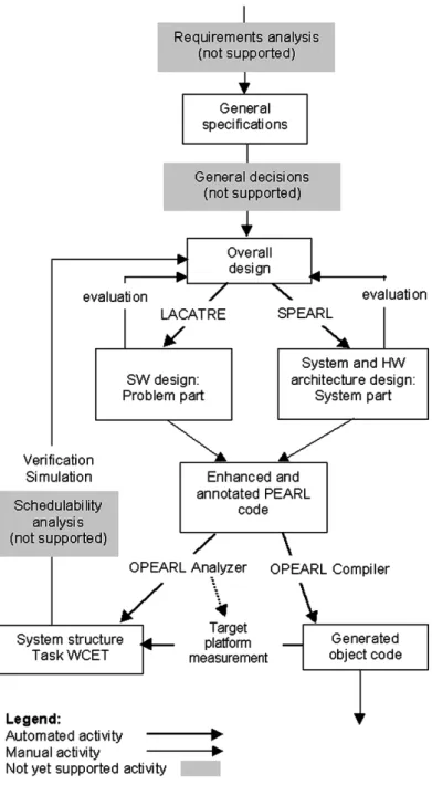
Development cycle of the application as pro-posed in this paper is shown in Figure 1. As already mentioned, for the time being, early stages of the development cycle like require-ments analysis are not supported. Also, to come to the first outline of the top-level over-all design, some preliminary decisions must be made, which can be re-considered and certainly refined during the design process.
The design can then start in parallel on both software and hardware architecture levels. Us-ing Specification PEARL (SPEARL) 7, 11]
basic description of hardware and system ar-chitecture is elaborated. The designer first sets up the coarse structure of the system as well as implementation parameters, which are then gradually detailed with time. When at least the outline of the hardware architecture is set up, software units (collections)may be associated
with it. To allow for that, during the develop-ment this model is detailed by information from LACATRE(e.g. number and basic structure of
tasks and other objects). Specification PEARL
enables early reasoning about the system inte-gration, but at the same time the hierarchical structure of the corresponding design tool also enables top-down stepwise refinement.
attributes. The LACATRE tool also performs structure and behaviour verification of the pro-gram model by checking whether the tasks are well formed and trying to avoid possible dead-locks and bottlenecks. In the early phases, prob-ably a lot of detailed algorithms will be replaced by placeholders and will be gradually more and more detailed during the forthcoming iterations. During that time, both processes can have im-pact on the overall design, thus allowing for op-timal implementation. Direct interference be-tween the LACATRE and SPEARL, however,
is not possible in this implementation, and will be subject of the forthcoming versions of the tools.
When the design on a certain level is complete, the system and the application descriptions are merged. As programs in standard PEARL con-sist of system and problem parts, the problem part of the PEARL program is a result of LA-CATRE and the system part is produced by SPEARL. The bold arrows represent that this activity is automated while, e.g., the evaluation is done manually.
The PEARL code is then input into the Ob-jectPEARL (OPEARL) compiler with a
built-in execution time analyser. In early phases only coarse design analysis is done in order to ob-tain a rough estimation of system’s structure and behaviour. During the design process, the estimation becomes gradually more precise and reliable until finally the object code for the tar-get platform can be generated.
At that stage already a good estimation of task’s execution times can be done, thus providing re-liable information for verification of system’s temporal behaviour. The pessimism necessarily involved is minimized by automated measure-ment of the pilot code generated by the analyser and supported by the background debugging mode facility of the employed microprocessor. Better option at this stage would be to perform a thorough schedulability analysis18]what we
find feasible, but is for the time being not sup-ported.
The estimated or measured temporal behaviour is checked against the specifications. It can also be simulated using the architectural model resulting from the system part, and the tasks’ behaviour described in the problem part. The cycle closes by returning to the overall design, which can be changed or refined according to the results of the validation.
3. Specification PEARL
Specification PEARL is a hardware/software
architecture specification and description lan-guage. It originates from PEARL for distributed systems 22]. The latter was defined to
sup-port the design of real-time systems and appli-cations, which often are of the distributed na-ture. They represent an extension to the Full PEARL 21] standards’ SYSTEM part, which
describes the hardware units being addressed in the PROBLEM part of the PEARL program. The description of the hardware architecture consists of the top-level “station layer” and the detailed-level “component layer”. There is a separate “program layer”, which depicts the software architecture.
Specification PEARL extends the standard PEARL for distributed systems in the manner consistently with the standard. Some constructs
have been added in order to enable the descrip-tion of asymmetrical distributed multiproces-sor systems and the peripherals, attached to the system. The parameters of the Specification PEARL components have been chosen based on the PEARL for distributed systems standard and our experience in designing an asymmetri-cal multiprocessor hardware platform 8] and
analysing the worst case execution times of PEARL programs. However, although moti-vated by the particular architecture, the method is universal enough to model a wide variety of different embedded systems.
Specification PEARL has two representations: the graphical and the textual one. They have an equivalent translation from the graphical to the textual form and vice versa. Both representa-tions are described in the sequel. The graphical symbols used to represent the components of Specification PEARL have been chosen in com-pliance with the philosophy of the LACATRE graphical constructs:
a common symbol for every component group, easy recognition and differentiation between different components,
specialised components are added additional graphical details in order to differentiate them from the other components in the group.
3.1. The Textual Specification PEARL
The textual system architecture description
12] consists of divisions, which describe the
components of the system architecture and their interconnections by looking at those from dif-ferent perspectives.
Station Division
In the station division, the processing nodes of the system are introduced, stating their most im-portant characteristics. Stations are treated as black boxes with connectors, called "PORTS",
by the other layers of the architecture descrip-tion. PORTs are a means of communication between the stations of a system and are ref-erenced by their program collection’s tasks. A similar concept is also used in UML20, 30].
station is associated with the state information, upon which it is being decided which applica-tion program collecapplica-tion is loaded and executed by the station.
Several types of stations have been defined. The default type is the BASIC station, which
repre-sents a general purpose processing node. To be able to describe asymmetrical architectures, two additional types of processing nodes have been defined: TASKPROCfor task processors and KER-NELPROCfor operating system kernel processors
8]. This comes from a widely accepted
con-cept of migrating the operating system functions to a separate processor, which enables better predictability of the actual program execution times.
To allow for the design of multiprocessor nodes, a “compound station” has been defined to be a set of stations, which are logically and/or
phys-ically strongly connected (they share the same
connections with other stations or peripheral de-vices). A multiprocessor node is introduced by
the PART OF attributes of the constituent
pro-cessing nodes.
Since in embedded systems design(intelligent)
peripheral devices are very important the PE-RIPHERAL station type was defined. The
at-tributes of peripheral stations differ from other stations’ attributes because of their large diver-sity. Hence, only a common denominator of their parameters is used. Their connections to the devices in the system are described by the attributes of their interface andPORTs(e.g.: the
direction of data flow, the protocol used and any additional signals which may be necessary for the communication). To support
schedulabil-ity analysis, every signal can be specified by its minimum inter-arrival time.
The basic components of a station are its pro-cessing elements, working stores and devices
(I/O, timers, etc). They are assigned
parame-ters, which are important for the execution time analysis during application program compila-tion and the parameterisacompila-tion of the RTOS and configuration manager.
Net Division
The topology of the system is described by port-to-port connections. In net division the physical port-to-port connections between the stations of
the system are listed giving their logical names and directions.
System Division
It represents an extended SYSTEM part, as obligatory in standard PEARL programs, which represents the programmer’s view of the system. System division encapsulates the hardware de-scription and the assignment of symbolic names to hardware devices. The described compo-nents from the station and net divisions are used.
Configuration Division
Configuration division describes the software architecture. The largest program component that is associated with a station and its state is a
COLLECTIONofMODULEs. It is possible to specify
under which conditions certain collections are removed from a station and which collections are loaded instead. These conditions are station state dependent.
Modules consist ofTASKs, which may
commu-nicate through PORTs. Tasks are described by
their trigger conditions and response times. Al-ternative implementations of tasks, which serve the purpose of increasing fault-tolerance and aid the feasibility of task scheduling, may be
defined(during scheduling a task with shorter
run time or longer response time can be sched-uled in order to maintain the feasibility of the schedule). The port-to-port connections
be-tween tasks are described by their directions and line attributes. Line attributes state which connections are always followed and which can be chosen from a preference list.
3.2. The Graphical Specification PEARL
The graphical equivalent 11] of the textual
ARCHITECTURE STATIONS
NAMES: KP
PROCTYPE: MC68307 AT 20 MHz
WORKSTORE: SIZE 65536 SPACE 0-'FFFF'B4 READ/WRITE WAITCYCLES 1
WORKSTORE: SIZE 32768 SPACE 0-'7FFF'B4 READONLY WAITCYCLES 1
INTERFACE: KP_IO (DRIVER: KPINOUT DIRECTION: INOUT SPEED: 20971520 BPS UNIT: FIXED) PORT KP_TP1_lin: INOUT FIXED
PORT KP_TP2_lin: INOUT FIXED STATEID: (NORMAL,CRITICAL) STATIONTYPE: KERNELPROC SCHEDULING: EDF
MAXTASKS: 20 MAXSEMA: 5 MAXEVENT: 15 MAXEVENTQ: 5 MAXSCHED: 30 TICK: 1E-3 SEC NAMES: Sensor1
STATEID: (NORMAL) STATIONTYPE: PERIPHERAL
INTERFACE: S1_IO (DRIVER: S1OUT DIRECTION: OUT SPEED: 20971520 BPS UNIT: BYTE) PORT S1: OUT BYTE
INTERMESSAGE PERIOD: 1E-3 SEC NAMES: Sensor2 ...
NAMES: TP1
PROCTYPE: MC68307 AT 20 MHz
WORKSTORE: SIZE 65536 SPACE 0-'FFFF'B4 READ/WRITE WAITCYCLES 1
INTERFACE: TP1_IO (DRIVER: TP1INOUT DIRECTION: INOUT SPEED: 20971520 BPS UNIT: FIXED) PORT TP1_KP_lin: INOUT FIXED
PORT TP1_S1: IN BYTE STATEID: (NORMAL) STATIONTYPE: TASKPROC SUPERVISOR: KP NAMES: TP2 ...
STAEND
NET
KP.KP_TP1_lin <-> TP1.TP1_KP_lin KP.KP_TP2_lin <-> TP2.TP2_KP_lin TP1.TP1_S1 <- Sensor1.S1 TP2.TP2_S2 <- Sensor2.S2 NETEND
SYSTEM NAMES: KP
KP.KP_TP1_lin INOUT KP.KP_TP2_lin INOUT NAMES: Sensor1
Sensor1.S1 OUT NAMES: Sensor2 ... NAMES: TP1
TP1.S1 IN
TP1.TP1_KP_lin INOUT NAMES: TP2 ...
SYSEND
CONFIGURATION COLLECTION KP_WS
PORTS KP_TP1_lin,KP_TP2_lin
CONNECT KP_WS.KP_TP1_lin INOUT TP1_WS.TP1_KP_lin VIA KP.KP_TP1_lin CONNECT KP_WS.KP_TP2_lin INOUT TP2_WS.TP2_KP_lin VIA KP.KP_TP2_lin
COLLECTION TP1_WS MODULES
TP1_WS_M1
EXPORTS (Actuator1) TASKS
Actuator1 (TRIGGER PORT S1,DEADLINE 100) PORTS S1,TP1_KP_lin
CONNECT TP1_WS.S1 IN VIA TP1.S1
CONNECT TP1_WS.TP1_KP_lin INOUT KP_WS.KP_TP1_lin VIA TP1.TP1_KP_lin
COLLECTION TP2_WS ... CONFEND
ARCHEND
1. Station layer: STATIONs andPERIPHERALs
with their interconnections,
2. Component layer:PROCTYPES,WORKSTORES
andDEVICESof aSTATIONwith their
inter-nal and global interconnections, and
3. Program layer: COLLECTIONs of MODULEs
and TASKs, which are associated with the
stations from the station layer.
3.3. Hardware Configuration Verification
The purpose of the hardware configuration ver-ification is to ensure a complete and coherent hardware architecture model with enough tim-ing information to enable integration verifica-tion with the program model.
There are three phases in the system model co-herence checking:
1. Completeness check: “Are all stations in the hardware architecture fully described?” is the main question to be answered here. It is not possible to reason about the sys-tem feasibility without these hardware ar-chitecture properties. It is also important to check that every component, which is referenced in the configuration, actually exists with its description.
2. Range and compatibility check: it is al-ways possible to make a mistake while inputting the values for the parameters. While some can only be detected by re-viewing the design by the designer, some mistakes like range errors, where the in-put data differs in the order of magnitude from the expected value range, can be de-tected automatically. It is also possible that we connect two stations through interface with different properties, which will surely result in a communication malfunction in case the configuration doesn’t change.
3. Software to hardware mapping check is the preparation to the integration verifica-tion and is described in the corresponding section.
3.4. Example Description of an Asymmetrical Architecture
To illustrate the expressive power and modelling capabilities of the Specification PEARL, the following example(Figure 2)is presented here.
An asymmetrical architecture is considered. It consists of two embedded task processors TP1 and TP2, which are supervised by a common kernel processor KP. They are receiving input from two peripheral devices Sensor1 and Sen-sor2 respectively. Their Actuator tasks are trig-gered by the signal from one or the other sensor. They are synchronised by the operating system being run by the KP station.
4. Software Design
4.1. LACATRE
LACATRE 31] is a language with graphical
and textual modes; it has been conceived as a contribution to the development of design tools for applications relying on multitasking. It cov-ers the end of preliminary design and detailed design of the software lifecycle and enhances the expression of the dynamic decomposition and task relationship. An application designed by means of graphical components of the LA-CATRE language is a 2-dimensional diagram made of LACATRE graphical objects (those
commonly involved in most of real-time ex-ecutives)and LACATRE connections(System
calls)which appear as graphical links between
the objects.
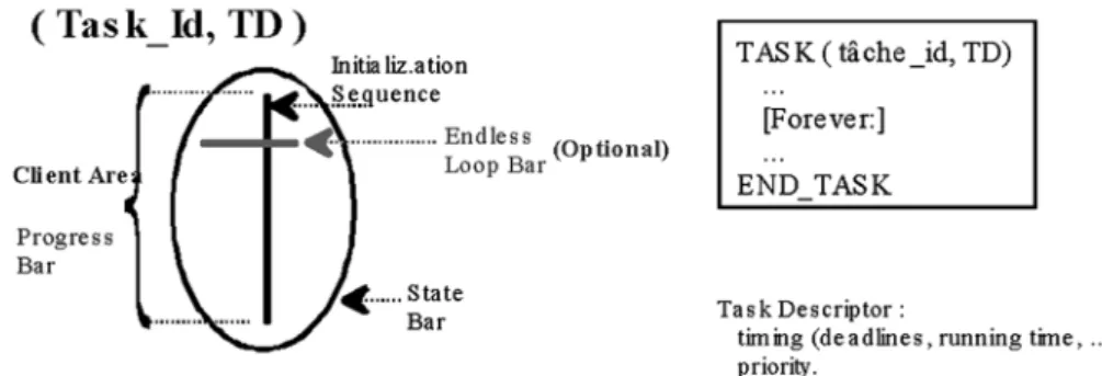
Fig. 3.Task Description.
LACATRE has two types of objects:
1. The programmable objects: the task, the interruption, the alarm, and the exception. These are the objects whose behaviour is user-defined.
2. The configurable objects: the semaphore, the mailbox, the message, the event, the resource, etc. These are the objects whose behaviour is completely defined by param-eter values set up during creation.
LACATRE Graphical symbols(Objects):
The graphical symbol of a LACATRE object is made of basic elements (lines) called areas
from which start and end linking symbols of LACATRE connections (system calls). There
are three types of areas:
1. State area: where LACATRE state system calls (creation) are anchored and which
may be applied to all LACATRE objects; 2. Progress area: specific to programmable
objects. It is an oriented line that describes the sequence of LACATRE system calls. It may be altered by means of LACATRE algorithmic forms(IF, WHILE,);
3. Action area: attached to a configurable ob-ject and has a specific name according to the concerned object.
Connections:
The LACATRE system calls are the ones used by the designer to express the interactions among objects. They are classified in 3 categories:
1. State system calls: allow for the modifi-cation of the state of an object: creation, deletion,
2. Action system calls: generate a communi-cation/synchronization relation between
programmable objects(mainly tasks)with
the help of configurable objects.
3. Progress system calls: provide straight synchronization between programmable ob-jects.
After the task design is finished, the building blocks of the textual representation thereof are assigned maximum execution times and input as task models into the program architecture of the Specification PEARL system model as TSTDs
(Timed State Transition diagrams,13], see
Sec-tion 6). The trigger conditions are converted
into start states, whereas the building blocks of the tasks are assigned working states. End states are produced for end-of-task, error and timeout conditions. The tasks in TSTD form are used later on in the integration verification.
4.2. Program Model Verification
The program model in LACATRE is translated to Shaw’s CRSM (Communicating Real-time
States Machines)internal representation in
or-der to perform the analysis of the designed tasks
15]. This enables the verification of:
structure(well formed tasks perform smoother
and safer and at the same time the basic build-ing blocks are identified, which can be as-signed maximum execution times to perform timing analysis)and
behaviour (possible deadlocks, bottlenecks,
5. Implementation and Analysis: ObjectPEARL
For the implementation of the application, object-oriented programming language ObjectPEARL is devised37, 38]. Like Specification PEARL,
it is based on programming language PEARL that was developed in late 60-ies by engineers from different real-time system domains. It has been refined during the years and its latest version(PEARL90) includes several elements
of modern programming languages, but is not object-oriented. It explicitly supports tasks and tasking operations, semaphores, signals, etc. However, for the consistent use in hard real-time systems, some restrictions must be applied. To allow for straightforward translation from object-oriented design tools and methodologies, traditional elements of real time systems are rep-resented by means of object-oriented notation. Thus, all elements of LACATRE and Specifi-cation PEARL notation can be translated into ObjectPEARL’s code.
5.1. Object-oriented Extension of PEARL
For introduction of classes, similar approach as in C++ was used. In both cases, a class is
defined as an extension to the structure. Be-cause of simplicity of code generation and ex-ecution time analysis, it was decided not to use multiple inheritances of classes. Therefore, a class can be descendent of only one parent class. All traditional elements of classes were included(i.e. variables, methods, constructors
and destructors). Like other object-oriented
languages, ObjectPEARL also supports poly-morphism through virtual methods.
In addition, a special type of variables called virtual variables or properties was introduced. Properties behave as ordinary variables with two additional methods. The first method is used for reading the variable and the second is used to change its value. Properties operate in similar manner as those used in the COM automation model29].
There are also special kinds of properties that are declared only for specification purposes and no code is associated with them. They can rep-resent certain non-program-specific attributes.
For example, attributes that represent param-eters of graphical appearance of an object in LACATRE or non-programmatic attributes of Specification PEARL can be given in this way. This allows two-way translation between tex-tual and graphical representation of the applica-tion. As an ultimate goal, no additional editor or tool for coding should be necessary to develop an application.
5.2. Object-oriented Representation of Tra-ditional Elements of Real-Time Appli-cations
To exploit the advantages of object-oriented ap-proach, traditional elements of real-time sys-tems are also represented as classes and objects. To provide for this, a way to represent tasks, semaphores, bolts, signals etc. was studied.
Tasks in PEARL and some other traditional pro-gramming languages are considered as a special kind of procedures, which can be executed in parallel under control of the operating system. For this purpose, a set of well-defined tasking operations is defined.
On the other side, objects are traditionally con-sidered as extensions to the static data types. Objects do not have direct control over their execution and there is usually no provision for tasking.
Both views can be combined if task is consid-ered as an object with a method that represents the main task behaviour and with several meth-ods for tasking. Similar approach is used in Java.
General task in ObjectPEARL is declared as shown in Figure 4.
Data types likeTASKCONTEXTandTASKSTATEare system-defined classes that represent context of the task, its current state, etc. VariableFContext
and methods SaveContex and RestoreContex
TYPE
TASK CLASS PRIVATE
FContext TASKCONTEXT
SaveContex PROCEDURE(ProcContext REF TASKCONTEXT) RestoreContext PROCEDURE(ProcContext REF TASKCONTEXT) SetState PROCEDURE(Value TASKSTATE)
GetState PROCEDURE RETURNS(TASKSTATE) ...
PROTECTED
MainProc PROCEDURE VIRTUAL ABSTRACT MAIN PUBLIC
Activate PROCEDURE (Schedule SCHEDULE, Deadline DURATION) VIRTUAL Terminate PROC VIRTUAL
Suspend PROC VIRTUAL ...
PROPERTY State TASKSTATE READ GetState WRITE SetState PROPERTY CurrSchedule SCHEDULE READ GetCurrSchedule PROPERTY Deadline DURATION READ GetDeadline
... ]
Fig. 4.Declaration of a Task in ObjectPEARL.
execution method. Tasking operations are de-clared as public to allow the access from outside of the object.
Similar to this, other elements of real time sys-tems can be represented as classes. For exam-ple, a semaphore can be declared as in Figure 5.
TYPE
SEMA CLASS PRIVATE
FCount FIXED
FSemaState SEMASTATE PUBLIC
Preset CONSTRUCTOR(InitCount FIXED) Request PROC(TimeOut DURATION) Release PROC
Try PROC RETURNS(BIT(1)) ]
Fig. 5.Declaration of a Semaphore.
Like in tasks, private variablesFCountand FSe-maStateare used for internal implementation of
a semaphore. Again, private variables and im-plementation of methods is under direct control of the operating system. Because of the need for temporal predictability of the programs in ObjectPEARL, there is an additional parame-ter associated with Request method that serves as deadline on waiting for the semaphore to be released.
Benefits of object-oriented description can be fully utilised when there is already a wide set of predefined data types(classes)and when
com-ponents are divided into specialised groups(e.g.
periodic and a-periodic tasks).
5.3. Compiler for ObjectPEARL With Inte-grated Execution Time Analyser
Parallel to the programming language design, a compiler was implemented. The goal was to de-velop a modular and flexible compiler that could be easily modified based on results of theoret-ical research of the development environment. Compiler should be also target-system indepen-dent although in its current version it generates code only for one processor. Nevertheless, com-piler should generate efficient code, thus several optimization techniques were included into the compiler.
One of the most important issues in implemen-tation of the compiler/analyser was realistic
es-timation of worst-case execution times of tasks, which is the basis for timing analysis on higher levels. Too pessimistic execution times of tasks could declare a system unfeasible and require unnecessary effort to improve it. On the other hand, too optimistic estimations cause deadline misses when an application is executed on a real system. Worst-case execution time analy-sis can also be done on the specifications or on the program code but most accurate results can be achieved by execution analysis of compiled code or by direct measurement of the program on the target.
uses simple recursive descent parsing algorithm with semantic routines for code generation and temporal analysis. In its current version, it generates code for Motorola’s ColdFire micro-controller.
Translation of ObjectPEARL code into the stan-dard PEARL was also studied but there were several semantic discrepancies between both languages(e.g. visibility of the class members).
These differences cannot be easily considered by using simple translation techniques.
5.4. Translation Process and Execution Time Analysis
Standard PEARL programs are divided into two parts: system and problem part. In the system part hardware specific peculiarities are defined, e.g. input/output devices, communication
de-vices etc. System part can be generated directly from the Specification PEARL. There are other attributes in Specification PEARL that are not directly used in code generation but they can be used to improve validation process of the appli-cation. For example, in Specification PEARL there is a specification of available memory for the program code. Compiler can easily check if the compiled code is larger than the speci-fied storage room. Other attributes can be used during execution time analysis(e.g. processor
speed, memory wait states, etc.).
In the problem part algorithmic elements of the application are presented independently of the hardware. Problem part can be directly gen-erated from LACATRE notation. By using ob-ject representation of all real time elements, this translation can be simple and straightforward. Worst-case execution time analysis is performed in two phases. In the first phase, structure of the program by means of blocks, loops, decisions, etc., is identified. Then for all linear parts of the code maximal execution time is estimated. Similar to the code generation, execution time analysis is highly dependent on the micropro-cessor used. Because of this, basic execution time analysis should be integrated within a low-level code generator. Thus, in ObjectPEARL compiler each object for code generation also has a corresponding method for execution time estimation. High-level temporal analysis is
per-formed on the structure of the program using simple recursive rules36].
Because of different mechanisms of modern mi-croprocessors to improve overall performances
(i.e. cache, pipeline, etc.), the estimated
exe-cution times based only on compiled code can be too optimistic. Execution times available for individual instructions are given for the ideal sit-uation where instruction is already in the cache and no stall in pipeline or collision on address and data busses are considered. Although we tried to improve algorithm for execution time calculations, result was not always acceptable. For that reason it was decided to implement di-rect measurement of execution times of sequen-tial parts of code on the target processor. In this sense, the debug module of the target proces-sor was utilized, featuring background run-time debug support. With this module, it is possi-ble(over a separate external bus)to stop or run
a program on the processor, read or write into the registers and memory, set breakpoints, etc. This allows to load the compiled code into the processor’s memory, run segments of code and measure the elapsed time.
The results of the execution time analysis are es-timated execution times of tasks. These results with some additional information (e.g.
dead-lines of tasks, activation conditions, etc.)
pro-vide the data for further schedulability analysis. Idiosyncrasy of the microprocessors is a funda-mental impediment in accurate execution time estimation. Because of that, generality of the approach is limited: the timing analysis has to be adapted for every new processor. However, by becoming widely used, BDM to some ex-tend standardises the measurement of execution times at least within the Motorola family of mi-croprocessors.
6. Verification of the Integral Design by Co-Simulation
According to25], for most applications running
in real-time their computational model can be expressed in the form of the following “equa-tion”:
The TASKs of the system represent the basic program units whose main properties are their trigger conditions and timing limitations as well as being part of a MODULE and COLLEC-TION. This information is sufficient to build a rough program model, but it is not enough to determine the feasibility of the program con-figuration on the model of the target system. Therefore, they have been extended by timed state transition diagrams, which represent the dynamic behaviour of tasks, whereas their ex-ecution can be simulated on the model of the target system.
Timed State Transition Diagrams (TSTD) act
as timed finite state automata and consist of: start states(task trigger conditions),
transient states(working states)and
final states(finalisation actions).
The connections between states represent the applications’ progress in time. All connections are local(i.e.: bound to the states of one task).
Inter-task co-operation is modelled by the state actions-system calls of the operating system. These also enable the fulfilment and checking of continuation preconditions of states. The op-erating system is invisible to the user except for its system calls and configuration, which is set-up by setting the parameters of the KERNEL station.
Every state contains the following data: state type(start, working or final state),
precondition for the states’ execution(trigger
condition for a start state),
timeout condition(shortest and maximum
ex-ecution times),
timeout action(the state where the execution
is diverted in case the timeout occurs),
connection to the next state in case the exe-cution continues successfully,
activities, which are carried out within the execution of this state(PEARL-comment or
system call).
System calls, which trigger specific task states, make resource requests and change the state of the system. Interfaces and ports are referenced in communication system calls as configured in the hardware/software architecture.
The activities within a state are a set of actions, which are carried out while the task is in the state. It is foreseen that the actions may be either a system call and/or a mini-specification
(PEARL comment). Their execution time is
es-timated by the designer and used while setting the time-out interval for the state.
Verification Method
After the coherence of the design has been checked, the feasibility of the modelled sys-tem is validated. It has been established that co-simulation of the execution of the tasks on the specified (hardware and software) system
architecture is the most appropriate verification method for our methodology.
The program as well as hardware models may be modified if necessary due to the feasibility es-timation from the co- simulation or subsequent execution time analysis that may differ from the execution time estimates in the program model. The method of the next critical moment co-simulation of execution with time boundaries has been chosen as the method for verification of the designs. The boundary time values are considered along with the variables’ values, as it is usual in the program verification practice. For each state the shortest and the longest trans-action times are checked.
By taking the shortest and the longest transac-tion times through the task states of the system, the time domain is sufficiently covered to be able to generalise the results of arbitrary trans-action time of every state and herewith also the system as a whole.
The following concept of correctness for the described method of verification has been de-fined: “The system fails in the case when during co-simulation the system reaches an undefined state or its predefined time frame is violated and no timeout-action is defined.”
7. Conclusion
The pragmatic combination of the tools pre-sented in this paper enables parallel design of the hardware and the software parts and of-fers textual as well as graphical notations for both domains. It allows for early mapping of the problems onto the appropriate hardware or software solutions and their design. Further, early verification and validation of functional and timing properties is enabled considering be-haviour of hardware and software components of the application.
By taking already existing tools, problems were anticipated from the beginning. The main weak points of the tools in the combined approach include:
lack of the means for requirements engineer-ing of the system,
lack of the possibility of direct mutual im-pact of the solutions between LACATRE and SPEARL,
PEARL does not explicitly support certain useful LACATRE constructs(e.g. mailboxes),
in the current version of LACATRE it is not possible to change the graphical model by modifying the textual form of the application, LACATRE does not allow for hierarchical top-down design of larger applications, it does not itself explicitly deal with tempo-ral properties and does not support deadline-driven scheduling.
Most of the listed problems could be solved by applying certain changes in the forthcoming versions of LACATRE, SPEARL and OPEARL. Apart of that, for the successful use of the methodology an integrating environment should be developed.
References
1] G. AGHA, The Structure and Semantics of Actor Languages, in J.W. de Bakker, W.P. de Roever, and G. Rozenberg, editors,Foundations of Object-Oriented Languages, pp 1–59, Springer Verlag, 1991.
2] F. BALARIN, M. CHIODO, P. GIUSTO, H. HSIEH, A. JURECSKA, L. LAVAGNO, C. PASSERONE, A.
SANGIOVANNI-VINCENTELLI, E. SENTOVICH, K.
SUZUKI, B. TABARRA, Hardware-Software Co-Design of Embedded Systems: The POLIS Ap-proach,Kluwer Academic Publishers, 1997.
3] G. BOOCH, I. JACOBSON, J. RUMBAUGH ET.AL.,The
Unified Modeling Language for Object-Oriented Development Version 1.0, UML Notation Guide, UML Summary, UML Semantics; Rational Soft-ware Corporation, January 1997 and the UML 1.1 update of Sept. 1997.
4] G. BORRIELLO, P. CHOU, ROSSB. ORTEGA, Embed-ded System Co-Design: Towards Portability and Rapid Integration,Hardware/Software Co-Design, pages 243–264, Kluwer Academic Publishers, 1996.
5] A. BURNS, A. J. WELLINGS, HRT-HOOD: A Struc-tured Design Method for HRTS,Real-Time Systems, Vol. 6, pp. 74–114,1994.
6] Z. CHAOCHEN, JI WANG, A. P. RAWN, A Formal Description of Hybrid Systems,Hybrid Systems III, eds. R. Alur and T. Henzinger & E. Sontag, LNCS 1066, Springer-Verlag, 1996.
7] M. COLNARICˇ, D. VERBER, W. A. HALANG, A Real-Time Programming Language as a Means of Expressing Specifications, Proceedings of 21st IFAC/IFIP Workshop on Real-Time Programming (WRTP’96), Gramado, RS, Brazil, November 1996.
8] M. COLNARICˇ, D. VERBER, R. GUMZEJ, W. A. HA
-LANG, Implementation of Real-Time Embedded Control Systems,Real-Time Systems, Kluwer Aca-demic Publishers, May 1998.
9] C. DIETZ, Action Diagrams, Proceedings of 22nd
IFAC/IFIP Workshop on Real-Time Programming (WRTP’97) (Preprints), September 15–17, 1997, Lyon, France.
10] T. J. ERIKSEN, S. T. HEILMANN, M. HOLDGAARD, A. P. RAVN, Hybrid Systems: A Real-Time
Inter-face to Control Engineering, Proceedings of 8th Euromicro Workshop on Real-Time Systems, IEEE, pp. 114–120, 1996.
11] R. GUMZEJ, M. COLNARICˇ, J. P. BABAU, J. SKU
-BICH, Hardware Architecture Components for
Real-Time Systems Design, in Proceedings of the 7th Electrotechnical and Computer Science Conference ERK’98, Vol. A pp. 41–44, Portoroz, Slovenia, September 1998.
12] R. GUMZEJ, M. COLNARICˇ, D. VERBER ANDW. A. HALANG, Towards standard-based specification and
design of embedded real-time systems, in Proceed-ings of Euromicro’98, V¨aasteras, Sweden, August˚
25–27, 1998.
13] R. GUMZEJ, M. COLNARICˇ, An approach to real-time systems co-design and verificaiton, inProceedings of the IASTED international conference on Control and Applications, Cancun, Mexico, May 2000.
14] R. GUPTA,Co-Synthesis of Hardware and Software
15] Z. HUANG, A. LEGAIT, M. MARANZANA, E. NIEL, J. J. SCHWARZ, J. SKUBICH, Techniques for the
Behaviour Verification of Real-Time Multitasking Components,14th IFAC World Congress, 5–9 July 1999, pp. 6, Beijing, Chine.
16] International standard ISO/IEC 9126: Information
technology — Software product evaluation — Qual-ity characteristics and guidelines for their use,First edition 1991-12-15, Reference number ISO 9126 : 1991.
17] International standard ISO/IEC 9127:
Informa-tion processing systems — User documentaInforma-tion and cover information for consumer software packages,
First edition 1988-09-01, Reference number ISO 9127 : 1988(E).
18] E. KLIGERMAN, A. D. STOYENKO, Real-Time Eu-clid: A Language for Reliable Real-Time Systems,
IEEE Transactions on Software Engineering, Vol. 12, No. 9, September 1986, pp. 941–949.
19] I. LEE, S. DAVIDSON, R. GERBER, Communicat-ing Shared Resources: A Paradigm for IntegratCommunicat-ing Real-Time Specification and Implementation, Foun-dations of Real-Time Computing: Formal Specifi -cations and Methods, Kluwer Academic Publishers, 1991.
20] A. LYONS, UML for Real-Time Overview, Objec-Time Limited, April 1998.
21] Full PEARL,DIN 66253, Part 2.
22] Distributed system PEARL,DIN 66253, Part 3.
23] H. DEMAN, I. BOLSENS, B. LIN, K. VANROMPAEY, S. VERCAUTEREN & D. VERKEST, Co-Design of
DSP Systems, Hardware/Software Co-Design, pages 75–104, Kluwer Academic Publishers, 1996.
24] V. J. MOONEYIII, Hardware/Software Co-Design
of Run-Time Sytems,School of Electrical and Com-puter Engineering, Georgia, PhD thesis, Sep. 1998.
25] A. K. MOK, Towards Mechanization of Real-Time System Design,Foundations of Real-Time Comput-ing: Formal Specifications and Methods, Kluwer Academic Publishers, 1991.
26] L. MOTUS, T. NAKS, Formal timing analysis of OMT designs using LIMITS,Computer System Science and Engineering, Vol. 13, No. 3, pp. 161–170, 1998.
27] ObjecTime Limited,ObjecTime Overview,1994.
28] J. S. OSTROFF, A Visual Toolset for the Design Of Real-Time Discrete Event Systems,IEEE Transac-tions On Control Systems Technology, May 1997.
29] D. ROGERSON,Inside COM,Microsoft Press, 1997.
30] J. RUMBAUGH, B. SELIC, Using UML for
Model-ing Complex Real-Time Systems,Rational Software Corporation, ObjecTime Limited, March 1998.
31] J. J. SCHWARZ, J. J. SKUBICH, Graphical program-ming for Real-Time Systems,Control Engineering Practice, Vol. 1, No. 1, pp. 43–49, 1993.
32] A. C. SHAW, Communicating real-time state ma-chines,IEEE Trans. Software Engineering, Vol. 18, No. 9, pp. 805–816.
33] S. SHLAER, S. MELLOR, Object-oriented systems
analysis: modelling the world in data, Prentice Hall, Englewood Cliffs, NF, 1998.
34] TRAORE I., SAHRAOUIABD-EL-KADER, A Multi-formalism Specification Framework with State-charts and VDM,Proceedings of 22nd IFAC/IFIP Workshop on Real-Time Programming (WRTP’97)
(Preprints), September 15–17, 1997. Lyon, France.
35] OMG Unified Modeling Language Specification (draft), Version 1.3, March 1999.
36] D. VERBER, Programming and timing analysis of
hard real-time systems, Master thesis, 1997, Uni-versity of Maribor
37] D. VERBER,Object Orientation in Hard Real-Time
System Development, Doctoral thesis, 1999, Uni-versity of Maribor, Slovenia.
38] D. VERBER, M. COLNARICˇ,Object Oriented
Exten-sion to Development of Hard Real-Time Systems,to appear on SCI/ISAS 2000, Orlando, Florida.
Received:April, 2000
Revised:June, 2000
Accepted:July, 2000
Contact address:
Roman Gumzej University of Maribor, Faculty of Electrical Engineering and Computer science,
Smetanova 17 2000 Maribor Slovenia e-mail:[email protected]
Jean-Philippe Babau INSA de Lyon+
Bat 502 - L3i 20 Av A. Einstein 69621 Lyon, France e-mail:[email protected]
ROMANGUMZEJjoined the Faculty of Electrical Engineering and Com-puter Science at the University of Maribor, Slovenia, in 1994, as a junior research follow. He received his Master of Science and Doctor of Sci-ence degrees in 1997 and 1999 respectively. He is currently a teaching assistant and research engineer at the same faculty.
His main research interests are real-time systems, their co-design, op-erating systems as well as verification and validation. He is a member of the IEEE Computer Society.
DOMENVERBERis assistant professor at the Faculty of Electrical En-gineering and Computer Science, University of Maribor, Slovenia. He received his Master of Science and Doctor of Science degrees in 1996 and 1999 respectively.
MATJAZˇ COLNARICˇ is associate professor at the Faculty of Electrical Engineering and Computer Science, University of Maribor, Slovenia, from which he also received his Master of Science and Doctor of Sci-ence degrees in 1983 and 1992, respectively. He chairs the Real-Time Systems Laboratory and teaches courses on microprocessors, real-time systems, and algorithms and data structures.
His main research interests are related to embedded real-time control systems, their hardware and system architectures, operating systems, programming languages as well as application design techniques and methodologies therefor.
Dr. Colnaric has authored, or co-authored, some 80 journal and confer-ˇ
ence papers and book chapters, mainly in the real-time area. He served in programming committees of a number of international conferences, he organised special sessions and chaired them. He is a member of the IEEE Computer Society and its TCs on Real-Time Systems and Complexity in Computing. He is also a member of IFAC Technical Committee on Real-Time Software Engineering.
JEAN-PHILIPPEBABAU is an assistant professor in the department of computer science at the INSA(engineer school)of Lyon. He received
his PhD in computer science from the University of Poitiers in 1996. His research interests include the design, object-oriented techniques, and the analysis of temporal behavior for complex real-time systems.