BANDWIDTH ENHANCEMENT IN MICROSTRIP PATCH
ANTENNA
USING LEFT-HANDED METAMATERIAL
STRUCTURE AT MULTIPLE OPERATING FREQUENCY
Gourav Singh Rajput*ABSTRACT
The metamaterial substrate has a potential to reduce the circuit size of the antenna as
well as maintain the amplitude of the return loss at the specific resonant frequency. The
most attractive feature of the substrate is the ability of enhancing the bandwidth of a
patch antenna. Metamaterial structures that provide electromagnetic properties not found
in naturally occurring media; properties such as negative index of refraction, negative
permeability or negative permittivity. Microstrip patch has some drawbacks such as
restricted bandwidth, low gain and a potential decrease in radiation pattern. For removal
of the drawback of patch antenna, Metamaterial structure is designed on the patch
antenna at the height of 3.2 mm from the ground plane. by using CST(computer
simulation technology software) MICROWAVE STUDIO.
In this paper, the proposed Rectangular microstrip patch antenna is used for improving
the potential parameters like Bandwidth, Return Loss, Gain, and Directivity. This antenna
is small size, cheap, compact and easy to fabricate, and achieve good
radiation characteristics with higher return loss. This antenna can have wide application
in a great variety of wireless communication. Double-Negative properties of the proposed
metamaterial structure have also been verified by using Nicolson-Ross-Weir Method
(NRW).The S-parameters from the computer simulation technology (CST) are proven the
negative permittivity. This metamaterial antenna has high potential in the future
telecommunication industries in enhancing the performance of the technology for
consumers.
This proposed design is oprated at different frequencies like 1.824 GHz, 2.088 GHz,
2.724 GHz, 2.85 GHz, and 1.026 GHz.
Keywords: Recangular Microstrip Patch Antenna (RMPA), Left Handed
Metematerials, Return Loss, Directivity, Impedance Bandwidth.
I. INTRODUCTION
An antenna is defined as a part of a transmitting or receiving system which is designed
to radiate or to receive electromagnetic waves [1]. Patch antennas have attractive
properties including the low profile, light weight, compact and conformable in structure,
and easy to be integrated with solid-state devices [2]. Application of a conventional
antenna always limited since they are governed by the ‘right hand rule’ which determine
how electromagnetic wave should behave. However, a metamaterial substrate offers an
alternative solution to a wider antenna applications using the ‘left hand rule’ [3].
Metamaterials are composite materials with unique electromagnetic properties due to the
interaction of electromagnetic waves with the finest scale periodicity of conventional
materials [4]. The person who is responsible in discovering the concept of metamaterials
is Veselago in 1967 [4]. He assumes an unknown material that has a negative
permeability and permittivity in the same frequency range and it shows the abnormal of
electromagnetic properties when the uniform plane-wave propagation [4-6] was studied.
As a result, the left-handed material (LHM) has a reverse basic feature of light, such as
negative refractive index (NRI) [5-6]. Surprisingly, the idea got only little attention until
came to the year 2000 when Smith further studied the LHM and realized this material was
a periodically-arranged conducting concrete and also shows extraordinary properties [6].
The first structure that used to prove the existing of metamaterial was a split ring structure
that invented in the year 2001 by Shelby Smith and Schultz from the University of
California [7]. After that, another three new structures were proposed in the year 2005,
starting with the symmetrical ring structure than omega structure and the latest one was S
structure [8]. There are several methods to verify the permittivity and permeability of a
substrate can be analyzed from S-parameters. A concentration on the application of the
metamaterial in designing a patch antenna in order to enhance the performance as well as
to realize it in a small size will be investigated using Computer Simulation Technology
(CST) Microwave Studio. The properties of the metamaterial structure and
characteristics of the rectangular patch antenna were also investigated. The most four
popular methods are Nicolson-Ross-Weir (NRW), NIST iterative, new non-iterative and
short circuit techniques [9]. All methods are based on the S- parameters that obtained
from the simulation or measurement results.
In modern wireless communication systems, the microstrip patch antennas are commonly
important issue in reducing the volume of entire communication system. The important
parameters of any type antenna are impedance bandwidth and return loss. The impedance
bandwidth depends on parameters related to the patch antenna element itself and feed
used.
II. DESIGN SPECIFICATIONS
The RMPA parameters are calculated from the following formulas. Desired Parametric Analysis [8] [9]
Calculation of Width (W):
(1)
Where
C = free space velocity of light, Ɛ r =Dielectric constant of substrate
The effective dielectric constant of the rectangular microstrip patch antenna:
(2)
Actual length of the patch (L):
(3)
Calculation of length extension
:
(4)
III. ANALYSIS OF RECTANGULAR MICROSTRIP PATCH ANTENNA
AND METAMATERIAL STRUCTURE WITH SIMULATED RESULTS.
The parameters of rectangular microstrip patch antenna are calculated first mathematicallythen simulated in software laboratory. The physical parameters of rectangular microstrip patch
antenna are W= 46.07 mm, L= 35.85 mm, length of transmission line feed= 35.57 mm, with
width of the feed= 5 mm. The rectangular microtrip patch antenna designed on one side of
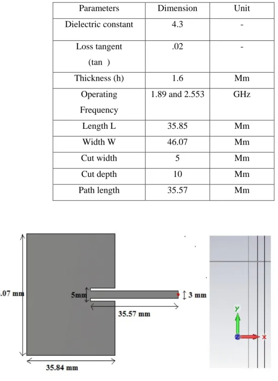
The parameters of RMPA alone are mention in the Table
Fig 1: Rectangular microstrip patch antenna (RMPA) designed at multiple frequency.
The Rectangular microstrip patch antenna is designed by using CST-MWS (computer
simulation Technology) software with 1.6 mm height from the ground plane. Parameters Dimension Unit
Dielectric constant 4.3 -
Loss tangent
(tan )
.02 -
Thickness (h) 1.6 Mm
Operating
Frequency
1.89 and 2.553 GHz
Length L 35.85 Mm
Width W 46.07 Mm
Cut width 5 Mm
Cut depth 10 Mm
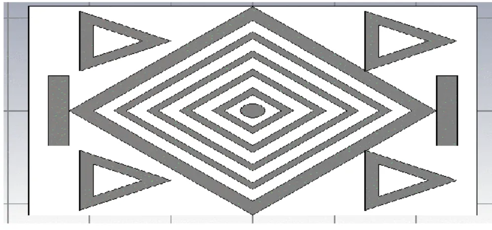
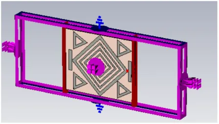
Fig 2. Design of desired metamaterial structure at the height of 3.2 mm from ground plane.
In the above figure 3 and figure 3, proposed microstrip patch antenna design has the better response
as parameters like Impedance Bandwidth, Return loss and Directivity at operating frequency in
comparison to RMPA alone. The Metamaterial design is a combination of triangular shapes,
rectangular shapes and strip lines on substrate material centered at origin. This design is easy to
fabricate, cheap, small size and removed the drawback of Rectangular microstrip patch antenna at
different operating frequency.
Fig 2. Simulation result of RMPA alone.
The above figure shows that Bandwidth and Return loss of Rectangular microstrip patch
antenna (RMPA) are 10.1 MHz and -10.276 dB respectively.
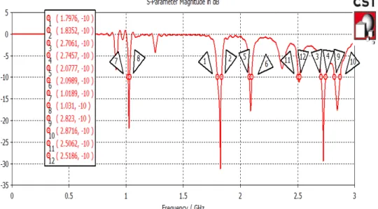
Fig 5. Simulation results of RMPA with desired metematerial structure at multiple operating
Bandwidth and Return loss of RMPA alone is 10.1 MHz and -10.276 dB at operating
frequency respectively. By using metamaterial, the proposed antenna has bandwidth as12.4
MHz, 48.6 MHz, 12.1 MHz, 21.2 MHz, 39.6 MHz and 37.6 MHz at different operating
frequency in comparison to RMPA. Return loss of RMPA using metamaterial is reduced up to
-21.9 dB,-31.204 dB,-17.8 dB, -29.29 dB and-17.98 dB in comparison to RMPA.
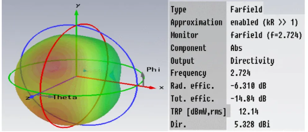
Fig 6. Radiation pattern of RMPA showing directivity of 5.328 dBi.
Fig 7. Radiation pattern of desired antenna showing Directivity of 6.225 dBi.
The above figure shows that the directivity of rectangular microstrip patch antenna (RMPA)
alone is 5.328 dBi at 2.724 GHz. When as compared to RMPA alone, the Directivity of desired
antenna is increased from 5.328 dBi to 6.225 dBi at 2.724 GHz.
Nicolson-Ross-Weir Method (NRW):
One methodology that makes use of the scattering parameters S11 and S21 to calculate the
mentioned complex parameters of samples is named Nicolson-Ross-Weir (NRW) (Nicolson and
calculation of complex permittivity and permeability of materials. The obtained S- parameters are
then exported to Microsoft Excel Software for calculating the value of the permittivity and
permeability of the proposed design, using the Nicolson-Ross-Weir (NRW) approach.
The proposed structure is placed between the two waveguide ports [12][13] at the left & right of the
X-Axis in order to calculate the S11 and S21 parameters so as to prove that the proposed
structure possesses Double Negative metamaterial properties. In figure 4, Y-Plane was defined as
Perfect Electric Boundary (PEB) and Z-Plane was defined as the Perfect Magnetic Boundary
(PMB). Subsequently, the wave was excited from the negative X-axis (Port 1) towards the positive
X-axis (Port 2).
Figure 4: Proposed metamaterial Structure placed between the two Waveguide Ports
at the left & right of the X-Axis.
Equations used for Calculating Permittivity & Permeability using Modified
NRW Approach [6]-[8]
Where,
V2 = S21 - S11
ω = Frequency in Radian
d = Thickness of the Substrate
c = Speed of Light
V2 = Voltage Minima
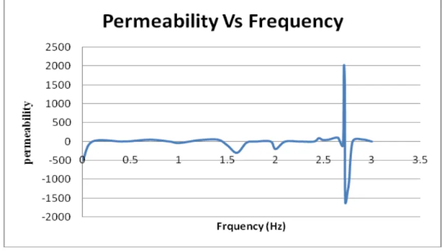
Figure 5: Permittivity versus Frequency Graph obtained from Microsoft Excel Software
In above figure, Permeability and Permittivity of left handed material or Metamaterial is -1650
H/ m, and -2100 F/ m at 2.724 GHz respectively. According to ‘Pendry’ the metamaterial
structure is conventionally composed of split ring resonator and thin wire or strip line
which provides negative Permittivity and Permeability. It is clear that material is a Double
Negative Materials (DNG, i.e.
ε
< 0 andµ
<0). It is also called the left handed Metamaterial because Left-handed meta-material name was given because the electric field, magnetic fieldand the wave vector formed a left-handed system.
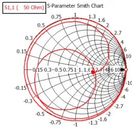
Figure 14. Smith chart of simple Rectangular microstrip patch antenna.
Figure 15. Smith chart of RMPA loaded with metamaterial.
The Smith chart can be used to simultaneously display multiple parameters
including impedances, admittances, reflection coefficients, scattering parameters, noise figure
circles, constant gain contours and regions for unconditional stability, including mechanical
vibrations analysis. The Smith chart is most frequently used at or within the unity
frequency. The circle cuts the resistive part at 2.22 on x axis for RMPA alone and cuts
resistive parts at .72 , 1.05, .155,.226,2.758, on x axis for proposed antenna, which is
normalized at 50 ohm for perfect matching. The real utility of the Smith chart, it can be used to
convert from reflection coefficients to normalized impedances (or admittances), and vice versa.
From above smith chart, it is clear that proposed antenna operates at different operating
frequency.
IV. SIMULATION RESULTS
There are several important antenna characteristics that should be considered when choosing
an antenna for fabrication as follows narrow bandwidth, higher return loss, low efficiency, low
gain, low power handling capacity, excitation of surface wave. Bandwidth and return loss of
Rectangular microstrip patch antenna (RMPA) is 10.1 MHz and -10.276 dB at operating
frequency respectively. Bandwidth of proposed antenna is increased up to 48.6 MHz, 39.6
MHz and 37.6 MHz in comparison to patch antenna at multiple operating frequency. Return
loss of proposed antenna is reduced up -21.9 dB,-31.204 dB, and -29.29 dB at multiple
operating frequency.
V. CONCLUSION
The simulated results provide bandwidth and directivity improvement, which encourages
fabricating the structure. On making some variations in antenna parameter gain can be
improved up to desired limit but some practical limitation should be taken care while
fabricating the structure on CST- MWS software. The drawback of Patch Antenna was p o o r
impedance bandwidth. For this purpose, Rectangular microstrip patch antenna loaded with
metamaterial structure has been proposed for improving the bandwidth by using CST
MICROWAVE STUDIO in this paper.
ACKNOWLEDGMENT
The authors wish to thank their parents for their constant motivation without which this work
would have never been completed. The authors are grateful to the Dr. Sanjeev Jain Director
MITS Gwalior for providing us lab facilities to complete this project work. We also express our
gratitude towards Dr. Sarita S Bhadoria Professor, HOD Dept. of Elex MITS for their
REFERENCES
[1] "IEEE standard definitions of terms for antennas," IEEE Std 145-1983, 1983.
[2] Y. P. Zhang and J. J. Wang, "Theory and analysis of differentially-driven
microstrip antennas," IEEE Transactions on Antennas and Propagation, vol. 54, pp.
1092-1099, 2006.
[3] A. Semichaevsky and A. Akyurtlu, "Homogenization of metamaterial-loaded substrates
and superstrates for antennas," Progress In Electromagnetics Research, vol. 71, pp. 129-147,
2007.
[4] M. Lapine and S. Tretyakov, "Contemporary notes on metamaterials," Microwaves,
Antennas & Propagation, IET, vol. 1, pp. 3-11, 2007.
[5] E. Nader a n d R . W. Ziolkowski, "A positive future for double negative metamaterials,"
Microwave Theory and Techniques, IEEE Transactions, vol. 53, pp. 1535-1556, 2005.
[6] L. Le-wei, Y. Hai-ying, W. Qun, and C. Zhi-ning, "Broad-bandwidth and low-
loss metamaterials: theory, design and realization," Journal of Zhejiang University
SCIENCE A, vol. 7, pp. 5-23, 2006.
[7] B. Szentpali, "Metamaterials: a new concept in the microwave technique,"
in Telecommunications in Modern Satellite, Cable and Broadcasting Service, 2003.
TELSIKS 2003. 6th International Conference, pp. 127-132 vol.1, 2003
[8] L. Ran, J. Huangfu, H. Chen, X. Zhang, K. Cheng, T. M. Grzegorczyk, and J. A.
Kong, "Experimental study on several left-handed metamaterials," Progress In
Electromagnetics Research, vol. 51, pp. 249–279, 2005.
[9] Rhode&Schwarz, "Measurement of dielectric material properties," 2006
[10] Constantine A. Balanis, Antenna Theory and Design, John Wiley & Sons, Inc., 1997.
[11] L. Stutzman, G.A. Thiele, Antenna Theory and design , John Wiley & Sons 2nd Ed.,
New York,1998.
[12] Silvio Hrabar, JurajBartolic, “Backward Wave Propagation in Waveguide Filled
with Negative Permeability Meta Material”, 2003.
[13] Silvio Hrabar, GordanJankovic, BerislavZickovic, ZvonimirSipus, “Numerical and
Experimental Investigation of Field Distribution in Waveguide Filled with Anisotropic