301 * Corresponding author. E-mail: [email protected]
Copyright © 2018 The Author(s). Published by RTU Press
This is an Open Access article distributed under the terms of the Creative Commons Attribution License (http://creativecommons.org/licenses/by/4.0/), which permits unrestricted use, distribution, and reproduction in any medium, provided the original author and source are credited.
EVALUATION OF THE INCREASED DYNAMIC
EFFECTS ON THE HIGHWAY BRIDGE
SUPERSTRUCTURE
ILZE PAEGLITE*, JURIS SMIRNOVS, AINARS PAEGLITIS
Dept of Roads and Bridges, Riga Technical University, Riga, Latvia
Received 17 April 2018, accepted 28 August 2018
Abstract. Dynamic properties of the bridge superstructure vary depending on many characteristics of the bridge and the loading conditions. In this paper, maximum Dynamic Amplification Factor was calculated for six different types of typical pre-stressed concrete beam bridges. It showed that each type of bridge with similar loading has a different range of Dynamic Amplification Factor. At the same time, every recently built bridge has different geometry and design load. Hence, it is difficult to determine a characteristic value of Dynamic Amplification Factor for the similar type of structures. By using full-scale dynamic and static bridge tests, it is possible to determine the necessary characteristics which show possibly high Dynamic Amplification Factor. This factor indicates if it is necessary to make a full-scale bridge dynamic analysis. It was found that those characteristics are natural frequency (first mode), damping ratio, relative deflection, and span and depth ratio. Obtained results from tests show a range of values for each of the characteristic. These ranges were analysed for reinforced concrete slab and pre-stressed concrete slab, and girder bridges.
302 THE BALTIC JOURNAL
OF ROAD AND BRIDGE ENGINEERING
20 1 8/13 (3)
Introduction
Safety assessment of the bridge requires information about the load effects and the structures capacity to resist these effects. Dynamic force induced by the vehicle plays a significant role in the design of a bridge. Dynamic load results in an increase in the bridge deformations that are described by Dynamic Amplification Factor (DAF). It shows how many times the static load have to be increased to cover additional dynamic effects (Frýba, 1996). Dynamic vehicle load on a bridge depends on the dynamic properties of the vehicle, dynamic properties of the bridge, vehicle speed and roughness of the bridge surface (Mohammed, Gonzalez, & Cantero, 2018). Although additional dynamic load usually does not lead to major bridge failures, dynamic vehicle load can cause problems, which later contribute to fatigue, rapid deterioration of the surface wear and cracking of the concrete that leads to reinforcement corrosion (Cebon, 1999). For reinforced concrete (RC) slab bridges an additional dynamic load can cause large deflections and deterioration. For pre-stressed reinforced concrete (PRC) slabs additional dynamic load may not the significant problem, but very high values of DAF can introduce cracks in the bridge deck (Rezaiguia, Ouelaa, Laefer, & Guenfoud, 2015).
It is essential to know the moving load and the bridge parameters to evaluate the dynamic bridge response (Carey, OBrien, Malekjafarian, Lydon, & Taylor, 2017). Although traffic data are an essential information, the load carrying capacity of the bridge is more influenced by the effect that loading cause on the structure (Lombaert & Conte, 2012; Paeglitis & Paeglitis, 2014). Dynamic load is time-varying and depend on various criteria - vehicle type, vehicle weight, axle configuration, bridge material, bridge span length, road roughness and transverse position of the truck on the bridge (Oliva, Goicolea, Antolín, & Astiz, 2013).
303
of the Increased Dynamic Effects on the Highway Bridge Superstructure
1.
DAF for bridge structures of the standard type
On roads in Latvia, most bridges (approximately 90%) are constructed using the standard bridge types. These bridges were designed before Eurocode time, by the loading schemes N-13, N-18, N-30 and specific heavy transport units NG-60, NG-80 (Road Traffic Regulations, 2015). The biggest transport unit permitted by Road Traffic Regulations is vehicle K44 – six-axle truck with a weight of 52 t and a total length of 13.40 m.
The value of DAF is related to the geometric characteristics of the spanning structure and the material properties, as well as the type of load (traffic load, railway load, and pedestrian load). Since the DAF value is inversely proportional to the load and design mass, the maximum allowable value of DAF is calculated for a specific design and a particular load Eq. (1):
DAF = , − ,
. , , (1)
where SRd,i – maximum stress or strain from dynamic load; Sp,i −
maximum stress or strain from static load; Sg,i – maximum stress or
strain from selfweight; i − the most loaded section or design element.
In this research, following bridge structures are inspected:
• frame reinforced beams, made of the typical elements from drawing albums (with and without diaphragms);
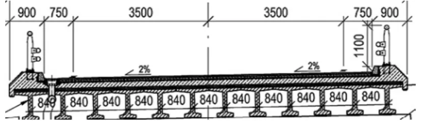
• pre-stressed string reinforced concrete beams (with and without diaphragm) (Figure 1);
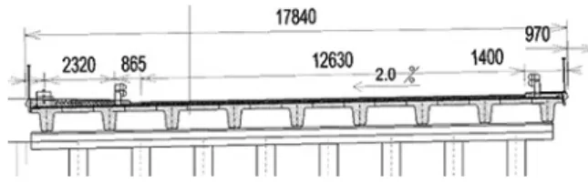
• pre-stressed beams (with wire rods) (Figure 2);
• multi-span continuous precast frame systems with trapezoidal cross-section beams (Figure 3).
Figures 4–9 shows the highest values of DAF for typical reinforced concrete structures in Latvia. The highest DAF value is calculated for the daily traffic load K44 with a weight of 52 t. The load is modelled as two
Figure 1. Cross-section of a bridge with pre-stressed string reinforced
304 THE BALTIC JOURNAL OF ROAD AND BRIDGE ENGINEERING
20 1 8/13 (3)
Figure 2. Cross-section of a bridge with pre-stressed beams
Figure 3. Cross-section of a bridge with trapezoidal cross-section beams
Figure 4. Frame-reinforced beams with diaphragms
Figure 5. Frame-reinforced beams without diaphragms
1 2 3 4 5 6 7 8 9 10 11 12 13
L = 11.36 m 0.2 0.2 0.2 0.2 0.2 0.3 0.3
L = 14.06 m 0.2 0.2 0.2
L = 1.76 m 0.2
L = 22.16 m 0.2 0.3
L = 8.66 m 0.1 0.2 0.2 0.2 0.3 0.3 0.3 0
0.5 1.0 1.5 2.0 2.5 3.0 3.5
DA
Fma
x
1 2 3 4 5 6 7 8
L = 11.36 m 2.2 2.7 2.8
L = 14.06 m 2.3 2.4 2.7
L = 16.76 m 1.7 2.1 2.2 2.5 0
0.5 1.0 1.5 2.0 2.5 3.0
DA
Fma
x
1 2 3 4 5 6 7 8 9 10 11 12 13
L = 11.36 m 0.2 0.2 0.2 0.2 0.2 0.3 0.3
L = 14.06 m 0.2 0.2 0.2
L = 1.76 m 0.2
L = 22.16 m 0.2 0.3
L = 8.66 m 0.1 0.2 0.2 0.2 0.3 0.3 0.3 0
0.5 1.0 1.5 2.0 2.5 3.0 3.5
DA
Fma
x
1 2 3 4 5 6 7 8
L = 11.36 m 2.2 2.7 2.8
L = 14.06 m 2.3 2.4 2.7
L = 16.76 m 1.7 2.1 2.2 2.5 0
0.5 1.0 1.5 2.0 2.5 3.0
DA
Fma
305
of the Increased Dynamic Effects on the Highway Bridge Superstructure (one after the other) vehicles. Bridges are assumed without significant
deteriorations and with standard pavement structure.
For the frame-reinforced beams with diaphragms (Figure 4) the highest DAF values were obtained for 22.16 m long span bridge. Lowest DAF values were obtained for 8.66 m long span bridge. Overall, the lowest DAF values are between 1.4 and 2.4 hence any DAF measured above 2.4 can be assumed as the maximum limit for this type of structures.
For frame-reinforced concrete beams without diaphragms (Figure 5) results show that lowest DAF value is 1.7 for 16.76 m span bridge. For 16.76 m long frame-reinforced beams with diaphragms, lowest DAF was 2.4. For frame-reinforced beams without diaphragms, DAF results are higher than they were for frame-reinforced beams with diaphragms.
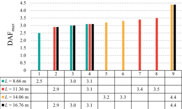
For pre-stressed string reinforced concrete beams with diaphragm (Figure 6) DAF values are much higher. The values are from 2.5 for 8.66 m long spans up to 3.2 for 14.06 m long spans with maximum DAF being 4.4 for 14.06 and 16.67 m long span bridges.
For pre-stressed string reinforced concrete beams without diaphragm (Figure 7) values are close to the DAF values for pre-stressed string reinforced concrete beams with diaphragm. Minimum DAF being 2.6 for 16.67 m long spans and 3.5 for 11.36 m long spans.
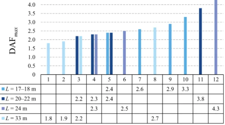
For pre-stressed beams (with wire rods) (Figure 8) there is the much greater distribution of values. For 33 m long spans minimum DAF is 1.8. However, all other typical spans have DAF starting from 2.2 hence 33.00 m long bridge spans are a structure that is more dynamic.
For multi-span continuous precast frame systems (Figure 9) with trapezoidal cross-section beams, the lowest DAF value is 1.3. These values are for span structures 15+21+15 m and 18+n·24+18 m.
Figure 6. Pre-stressed string reinforced concrete beams with the diaphragm
1 2 3 4 5 6 7 8 9
L = 8.66 m 2.5 3.0 3.1
L = 11.36 m 2.9 3.1 3.4 3.5
L = 14.06 m 3.2 3.3 4.4
L = 16.76 m 2.9 3.0 3.1 4.4
0 0.5 1.0 1.5 2.0 2.5 3.0 3.5 4.0 4.5 5.0 DA Fma x
1 2 3 4 5
L = 11.36 m 3.5 3.8
L = 14.06 m 3.0 3.3 3.5
L = 16.76 m 2.6 3.3 3.8
0 0.5 1.0 1.5 2.0 2.5 3.0 3.5 4.0 DA Fma x
1 2 3 4 5 6 7 8 9 10 11 12
L = 17–18 m 2.4 2.6 2.9 3.3
L = 20–22 m 2.2 2.3 2.4 3.8
L = 24 m 2.3 2.5 4.3
L = 33 m 1.8 1.9 2.2 2.7
306 THE BALTIC JOURNAL OF ROAD AND BRIDGE ENGINEERING
20 1 8/13 (3)
Figure 8. Pre-stressed beams (with wire rods)
Figure 9. Multi-span continuous precast frame systems with trapezoidal
cross-section beam size
Figure 7. Pre-stressed string reinforced concrete beams without diaphragm
1 2 3 4 5 6 7 8 9
L = 8.66 m 2.5 3.0 3.1
L = 11.36 m 2.9 3.1 3.4 3.5
L = 14.06 m 3.2 3.3 4.4
L = 16.76 m 2.9 3.0 3.1 4.4
0 0.5 1.0 1.5 2.0 2.5 3.0 3.5 4.0 4.5 5.0 DA Fma x
1 2 3 4 5
L = 11.36 m 3.5 3.8
L = 14.06 m 3.0 3.3 3.5
L = 16.76 m 2.6 3.3 3.8
0 0.5 1.0 1.5 2.0 2.5 3.0 3.5 4.0 DA Fma x
1 2 3 4 5 6 7 8 9 10 11 12
L = 17–18 m 2.4 2.6 2.9 3.3
L = 20–22 m 2.2 2.3 2.4 3.8
L = 24 m 2.3 2.5 4.3
L = 33 m 1.8 1.9 2.2 2.7
0 0.5 1.0 1.5 2.0 2.5 3.0 3.5 4.0 4.5 5.0 DA Fma x
1 2 3 4 5 6 7 8 9
L = 8.66 m 2.5 3.0 3.1
L = 11.36 m 2.9 3.1 3.4 3.5
L = 14.06 m 3.2 3.3 4.4
L = 16.76 m 2.9 3.0 3.1 4.4
0 0.5 1.0 1.5 2.0 2.5 3.0 3.5 4.0 4.5 5.0 DA Fma x
1 2 3 4 5
L = 11.36 m 3.5 3.8
L = 14.06 m 3.0 3.3 3.5
L = 16.76 m 2.6 3.3 3.8
0 0.5 1.0 1.5 2.0 2.5 3.0 3.5 4.0 DA Fma x
1 2 3 4 5 6 7 8 9 10 11 12
L = 17–18 m 2.4 2.6 2.9 3.3
L = 20–22 m 2.2 2.3 2.4 3.8
L = 24 m 2.3 2.5 4.3
L = 33 m 1.8 1.9 2.2 2.7
0 0.51.0 1.5 2.0 2.5 3.0 3.5 4.0 4.55.0 DA Fma x
1 2 3 4 5 6 7 8
L = 15+21+15 m 1.3 1.5
L = 15+18+15 m 1.8
L = 18+n∙24+18 m 1.3 1.7 2.0
L = 9+15+9 m;
9+18+9 m; 2.7 2.8 2.9
307
of the Increased Dynamic Effects on the Highway Bridge Superstructure Overall, lowest DAF values were found for frame-reinforced beams
with diaphragms and multi-span continuous precast frame systems with trapezoidal cross-section beams where maximum DAF was reached already at values 1.3 and 1.4. These DAF values show that these types of bridges in standard traffic conditions can reach maximum DAF value 1.4 which is included in the Eurocode load models (LVS EN 1991-2:2003 Traffic Loads on Bridges).
2. Evaluation criteria for increased dynamic
response
RC and PRC bridges built since 2000 have very variable cross-sections or span length. Each structure is unique. Hence, it is not possible to find a maximum DAF value for a bridge type or span length. However, it is possible to find a way to evaluate whetherthe structure is over-dynamic and what limits do dynamic parameters have. The Eq. (2) of morion show parameters which are considered while calculating dynamic properties:
m ∙ ϋ + c ∙ ύ + k ∙ u = F, (2) where m, c, and k are respectively mass, damping and stiffness and are acceleration, velocity and deflection, respectively. And forces acting on the structure are for the force of inertia (m·ϋ), viscose damping (c·ύ) and
elastic spring force or stiffness ((Brincker & Ventura, 2015). Stiffness is the only parameter that is calculated in the design process of a bridge (McGetrick, Kim, González, & Brien, 2015; OBrien, Rattigan, González,
Dowling, & Žnidarič, 2009).
With a full-scale dynamic and static bridge tests, it is possible to determine the necessary characteristics which show possibly higher DAF values. It was determined that those characteristics are natural frequency (first mode), damping ratio, relative deflection 1
span length static delection
, and span and depth ratio.
Analysis of the last 20 years bridge dynamic tests in Latvia has indicated the main geometric characteristics which show increased DAF values (Paeglite & Paeglitis, 2013; Paeglite, Smirnovs, & Paeglitis, 2016, 2017). These parameters are:
• span length and height ratio;
• bridge system – continuous, discontinuous or frame bridge;
• the bridge is in an angle to the longitudinal axis of the road;
308 THE BALTIC JOURNAL OF ROAD AND BRIDGE ENGINEERING
20 1 8/13 (3)
2.1. Reinforced concrete slab bridges
Reinforced concrete slab bridges are limited by their big self-weight hence to reduce the weight of the slab they are being manufactured with voids. These bridges are usually used in frame structures because their deflection is smaller than for simply supported structures (Mohammed & González, 2017).
Bridge geometry parameters which influence stiffness are – bridge structure is a frame system, or bridge is positioned in an angle to the longitudinal axis of the road.
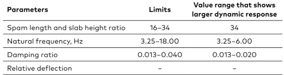
Table 1 shows the dynamic parameter limits for RC slab bridges. Larger relative deflection and span length and height ratio indicate increased DAF. Lowed damping ratio and natural frequency between 3.00 Hz and 6.00 Hz also show a high dynamic coefficient, but it strongly depends on the bridge type.
2.2. Pre-stressed beam bridges
There are many pre-stressed beam bridges in Latvia. This type of bridge was easy to produce, transport and erect on the construction site. These bridges have a relatively large load carrying capacity (Kwasniewski, Wekezer, Roufa, Li, Ducher, & Malachowski, 2006). They have simply supported beams without cantilevers. As these bridges were built mostly before 2000, they were rarely analysed for their dynamic properties. Dynamic testings were done after its reconstruction.
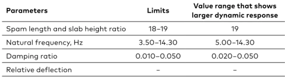
Table 2 shows dynamic parameter limits for pre-stressed beam bridges. These bridges are stiff and dynamic properties are lower than dynamic properties of RC slab bridge. However, higher damping ratio, a natural frequency between 5.00 Hz and 14.30 Hz, and smaller relative deflection indicate increased DAF.
Table 1. Values which indicate increased dynamic reaction for reinforced concrete slab bridges
Parameters Limits larger dynamic responseValue range that shows
Spam length and slab height ratio 16–34 34 Natural frequency, Hz 3.25–18.00 3.25–6.00 Damping ratio 0.013–0.040 0.013–0.020
309
of the Increased Dynamic Effects on the Highway Bridge Superstructure
2.3. Pre-stressed slab bridge
Pre-stressed slab bridges are widely used bridge type because it allows making slender structures (Benaim, 2007). However, these structures are much more dynamic than any beam or slab bridge. All the parameters that influence stiffness of the structure affect pre-stressed slab bridges. Hence, real dynamic parameters are much more difficult to obtain without dynamic tests. These bridges often have carriageway on cantilever hence it is possible to have torsional modes in lower frequencies.
Table 3 shows dynamic parameter limits for pre-stressed slab bridges. Pre-stressed slab deck has a small difference in span length and slab height ratio, i.e., from 24 to 26. The larger dynamic response indicates a natural frequency from 4.30 Hz to 4.50 Hz and a damping ratio from 0.030 to 0.040. Hence, if the carriageway is located on the cantilever, then it can cause increased dynamic performance and torsional deflection modes.
Table 2. Values which indicate increased dynamic reaction for pre-stressed beam bridges
Parameters Limits larger dynamic responseValue range that shows
Spam length and slab height ratio 18−19 19 Natural frequency, Hz 3.50–14.30 5.00−14.30 Damping ratio 0.010–0.050 0.020−0.050
Relative deflection − −
Table 3. Values which indicate increased dynamic reaction for pre-stressed slab bridges
Parameters Limits that shows larger Value range dynamic response
Parameters influencing dynamic
response Spam length and slab height ratio 24−26 25
Carriageway on a cantilever Natural frequency, Hz 2.50–5.20 4.30–4.50
Damping ratio 0.020–0.040 0.030–0.040
310 THE BALTIC JOURNAL OF ROAD AND BRIDGE ENGINEERING
20 1 8/13 (3)
2.4. Pre-stressed ribbed slab bridge
Pre-stressed ribbed slab bridges have almost the same structure as pre-stressed slab bridges. The difference is that much rarely carriageway is on the cantilever hence reducing possible torsional deflection modes. The advantage of this type of structure is that in the construction stage (if the bridge has even number of ribs) it is possible to build each side of the bridge separately.
Pre-stressed ribbed slab bridges are being influenced by all bridge stiffness parameters mentioned above in the paper. Hence, real dynamic parameters are much more difficult to obtain without dynamic tests.
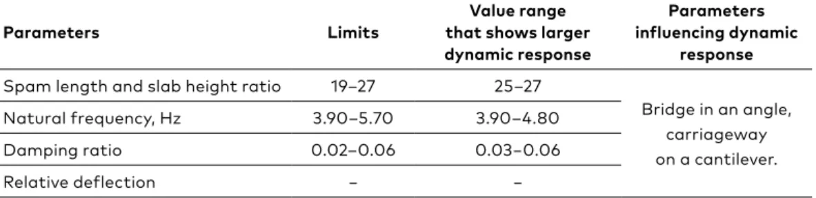
Table 4 shows dynamic parameter limits for pre-stressed ribbed slab bridges. Pre-stressed ribbed slab span length and slab height ratio from 25 to 27 and natural frequency from 3.9 Hz to 4.80 Hz indicate larger dynamic response. Smaller relative deflection, but higher damping ratio can indicate increased DAF values.
Conclusions
Increased dynamic effect on the highway bridge superstructure is an essential factor for both – bridges in use and recently built structures. The increased dynamic effect increases the structural deterioration speed and in the worst scenario cause significant damage to the structure.
In this paper, maximum Dynamic Amplification Factor was calculated for six different types of typical pre-stressed concrete beam bridges. The results have indicated that lowest Dynamic Amplification Factor values were found for the frame-reinforced beams with diaphragms and multi-span continuous precast frame systems with trapezoidal cross-section beams. For these structures maximum Dynamic Amplification Factor was reached already at values 1.3 to 1.4. 1.4 is the maximum Dynamic Table 4. Values which indicate increased dynamic reaction for pre-stressed ribbed slab bridges
Parameters Limits
Value range that shows larger dynamic response
Parameters influencing dynamic
response Spam length and slab height ratio 19–27 25–27
Bridge in an angle, carriageway on a cantilever. Natural frequency, Hz 3.90–5.70 3.90–4.80
Damping ratio 0.02–0.06 0.03−0.06
311
of the Increased Dynamic Effects on the Highway Bridge Superstructure Amplification Factor value included in LVS EN 1991-2:2003 Traffic Loads
on Bridges.
For recently built structures, it is difficult to find characteristic values of Dynamic Amplification Factor because of the unique structure and loading of every bridge. Hence, parameters which indicate increased dynamic response was found and analysed for four types of bridges. From the presented results, the following is concluded:
• natural frequency (first mode) from 4 Hz to 5 Hz showed
increased Dynamic Amplification Factor for all types of structures;
• damping ratio is less for all the structures, but pre-stressed concrete
structures with higher damping ratio of 0.020−0.060 indicate larger
Dynamic Amplification Factor;
• smallest relative deflection that indicates increased Dynamic
Amplification Factor is lower for reinforced concrete bridges − 1
1500 − 1
2030
1
3500 − 1
5080 . , but higher for ribbed pre-stressed slab bridges −
1
1500 − 1
2030
1
3500 − 1
5080 .
It was also concluded that geometric factors like a lane on the cantilever and bridge structure designed in an angle to the longitudinal axis of the road could significantly increase values of Dynamic Amplification Factor.
Acknowledgement
The research leading to these results has received the funding from Latvia state research programme under grant agreement “Innovative Materials and Smart Technologies for Environmental Safety, IMATEH”.
REFERENCES
Benaim, R. (2007). The design of prestressed concrete bridges: concepts and principles. CRC Press.
Brincker, R., & Ventura, C. (2015). Introduction to operational modal analysis. John Wiley & Sons. https://doi.org/10.1002/9781118535141
Carey, C., OBrien, E. J., Malekjafarian, A., Lydon, M., & Taylor, S. (2017). Direct field measurement of the dynamic amplification in a bridge. Mechanical Systems and Signal Processing, 85, 601-609.
https://doi.org/10.1016/j.ymssp.2016.08.044 Cebon, D. (1999). Handbook of vehicle-road interaction.
312 THE BALTIC JOURNAL OF ROAD AND BRIDGE ENGINEERING
20 1 8/13 (3)
Kwasniewski, L., Wekezer, J., Roufa, G., Li, H., Ducher, J., & Malachowski, J. (2006). Experimental evaluation of dynamic effects for a selected highway bridge. Journal of Performance of Constructed Facilities, 20(3), 253-260.
https://doi.org/10.1061/(ASCE)0887-3828(2006)20:3(253)
Lombaert, G., & Conte, J. P. (2012). Random vibration analysis of dynamic vehicle-bridge interaction due to road unevenness. Journal of Engineering Mechanics, 138(7), 816-825.
https://doi.org/10.1061/(ASCE)EM.1943-7889.0000386 LVS EN 1991-2:2003 Traffic loads on bridges
McGetrick, P. J., Kim, C. W., González, A., & Brien, E. J. (2015). Experimental validation of a drive-by stiffness identification method for bridge monitoring. Structural Health Monitoring, 14(4), 317-331.
https://doi.org/10.1177/1475921715578314
Mohammed, O., & González, A. (2017). Static and dynamic moments for any plane within a straight solid slab bridge caused by the crossing of a truck. Engineering Structures, 150, 465-480.
https://doi.org/10.1016/j.engstruct.2017.07.059
Mohammed, O., Gonzalez, A., & Cantero, D. (2018). Dynamic impact of heavy long vehicles with equally spaced axles on short-span highway bridges. Baltic journal of road and bridge engineering, 13(1), 1-13.
https://doi.org/10.3846/bjrbe.2018.382
OBrien, E. J., Rattigan, P., González, A., Dowling, J., & Žnidarič, A. (2009). Characteristic dynamic traffic load effects in bridges. Engineering structures, 31(7), 1607-1612. https://doi.org/10.1016/j.engstruct.2009.02.013
Oliva, J., Goicolea, J. M., Antolín, P., & Astiz, M. Á. (2013). Relevance of a complete road surface description in vehicle–bridge interaction dynamics. Engineering structures, 56, 466-476. https://doi.org/10.1016/j.engstruct.2013.05.029 Paeglite, I., & Paeglitis, A. (2013). The dynamic amplification factor of the
bridges in Latvia. Procedia Engineering, 57, 851-858. https://doi.org/10.1016/j.proeng.2013.04.108
Paeglite, I., Smirnovs, J., & Paeglitis, A. (2016). Traffic load effects on dynamic bridge performance. In Maintenance, Monitoring, Safety, Risk and Resilience of Bridges and Bridge Networks - Proceedings of the 8th International Conference on Bridge Maintenance, Safety and Management, IABMAS 2016. CRC Press. Paeglite, I., Smirnovs, J., & Paeglitis, A. (2017). Dynamic behavior of pre-stressed
slab bridges. Procedia Engineering, 172, 831-838. http://doi.org/10.1016/j.proeng.2017.02.132
Paeglitis, A., & Paeglitis, A. (2014). Traffic load models for Latvian road bridges with span length up to 30 meters. Baltic Journal of Road and Bridge Engineering, 9(2), 139-145. https://doi.org/10.3846/bjrbe.2014.18
Rezaiguia, A., Ouelaa, N., Laefer, D. F., & Guenfoud, S. (2015). Dynamic amplification of a multi-span, continuous orthotropic bridge deck under vehicular movement. Engineering Structures, 100, 718-730.
https://doi.org/10.1016/j.engstruct.2015.06.044