Proceedings of the Ninth Pacific Conference on Earthquake Engineering Building an Earthquake-Resilient Society 14-16 April, 2011, Auckland, New Zealand
Active Valve Control for Controlled Energy Release in Non-linear
Semi-Active Devices
Sylvain Corman, J. Geoffrey Chase, Gregory A. MacRae, Geoffrey W. Rodgers
University of Canterbury, Christchurch, New Zealand.
ABSTRACT: Semi-active devices are strictly dissipative, low power control devices designed to reduce seismic structural response damage in buildings using the building’s own motion to produce resistive forces. New semi-active resetable devices with independently controlled valves and chambers can sculpt the device and structural hysteresis loops for specific applications. However, some of the most advantageous hysteresis loops and applications are not possible without active valve control to control the release of stored energy, in contrast to current resetable device control laws that rely on a maximum, fixed rate of stored energy release.
This study uses proportional/derivative feedback control to closely track a desired, ideal reference force-displacement response curve. It is validated with a unique diamond-shaped control law under sinusoidal and seismically induced, random input motions. A spectral analysis is also done to compare the non-linear, actively controlled results to those obtained with an ideal, linear model. The results show tracking to within 3-5% of the desired force-displacement curve, with mean errors below 1%. Valve delay is the main limitation, where the ratio of valve delay to structural period must be 1/10 or smaller to ensure adequate tracking, thus prescribing valve performance as a function of the structural period of the application. The overall results show that active feedback control of energy release, via active control of the valves, can dramatically increase the design space of possible resetable device hysteresis loops that can be obtained, and thus significantly increase their performance envelope and application potential. The results and approach are fully generalisable to a wide range of energy dissipation devices.
1 INTRODUCTION
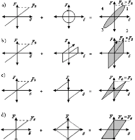
Semi-active control is emerging as an effective potential method of mitigating structural damage from large environmental loads, such as wind loading and seismic excitation. Resetable Semi-active devices are hydraulic spring elements with a resetable un-stretched spring length (Chase et al., 2006). If each chamber of a resetable device is independently controlled it offers the unique opportunity to sculpt or re-shape the structural hysteresis loop to meet design needs (Chase et al., 2006). Given a sinusoidal response input in the device, a typical viscously damped, linear structure has the hysteresis loop shown in Figure 1a. Figure 1b shows the same behaviour for a simple resetable device where all stored energy is released at the peak of each sine-wave cycle and all other motion is resisted. This form is denoted a “1-4 device” (Chase et al., 2006). However, Figure 1b shows that the resulting additional reaction loads from resisting motion away from equilibrium create additional demands on the foundation via increased total base-shear forces. If the control law is changed, such that only motion
towards the zero position (from the peak value) is resisted, the result is shown in Figure 1c, where base-shear demand is reduced by providing damping forces only in quadrants 2 and 4; a “2-4 device”. This device control law is only possible if each chamber of the device is independently controlled via independent valves, as shown schematically in Figure 2.
system yields a diamond-shaped force displacement behaviour, a “diamond” device. Active control of energy release with valve control thus offer the chance to get 1-4 device energy dissipation and displacement performance (or closer), in concert with the 2-4 device’s base shear force performance.
Figure 1. Schematic hysteresis for a) viscous damping, b) a 1-4 device, c) a 1-3 device, and d) a 2-4 device. FB = total base shear, FS = base shear for a linear, undamped structure. FB > FS indicates an increase due to the additional damping.
Figure 2: Single Degree of Freedom Structure Model with Semi Active Resetable Device
Non-linear device modeling (Mulligan et al., 2010) shows that this ideal linear diamond shape is hard to obtain without active valve control. It requires active controlled slow release of energy in quadrants 1 and 3 through active valve control and active in increase energy in quadrants 2 and 4 to linearize resistive force and avoid nonlinear dynamics inherent to these devices and working fluids. The valves for the actively controlled valve case studied herein could be readily implemented as either a single, analog controlled valve, or a cluster of independently controllable binary stable valves. This paper investigates the ability of active feedback control to produce an ideal, linear diamond-shaped control law for resetable devices using feedback valve control and nonlinear device models.
2 DEVICE DYNAMICS AND MODELLING
2.1 Structure-Device model
[image:2.595.179.415.404.497.2]2.2 Ideal Linear Device Control and Modelling
The ideal linear model is basically a linear resetable spring. Simple and easily understood, the control rules can be easily computed in classic finite element or other simulation software. Importantly, the actual characteristics of real device models, which are influenced by its dimensions (Mulligan et al., 2010), do not need to be considered. This model enables simple device specification and was used in prior spectral and design analyses (Mulligan et al., 2009, Rodgers et al., 2007), and is defined:
Fresetable = K (x - xreset) (1)
Where Fresetableis the resetable device force, x is the resetable device displacement, xreset is the resetable
device displacement at the time of the last valve reset (dependent on the control law) and K is the linear device stiffness, set to 100% column stiffness for comparison to (Rodgers et al., 2007). Figure 1 shows typical ideal device hysteresis loops, noting the ideal, instant energy release to zero force. 2.3 Nonlinear Device Model
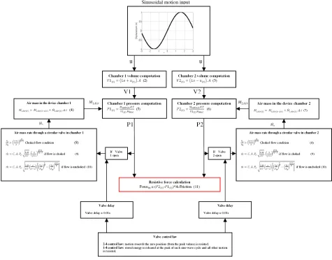
[image:3.595.64.539.322.694.2]The nonlinear model uses equations developed by (Mulligan et al., 2010) and validated with experimental data. For clarity and simplicity, Figure 3 shows the complete model equations and computational flow for a sinusoidal input motion (for clarity). The equations are shown this way to clearly show computational flow with the full derivation in (Mulligan et al., 2010).
Figure 3: Complete Nonlinear Model for Semi-Active Device
temperature, T, is taken as 293oK and the air molar mass, Mmol, is 0.02897 Kg.mol
-1
. The pressures in both chambers are used to calculate the mass flow rate through chambers, using to Equations 8-10. The variation of mass flow rate is dependent on the valve state, which is itself dependent upon both the overall valve control law (Figure 1) and the specific valve delay in implementing a control signal. Valve delay plays a critical role. It is composed of the delay between the command signal being sent to the valve and the solenoid receiving the signal, as well as the time taken for the valves to operate once the solenoid has received the command signal. Within this study, an average value of 0.01s is used, based on prior experimental and modeling work (Mulligan et al., 2010).
The air mass rate is used in Equations 4 and 7 to calculate the increase/decrease in pressure between the inside chamber and the outside. The pressure difference between the chamber and the ambient or fluid reservoir pressure is then reused in the pressure computations in Equations 5-6. Finally, the resistive force is calculated from the pressure difference between the chambers and the device friction force. The friction force was set at 500N (Mulligan et al., 2010) in this study using Equation 11, but can be set to any realistic or device-specific value. This overall computational loop in Figure 5 can readily be used to model a non linear device.
2.4 Active Valve Control
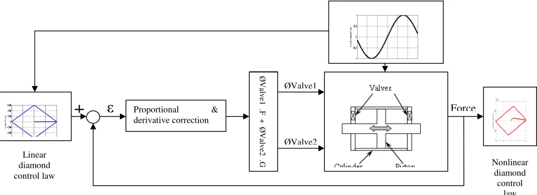
Feedback control is needed to produce a diamond-shaped control law. This feedback uses displacement and pressure information to compute the ideal valve opening at each step time step during energy release. Note that only the valve diameter on the working chamber needs to be calculated. The value on the non-working side is set to its maximum opening to avoid unwanted over atmospheric pressures that reduces the device’s resistive force.
[image:4.595.31.564.497.691.2]As shown in Figure 4, the output resistive force is set to track the projected linear trajectory Equation 11. At each time step, the difference of the device and ideal force trajectory are fed into a proportional and derivative (PD) controller. Equations 8 to 10 then give the necessary air mass rate for each chamber, proportional to pressure and valve diameter. As the valve delay time of 0.01s is fixed, the release rate capacity of each valve is calculated as the air mass released during that valve delay time period, assuming a constant shaft speed over that same delay period, which is acceptable for a small delay of 0.01s and a typical structure. Hence, under these approximations, an ideal valve diameter can be calculated at each time step. The proportional (P) and derivative (D) gains are found empirically using a basic iterative design method from control engineering texts.
Figure 4:Diamond shape control law feedback control loop for sinusoidal input example.
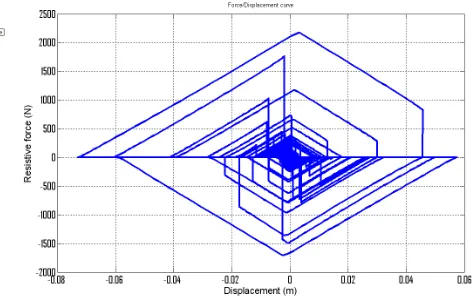
Figure 5 shows the resulting hysteresis loop for a typical ideal diamond-shaped control law given a random earthquake excitation of the single degree freedom structure of Figure 2. The negative release slope is kept the same for lack of better information, thus assuming that the response cycle will maintain the same amplitude of motion. At this point there are two different cases. First, the motion
Sinusoidal motion input
Force Ø V al v e1 . F + Ø V al v e2 . G ØValve1 ØValve2 Proportional &
suddenly changes direction due to random changes in seismic acceleration, but the resistive force is still nonzero. In this case, the opening of the two valves is reversed and the remaining stored energy is immediately released from one chamber, and (on valve closure) begins to increase in the opposite chamber. In the second case, the force reaches zero, but the motion continues in the same direction. In this case, the valve is allowed to open and wait for a change in direction of the motion. These two cases cover the situation where the motion reverses with smaller amplitude than the prior cycle (first case), and where it has a larger subsequent amplitude (second case). It is thus a simple, easily implemented device control approach to achieve complex overall device behaviour, and thus is ideal to assess its impact in this proof of concept analysis.
Figure 5: Typical force/displacement diamond control law for a single degree of freedom structure subject to a random earthquake excitation.
3 DEVICE DYNAMICS AND MODELLING
To validate this approach the following analyses are made:
• Sinusoidal input motions are imposed, which are an ideal and easy case to assess best achievable performance.
• Integration in a simple dynamic structure (Figure 2) under a single earthquake input to assess performance with a realistic random input case.
• Spectral analysis for 60 earthquakes from the SAC suite (Sommerville et al., 1997) to assess the impact of this control law on structural displacement and base shear across several motions and to compare to prior spectral analysis of 1-4 and 2-4 devices (Rodgers et al., 2007).
For earthquakes excitations, this research utilizes three earthquake suites from the SAC project, with 10 different time histories and two orthogonal directions for each history. The three suites represent ground motions having probabilities of excedance of 50% in 50 years, 10% in 50 years, and 2% in 50 years in the Los Angeles region, and are referred to as the low, medium and high suites. Response statistics are generated from the results of each probabilistically scaled suite.
Response spectra are generated for the structural displacement, the structural force, the total base shear force. The structural force is defined as the base shear for a linear, un-damped structure, whereas the total base shear is the sum of the structural force and the resisting forces from the semi-active resetable device. The structural force is thus an indication of the required column strength and the base shear is an indication of the required foundation strength.
[image:5.595.172.410.196.345.2]4 DEVICE DYNAMICS AND MODELLING
[image:6.595.99.493.139.377.2]4.1 Performance for Sinusoidal Input Motion
Figure 6 shows results for a sinusoidal motions and valve delay of 0.1s.
Figure 8: Force/displacement and valve opening for sinusoidal motion input of 0.2m amplitude and period of 5.0, 1.0 and 0.1s (left to right).
In Figure 6a with a 5.0s period, the diamond shape is nearly perfect with only a slight gap in quadrants 1 and 3 between the ideal reference force trajectory and the resulting effective resistive force. The valve opens and closes smoothly in Figure 6a (lower) without instability or saturation. From 5.0s to 1.0s of motion input period, the quality of diamond produced slowly decreases in Figure 6b. Abrupt changes in tracking force between quadrants 4 and 1 combines with valve delay causing the force to overshoot at the peaks. Hence, the active control valve cannot reduce the force as desired at these points. The results are worse for the 0.1s period.
More specifically, the period/valve delay ratio becomes non-negligible for short periods. At 5.0s period, with a 0.01s valve delay, the feedback controller can produce 500 corrections for each cycle. At 1.0s period, 100 corrections are available. Finally at 0.1s period only 10 corrections can be made limiting the controllers ability to track the desired diamond shape – a limiting factor.
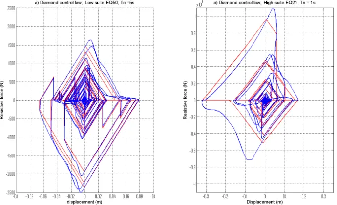
Figure 7 shows the same results for periods of 1.0s and 0.1s with a 10x smaller valve delay of 0.001s. The nominal valve diameter is increased to avoid saturation due to fast commanded valve motion in a short time. As expected, for a 1.0s period (Figure 9a) there is now a nearly perfect diamond shape. Figure 8 shows force-displacement results for the structure of Figure 3 for 2 randomly selected earthquakes from the SAC suites. The natural period is 5.0s for Figure 10a (left) and 1.0s for Figure 10b (right). They are subjected to a low and high suite event, respectively. The valve delay is 0.01s.As expected, the ideal diamond shape is not as good as in Figure 10b. However, both results are acceptable, as the active valve control shows no instability and never lost control of the device force. 4.2 Spectral Analyses
Figure7: Force/displacement and valve opening for sinusoidal motion input of 0.2m amplitude and period of 1 and 0.1s. Valve delay of 0.001s. Tracking force is red and device force is blue.
[image:7.595.115.483.71.288.2]Figure 8: Single degree of freedom structure and device hysteresis loop for a) 5s period and a low suite earthquake, and b) 1.0s period and a high suite earthquake.
[image:7.595.130.471.330.537.2]significant reductions for both base shear force and displacement (as seen in structural force). However, from 1.0 to 5.0s period, the reduction factors are slightly higher than expected due to the overshoot of resistive forces into quadrants 1 and 3 with the given 0.01s valve delay. Hence, at larger periods, where the overshoot of force causing these differences is less important, realistic model displacement reduction factors are very close to theoretically predicted values from the ideal, linear model. Below 1.0s period, we can observe significantly better reductions factors than expected from the ideal linear model because the forces are very high where the delay is a significant factor at very short periods of 0.2-0.3s. Hence, valve delay must be matched to structural period for good, results. Overall, the displacement and base shear reductions are as expected, at least where valve delay is not a factor. Displacement reductions are larger than for 2-4 devices, and smaller than for 1-4 devices. Similarly, base shear is still reduced, as expected, and in line with these results.
5 CONCLUSIONS
Control of resistive force in resetable semi-active devices using active valve control has been developed and implemented using a validated non-linear device model. The results show it to be effective and stable under random and quick changing loads, as are experienced in earthquakes. This approach is useful to produce the diamond shaped control law shown in this work, and opens several new possibilities for new and more effective control laws. With respect to the diamond-shaped control law presented, the diamond-shaped control law has the key advantages of decreasing structural force and displacement, as well as base shear force, with reduction factors of 0.55-0.7 and 0.7-0.8, respectively, for a spectral analysis across 60 ground motions and periods of 0.1-5.0s. However, the valve delay is also shown to be a critical factor, limiting the potential capability displayed. Results show that a minimum ratio of structural period to valve delay equal to 100-200 is required to achieve a consistent tracking of the ideal diamond-shape in this work, and this result will generalise similarly to other more complex inputs. Overall, the approach presented is generalisable to other semi-active devices that possess the ability to control resistive force in this way. Finally, the resetable device concepts and active valve control shown here offer the opportunity to greatly expand the design space of potential applications for such devices.
REFERENCES:
CHASE, J. G., MULLIGAN, K. J., GUE, A., ALNOT, T., RODGERS, G., MANDER, J. B., ELLIOTT, R., DEAM, B., CLEEVE, L. & HEATON, D. 2006. Re-shaping hysteretic behaviour using semi-active resettable device dampers. Engineering Structures, 28, 1418-1429.
MULLIGAN, K. J., CHASE, J. G., MANDER, J. B., RODGERS, G. W. & ELLIOTT, R. B. 2010. Nonlinear models and validation for resetable device design and enhanced force capacity. Structural Control & Health Monitoring, 17, 301-316.
MULLIGAN, K. J., CHASE, J. G., MANDER, J. B., RODGERS, G. W., ELLIOTT, R. B., FRANCO-ANAYA, R. & CARR, A. J. 2009. Experimental validation of semi-active resetable actuators in a 1/5th scale test structure. Earthquake Engineering & Structural Dynamics, 38, 517-536.
RODGERS, G. W., MANDER, J. B., CHASE, J. G., MULLIGAN, K. J., DEAM, B. L. & CARR, A. 2007. Re-shaping hysteretic behaviour - spectral analysis and design equations for semi-active structures.
Earthquake Engineering & Structural Dynamics, 36, 77-100.