TECHNICAL UNIVERSITY OF CLUJ-NAPOCA
ACTA TECHNICA NAPOCENSIS
Series: Applied Mathematics, Mechanics, and Engineering Vol. 62, Issue I, March, 2019
EXPERIMENTAL ANALYSIS ON DYNAMICS
OF VARIABLE MASS SYSTEM
Carmen DEBELEAC
Abstract: In this paper, the author studies the specific motion of mechanical system with low rates of mass variation. A variable mass–spring system has been developed using different materials for discharging (sand and gravel). Experimental procedure involves monitoring of the dynamics of expansion tank within the system configuration, along vertical direction, during the flow process of two materials.The spectral analysis of acquired acceleration, in terms of spectrum magnitudes and joint time-frequency spectrogram respectively, was considered, in order to evaluate the mass flow-rate equation. Comparative analysis between experimental and computational mass variation laws was performed, based on the tests acquirements and, respectively, on the available literature information.
Key words: variable mass system, experimental analysis, dynamics, mass flow-rate law, spectral analysis.
1. INTRODUCTION
Many applications in various fields of mechanical engineering contain machines or mechanisms with mass and position of their centre of mass and moment of inertia that vary during addition or removal of the material (generally identified as the systems with variable mass). Also, our days, specialty literature contains many researches about dynamic of mechanical system with various rates of mass variation that appear in technological process for loading/discharging of different materials used in construction, agriculture or food industry [1,3,6,7,10,13].
Thereby, Makharoblidze et al. [8] evaluated the basic operating parameters of machine-tractor unit taking into account the gradual increase or removing of agricultural materials masses. Castro et al. [2] and Digilov et al. [4] respectively studies the effect of the mass loss rate on the magnitude of the damping parameters for a spring pendulum, with the mass decreasing at a constant rate. In addition, Starosta et al., in paper [16], investigated the influence of mass change on the kinematics aspects of oscillations of two systems (namely the linear mass-spring oscillator and the
mathematical pendulum). Rodrigues et al. [14] analytically solved the motion of one-dimensional oscillator with time-varying mass using the Newton’s second law.
Syed, within his thesis [15], introduces and investigates a general method for measuring the flow of granular material through orifices. The effect of head, diameter of bin, diameter of orifice, roughness of bin walls and vibrations on the flow were experimentally studied [18]. In addition, a mathematical theory of the flow has been put forward and supported by the experiments.
An interesting study was presented in the paper [17], where the authors propose a detailed analysis regarding the stability of such kind of systems, treating the variable mass process influences on the global system dynamics.
2. EXPERIMENTAL SETUP
In order to perform the objective described in previous section, the author developed a laboratory experimental setup, based on an ensemble containing a variable mass device with the elastic linkage to the main grounded frame.
The experimental system used for the dynamics analysis of the variable mass system consists of the following components, namely:
•the expansion tank – used for storing and discharging the material that varies during the experiment;
•the storage tank – used to collect bulk material from the expansion tank during the experiment;
•the main frame for suspending the expansion tank;
•the basic support for hosting the storage tank;
•various materials to simulate the quantity of mass that varies during the experiment;
•an elastic device (metallic spring), used for simulating the rigidity of the expansion tank coupling with the base structure (frame). The configuration of the experimental setup (see the general view photo in Figure 1) were designed thus that it will allowed multiple possibilities to measure the parameters that are able to describe the system dynamics and, finally, to evaluate the mass flow law.
Fig. 1. General view of the experimental setup of the variable mass system
3. THEORTICAL BASICS
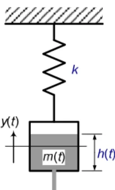
The schematization in Figure 2 depicts the basic configuration model of the experimental setup, and was adopted in order to allow some theoretical approaches regarding dynamic behaviour of the variable mass system.
Fig. 2. Model schematization of the oscillatory system with variable mass m(t) and instantaneously height h(t)
of flowing material, hanged by a spring with k stiffness
Within the first approximation, the friction phenomenon was neglected and the system was considered to be subjected to the action of three different forces, namely: the elastic force, the oscillator weight and the dynamic force due to the material flow within the discharging process.
Taking into account only vertical behaviour, then motion of this system can be described by the following equation
g m v dt dm y k dt
y d
m 2 =− − r − 2
, (1)
where y represents the position of the centre of mass, measured toward the repose position of the system, k denotes the stiffness coefficient of the elastic device (it is considered only linear characteristics), and
dt dy v
vr = − , (2)
where vr represents the relative flow rate of the
material.
When vr = 0 then =0
dt dm
and 2 0 2
=
dt y d
results such as
k g m
y0 =− 0 , where the m0 is the
initial oscillatory mass. For constant value of the parameter m0, the system provides
oscillatory motion around of y0 position.
By using coordinate transformation as 0
y y
y→ + results the absolute motion of the system described by the next equation
(
m m)
gv dt dm y k dt
y d
m 2 =− − r + 0− 2
. (3)
Hereby, the instantaneous position of equilibrium is given by the following expression
( )
( )
gk t m m t
y0 = 0− . (4)
The oscillatory mass system is obtained by adding the expansion tank mass and instantaneous mass of the material that will have flowing.
Within available specialty literature, different laws, related to the mass flow-rate of different materials, are provided. One of these, regarding the flowing of granular materials, has have following empirical expression [5, 9]
25 , 1 5 , 0
A g dt
dm ϕ ρ
= , (5)
where ρ represents the bulk density of flowing material, g means the acceleration of gravity, A denotes flowing area (outlet sectional area), and
ϕ is a parameter depending on specific discharge process characteristics.
4. TESTING PROCEDURE
Taken into account the experimental setup configuration, have been presented into the second section of this paper, the ensemble of force and acceleration transducers are able to provide information about dynamics of variable mass system as follows
•the force continuously developed in the coupling of the expansion tank to the rigid support frame;
•the force developed by the storage tank into its support structure;
•the acceleration of the expansion tank in the vertical direction;
•the residual accelerations in the vertical direction of the frame and, respectively, of the storage tank support.
Regarding the acceleration of the expansion tank along vertical direction, it has to be mentioned that this component have unrestricted motion during the experiment.
Hereby, the residual balancing motions of the tank (randomly initiated and supplied by the material discharging process) will affect the acceleration signal, with respect to the vertical direction, acquired by the transducer.
However, it will be shown into the discussions section that these residual balancing provides relatively significant weights only at the aperture opening and, respectively, during the final transitory regime, after the discharging process stops.
In Table 1, the microclimate conditions measured into the laboratory during the experiments was shown.
Table 1
Microclimate conditions Experiment
phase
Temperature [0C]
Pressure [mmHg]
Humidity [%]
Start 28 751 58
End 30 751 60
Pictures in Figure 3 show the measurement equipment and hardware used within the tests.
(a) (b)
(c) (d)
Fig. 3. Transducers and acquisition hardware: force transducer (a), piezoelectric accelerometers (b),
For the experimental analysis of the dynamics of the variable mass system, the following hypotheses were adopted
• two categories of testing materials (sand and gravel respectively);
• the mass varies within the range mmax→ 0; • the expansion tank (empty) has 0.300 kg;
• the stiffness of the hanging spring was experimentally determined (Figure 4).
(a)
(b) Fig. 4. The characteristics of the elastic element used for hanging the expansion tank, in terms of
force-deformation dependence (a) and, respectively, stiffness evolution with respect to deformation (b) According to the variation of spring stiffness within in-use deformation range, under 10%, for subsequent computations, it was adopted a constant value k = 0.30724 N/mm all-overs the entire domain.
The characteristics (density and mmax
respectively) of the granular materials, used as variable mass, were presented in Table 2.
Table 2
Granular material characteristics
Case Material Density [kg/m3]
Maximum value of variable mass mmax
[kg]
1 Sand 1600 1.00
2 Gravel 1346 1.00
The dimension of the grain, according to the two material categories, was (0.3...0.5) mm and (3.0...5.0) mm respectively. The discharging aperture (outlet) of the expansion tank has circular shape with 18 mm diameter. Hereby, the condition of continuously flowing was accomplished (available information within the literature proposed a range between 4...6 for the outlet to particle diameters ratio; during the experimental analyses, the author obtain that minimum value of this ratio can decrease to 2.85...2.90 in condition of avoiding the intermittencies and irreproducibility of material flow due to jamming).
On the other hand, the ratio between the tank and the outlet diameters respectively is greater than the literature proposed limit values, which assures that discharge rate does not depending on the tank diameter (proposed minimum value must rising above 2.5...2.6, and the experimental configuration have had 5 value of this ratio).
Other authors suggest that the independence of the flow rate to the tank diameter was assured when the difference between the container and the outlet diameters respectively exceeds thirty times the particle size.
gravel relative small deviation will be subsequently discussed.
Finally, it has to be mentioned that the experimental configuration and the previously hypotheses was adopted in order to assure a relative constancy of the flowing phenomenon and, hereby, supplying proper conditions to evaluate the influences induced by oscillations onto the discharging process.
5. RESULTS AND DISSCUSSIONS
The diagrams in Figure 5 present the raw acquired acceleration signals, with respect to time parameter, and the computational approaches of velocities and displacements respectively, for the sand (a) and for the gravel (b) category of material. According to the initial hypothesis, it was considered only the expansion tank motion along the vertical direction. Time domain was supposed to fully contains the discharge process (signals acquisition were started with a few seconds before the outlet opening) and almost the entirely afterwards transitory evolution of the expansion tank. During the process of material discharging disturbing oscillations occur (mainly vertical oscillations, unfortunately associated with transitory swinging motion, torsional and/or lateral oscillations) that were generated by the flow of the material and, obviously, it had maintained / intensified by throughout the process.
Following the proposed analysis procedure, in Figure 6 were depicted the diagrams of spectral composition and spectrograms respectively, in respect to the low frequency range that counts the goals of this study. The magnitude of acceleration spectrum was computed, and the relevant peaks were marked on the diagrams. Joint time-frequency analysis was additionally considered in order to facilitate the evaluation of the changes within the spectrum configuration due to the mass discharge process [12].
The continuous thick line on spectrograms depicts the peaks trend over the spectral area of interest. The two markers on each spectrogram denote suiting moments of mass flowing process start and stop respectively.
(a)
(b) Fig. 5. Timed evolutions (in terms of acceleration,
(a)
(b) Fig. 6. Spectral composition and spectrograms respectively of acceleration, for sand (a) - case 1,
and for gravel (b) - case 2.
(a)
(b) Fig. 7. Timed mass discharge and, respectively,
A comparative analysis of the acceleration spectrograms (corresponding to the two cases), revealed that the dynamic mode was more intense for the case of gravel material.
In respect with the hypothesis of a single degree of freedom model, briefly described in Section 3 of the paper, the frequency values provided by spectral diagrams help to evaluate the evolution of the variable mass (tank mass) during each experiment. Additionally, using a classical computational time-derivative routine, it was obtained the flow-rate diagram of the granular material. Hereby, the diagrams of the variable mass evolution and, respectively, of the mass flowing, in respect to time, were depicted in Figure 7, grouped for sand (a) and gravel (b) material type.
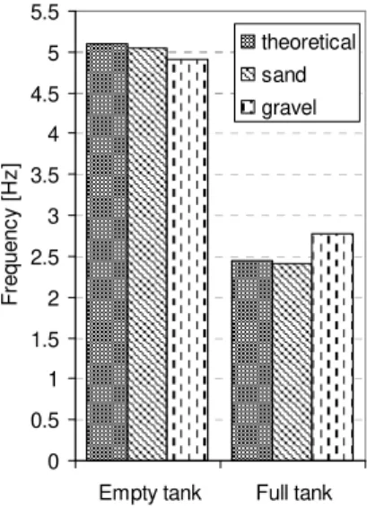
Taking into account theoretical and experimental values of maximum and minimum frequencies respectively, in Figure 8 was depicted a comparative histogram with respect to the limit status of the tank (full, empty). It has to underline the inappropriate value of gravel material fully tank, which leads to the idea that the total variable mass of the tank does not follows the initial hypothesis of 1.000 kg.
Supposing the single degree of freedom hypothesis results that, based on frequencies in Figure 8, it can evaluate the extremely values of the variable mass.
0 0.5 1 1.5 2 2.5 3 3.5 4 4.5 5 5.5
Empty tank Full tank
F re q u e n c y [ H z ] theoretical sand gravel
Fig. 8. Comparative analysis between the theoretical and experimental frequencies evaluated for both situations of charged tank (flow beginning) and
empty tank (flow stopping)
Following the previous paragraph observation, it can be notice that the maximum variable mass in case of gravel has around 0.700 kg. At this point, it can be formulating a first partial concluding remark that dynamic procedure of variable mass system investigation is able to provide accurate quantitative information about the process evolution.
A comparative analysis between these mass values was provided within the histogram in Figure 9. 0 .2 9 9 1 .2 9 7 0 .3 0 5 1 .3 2 9 0 .3 2 3 1 .0 0 7 0 0.1 0.2 0.3 0.4 0.5 0.6 0.7 0.8 0.9 1 1.1 1.2 1.3 1.4
Empty tank Full tank
M a s s [ k g ] theoretical sand gravel
Fig. 9. Comparative analysis between the theoretical and experimental mass values evaluated for both situations
of charged tank (flow beginning) and empty tank (flow stopping) according to the frequencies
within dynamic tests
Following the hypothesis of discharge process constancy, the timed mass discharges were fitted with the help of first order polynomials
( )
t m Q tm = 0 − m , (6)
where m0 denotes the tank mass and Qm
indicates the flow-rate of variable mass.
According with the two categories of material, it were obtained the following equations
( )
t tmsand =1.2901−0.09398 ⋅ , (7)
respectively
( )
t tObviously, supposing the flow-rate diagrams, it can easily evaluate the constant value of the material flow through averaging raw values, along the entirely time range of interest in discharging process (that are approximately 4...14 s. for sand and 5...14 s. for gravel). Hereby, the flow-rate mean values were depicted onto respective graphs and, respectively, mentioned into the diagrams legend (see Figure 6).
Such as it was presented into the first chapter, the available literature within the area of granular materials flowing, offers various expressions for discharging rate evaluation.
For the sake of comparison, it was adopted a basic formula of material flow-rate Qm,
proposed by W.R. Runo [15], for circular orifices, as follows
25 . 1 A
Qm =ξ ρ , (9)
where ρ denotes the specific bulk weight of material, A is the outlet area, and ξ denotes a specific coefficient that depends on material characteristics and flowing process.
Runo proposes, for circular outlets, that ξ = 0.85, obviously supposing the constant flow-rate of material [15]. Comparing the equation (9) with (5), results that the Runo's parameter ξ
is equivalent with
(
0,5)
gϕ product within (5). Taking into account the experimental acquired flow-rates of sand such as Qmsand =
0.0942 kgs-1 and gravel Q
mgravel = 0.0827 kgs-1
respectively, and following the empirical equation (9), result ϕsand = 0.7 and ϕgravel = 0.5,
comparatively with the ϕtheoretical = 0.27, derived from Runo's parameter ξ = 0.85, provided for a system with rigid supported tank.
In such conditions, it is obviously that tank oscillations lead to a certain amplification of discharge process, but depending on flowing material characteristics (density, grains dimension etc). Hereby, the author proposes a correction of ϕ coefficient as follows
b a dyn
d
ρ
ϕ = , (10)
where ϕdyn denotes dynamic coefficient
depending on a power of density and b power of grain dimension, with a, b real constants. According to the experimental values, the two constants are a = -0.02005 and b = -0.1443. Hereby, the augmented formula (5), also taking into account equation (9), yields
25 . 1 5 . 0 *
A g
Q dyn
m =ϕ ϕ ρ , (11)
where ϕ* 0.5 =ξ
g denotes the initial value proposed by Runo (actually, ϕ* = ϕtheoretical with
previously mentioned constant value).
According to the flow-rate values (and, respectively, of the variable mass) derived from both dynamic procedure and theoretical approaches, it can be evaluate the relative error between the two situations. The results were shown in Table 3, with respect in material type and tank status.
Table 3
The relative errors of mass evaluation
Flowing material
Tank status
Real value of mass
[kg]
Error [%]
sand empty 0.3503 12.9 full 1.2901 3.0 gravel empty full 0.3644 1.1112 11.4 9.4
The larger errors has appears for the ending of the process that is relatively accountable due to the partial incompletely discharge of the tank. The last remark has to taken into account the correlation of the grains dimension and shape with the outlet configuration (in fact, with the geometry of the hopper bottom part including the outlet aperture).
This fact was experimentally observed during the tests, when the gravel provides less amount of remained material into the expansion tank then the sand.
acceleration on main monitored vertical direction.
Experimental investigations related to this fact had shown that were smallest comparing with the main signal parameters, but unavoidable within the proposed testing setup.
The author accepts this situation because of its good approximation with the real situation (taking into account the direct applicability of this study within the area of equipments for construction material handling).
6. CONCLUSIONS
The novelty of this study is the approach of the dynamics of systems with relatively reduced velocities of variable-mass based on the experimental analysis of oscillations of the whole ensemble.
The entirely procedure was exclusively based on acceleration measurements during the system evolution, without any additional information supplied by the force transducers.
The ensemble of experimental results leads to the conclusion that proposed method is able to provide accurate characterization of such systems with variable mass.
Starting from the necessity to analyze the transitory dynamics induced within the structure of the construction equipments on the material loading / unloading processes, this study, even it exclusively reports preliminary results related to only two kind of material, provides useful and serviceable information for such machineries designing operational procedures.
Obviously, the future investigations will be focused on other granular material (from construction area and beyond this) as variable mass within the dynamic system, and, in addition, on increasing the accuracy of the method for dynamic data characterization, in order to minimize the flow-rate error evaluation.
The improvement in parameters estimation, with the main purpose into the quantitative conformity characterization, will be discussed in a forthcoming work.
Supplementary, it will be follows the diminishing of the transitory phenomenon on the tests, both at the process beginning (when the outlet is opened) and, respectively, during the material discharging (through minimizing the parasitic oscillations of the expansion tank within the experimental tests, but keeping the realistic correlation with the practice phenomenology).
7. REFERENCES
[1]Banerjee, A. K., Dynamics of a Variable-Mass, Flexible-Body System, Journal of Guidance, Control and Dynamics, Vol. 23, No. 3, pp. 501-508, 2000
[2]Castro, F., Tomé, P.S., Neto, S., Ortiz, E., Estudo de um sistema oscilante com massa variável, Blucher Physics Proceedings, Abril, Número 2, Volume 1, 2014
[3]Celia A. de Sousa, Vitor H. Rodrigues, Mass distribution in variable mass system, European Journal of Physics, vol. 25, pp. 41-49, 2004
[4]Digilov, R.-M., Reiner, M., Weizman, Z., Damping in a variable mass on a spring pendulum, American Journal of Physics, Vol. 73, No. 10, pp. 901-905, 2005
[5]Flores, J., Solovey, G., Gil, S., Flow of sand and a variable mass Atwood machine, American Journal of Physics, vol. 71, Issue 7, pp. 715 - 720, July, 2003
[6]Guillaume, P., Regularization of the two body problem with variable mass, Vol. 10, Issue 2, pp. 141–149, 1974
[7] Lupea, I., Considerations on an elementary fluid-structure coupling system, Acta Technica Napocensis Series: Applied Mathematics, Mechanics, and Engineering Vol. 57, Issue IV, November, 2014 pp.487-492
[8]Makharoblidze, R. M., Lagvilava, I. M., Basilashvili, B. B., Khazhomia, R. M., Dynamics calculation with variable mass of mountain self-propelled chassis, Annals of Agrarian Science, Vol. 14, Issue 4, Pages 340-342, 2014
[10]Moholea, I.F., Popescu, D.I., Ursu-Fischer, N., Contributions to the study of the masses chaotic movements of a mechanical system, Acta Technica Napocensis Series: Applied Mathematics, Mechanics, and Engineering Vol. 58, Issue III, September, 2015 pp. 435-440
[11]Negrean, I., Mass distribution in analytical dynamics of systems, Acta Technica Napocensis Series: Applied Mathematics, Mechanics, and Engineering Vol. 60, Issue II, June, 2017, pp. 175-184
[12]Nastac, S., On Damage Detection in Beams Based on Dynamic Tests and Transitory Analysis, The Annals of "Eftimie Murgu" University of Reșița, Engineering
Fascicle, Year XX, No.3, pp. 164-170, 2013 [13]Pop, E., Steopan, M., Ciupan, C., Filip, I., Decreasing the mass of a sofa side made of composite materials based on vegetable fibers, Acta Technica Napocensis Series: Applied Mathematics, Mechanics, and Engineering Vol. 61, Issue IV, November, 2018, pp. 775-780
[14]Rodrigues, H., Panza, N., Portes Jr. D., Soares, A., A model of oscillator with variable mass, Revista Mexicana de Fısica, Vol. 60, pp. 31–38, 2014
[15]Syed Iftikhar Ahmed. Flow of granular material through orifices, Thesis, McGill University, Montreal, 1959
[16]Starosta, R., Sypniewska-Kamińska, G.,
Awrejcewicz, J., Vibration of the Oscillator Exchanging Mass with Surroundings, Vibrations in Physical Systems, Vol. 27, pp. 333- 338, 2016
[17]Tuge, C., Gezahegn, N., Stability Analysis of Dynamics of Variable Mass System, Asian Journal of Applied Science and Technology - AJAST, Vol. 1, Issue 9, pp. 305-313, 2017
[18]Wanghua Sui, Yankun Liang, Xinjia Zhang, Ravi Jain & Tao Zhu, An experimental investigation on the speed of sand flow through a fixed porous bed, Scientific Reports, volume 7, Article number: 54, 2017.
Analiza experimentală a dinamicii unui sistem cu masă variabilă
Rezumat: În această lucrare, autorul studiază mișcarea unui sistem mecanic cu viteză redusă de variație a masei. A fost
considerat un sistem experimental de laborator, format dintr-un oscilator cu un singur grad de libertate și s-au
utilizat două tipuri de materiale pentru variația masei (respectiv nisip și pietriș). Metoda experimentală utilizată
implică monitorizarea dinamicii vasului de expansiune al sistemului, pe direcție verticală, în timpul curgerii celor
două tipuri de materiale. Spectrul de frecvență (amplitudinea acestuia) și, respectiv, variația continuă a acestuia pe
întreaga durată a experimentului (spectrograma), au fost utilizate pentru evaluarea legii de variație a masei și,
respectiv, a ecuației debitului masic. În final, au fost analizate comparativ rezultatele obținute experimental cu cele
estimate pe baza relațiilor empirice oferite de literatura de specialitate.
![Table 1 Microclimate conditions Experiment phase Temperature [ 0 C] Pressure [mmHg] Humidity [%] Start 28 751 58 End 30 751 60](https://thumb-us.123doks.com/thumbv2/123dok_us/7995390.2120174/3.918.495.819.790.998/table-microclimate-conditions-experiment-temperature-pressure-humidity-start.webp)