Junos
®
OS
Session Border Control Solutions Guide Using BGF
and IMSG
Release
11.2
This product includes the Envoy SNMP Engine, developed by Epilogue Technology, an Integrated Systems Company. Copyright © 1986-1997, Epilogue Technology Corporation. All rights reserved. This program and its documentation were developed at private expense, and no part of them is in the public domain.
This product includes memory allocation software developed by Mark Moraes, copyright © 1988, 1989, 1993, University of Toronto. This product includes FreeBSD software developed by the University of California, Berkeley, and its contributors. All of the documentation and software included in the 4.4BSD and 4.4BSD-Lite Releases is copyrighted by the Regents of the University of California. Copyright © 1979, 1980, 1983, 1986, 1988, 1989, 1991, 1992, 1993, 1994. The Regents of the University of California. All rights reserved.
GateD software copyright © 1995, the Regents of the University. All rights reserved. Gate Daemon was originated and developed through release 3.0 by Cornell University and its collaborators. Gated is based on Kirton’s EGP, UC Berkeley’s routing daemon (routed), and DCN’s HELLO routing protocol. Development of Gated has been supported in part by the National Science Foundation. Portions of the GateD software copyright © 1988, Regents of the University of California. All rights reserved. Portions of the GateD software copyright © 1991, D. L. S. Associates.
This product includes software developed by Maker Communications, Inc., copyright © 1996, 1997, Maker Communications, Inc. Juniper Networks, Junos, Steel-Belted Radius, NetScreen, and ScreenOS are registered trademarks of Juniper Networks, Inc. in the United States and other countries. The Juniper Networks Logo, the Junos logo, and JunosE are trademarks of Juniper Networks, Inc. All other trademarks, service marks, registered trademarks, or registered service marks are the property of their respective owners.
Juniper Networks assumes no responsibility for any inaccuracies in this document. Juniper Networks reserves the right to change, modify, transfer, or otherwise revise this publication without notice.
Products made or sold by Juniper Networks or components thereof might be covered by one or more of the following patents that are owned by or licensed to Juniper Networks: U.S. Patent Nos. 5,473,599, 5,905,725, 5,909,440, 6,192,051, 6,333,650, 6,359,479, 6,406,312, 6,429,706, 6,459,579, 6,493,347, 6,538,518, 6,538,899, 6,552,918, 6,567,902, 6,578,186, and 6,590,785.
Junos®OS Session Border Control Solutions Guide Using BGF and IMSG Release 11.2
Copyright © 2011, Juniper Networks, Inc. All rights reserved.
Revision History May 2011—R1 Junos 11.2
The information in this document is current as of the date listed in the revision history. YEAR 2000 NOTICE
Juniper Networks hardware and software products are Year 2000 compliant. Junos OS has no known time-related limitations through the year 2038. However, the NTP application is known to have some difficulty in the year 2036.
END USER LICENSE AGREEMENT
The Juniper Networks product that is the subject of this technical documentation consists of (or is intended for use with) Juniper Networks software. Use of such software is subject to the terms and conditions of the End User License Agreement (“EULA”) posted at
http://www.juniper.net/support/eula.html. By downloading, installing or using such software, you agree to the terms and conditions of that EULA.
Abbreviated Table of Contents
About This Guide . . . xix
Part 1
BGF VoIP Solution
Chapter 1 BGF VoIP Solution Overview . . . 3Chapter 2 Configuring the BGF . . . 29
Chapter 3 Monitoring the BGF . . . 63
Chapter 4 Managing the BGF . . . 81
Chapter 5 Upgrade Guidelines for BGF VoIP Users . . . 105
Chapter 6 Maintenance and Failover in the BGF . . . 107
Chapter 7 Troubleshooting the BGF . . . 117
Chapter 8 Example: Using the BGF to Provide VoIP Solutions in a Next-Generation Network . . . 123
Part 2
IMSG VoIP Solution
Chapter 9 Overview of the IMSG . . . 151Chapter 10 Configuring the IMSG . . . 173
Chapter 11 Monitoring the IMSG . . . 207
Chapter 12 Managing the IMSG . . . 215
Chapter 13 Maintenance and Failover in the IMSG . . . 219
Chapter 14 Troubleshooting the IMSG . . . 223
Chapter 15 Example: Using the IMSG to Provide VoIP Solutions in a Next-Generation Network . . . 227
Part 3
Index
Index . . . 287Table of Contents
About This Guide . . . xix
JUNOS Documentation and Release Notes . . . xix
Objectives . . . xix
Audience . . . xx
Using the Indexes . . . xx
Documentation Conventions . . . xx
Documentation Feedback . . . xxii
Requesting Technical Support . . . xxii
Self-Help Online Tools and Resources . . . xxiii
Opening a Case with JTAC . . . xxiii
Part 1
BGF VoIP Solution
Chapter 1 BGF VoIP Solution Overview . . . 3BGF VoIP Solution Overview . . . 3
The BGF VoIP Solution in a Next-Generation Network Overview . . . 3
BGF VoIP Solution Terms and Abbreviations . . . 4
Supported Hardware Platforms for the BGF . . . 5
BGF VoIP Solution Architecture . . . 6
BGF Architecture Diagram . . . 6
Gateway Controller . . . 6
BGF . . . 7
PGCP . . . 7
BGF Topology with Multiple Virtual BGFs and Gateway Controllers Overview . . . . 7
Sample BGF Voice Network Topology . . . 9
Control of Voice Flows with Gates Overview . . . 10
Using Gates for Voice Flows . . . 10
Gate Addressing . . . 10
Gate Opening, Closing, and Modification Overview . . . 11
Gate Identification . . . 11
Forward and Drop Operations for RTP and RTCP Gates . . . 11
Explicit and Implicit Latching . . . 12
Latch Deadlock and Media Inactivity Detection and Reporting . . . 12
Detection . . . 12
Reporting . . . 13
H.248 Building Blocks Overview . . . 13
H.248 Components . . . 13
Terminations . . . 14
Contexts . . . 14
Streams . . . 14
Twice NAT for VoIP Traffic Overview . . . 15
Introduction to Twice NAT . . . 15
NAT Pool Selection . . . 16
NAT Pool Selection by Matching the Transport Protocol . . . 16
IPv4-to-IPv6 Address Translation . . . 17
Quality of Service for VoIP Traffic Overview . . . 17
Rate-Limiting for VoIP Traffic Overview . . . 18
Introduction to Rate Limiting . . . 18
How the Rate Limiting Feature Works . . . 18
Default Values for Rate-Limiting Parameters . . . 19
Rate Limiting and Fast Update Filters . . . 19
Rate-Limiting Statistics Display . . . 20
Security for BGF Overview . . . 20
Protecting H.248 Messages and Mirrored Sessions with IPsec Overview . . . 20
Interim AH Scheme . . . 21
Symmetric Control Association . . . 21
Priority and Emergency Call Handling . . . 21
BGF VoIP Call Setup Overview . . . 22
VPN Aggregation for VoIP Calls Overview . . . 23
Introduction to VPN Aggregation . . . 23
How VPN Aggregation Works . . . 24
Session Mirroring Overview . . . 25
Session Mirroring Introduction . . . 25
Activation of Session Mirroring for a Gate . . . 26
How Session Mirroring Works . . . 26
Protecting Mirrored Sessions with IPsec Overview . . . 27
Chapter 2 Configuring the BGF . . . 29
Configuring Virtual BGFs to Run on Services PICs . . . 29
Enabling the BGF Service Package on the PIC or DPC . . . 30
Configuring the Control Services PIC or DPC for the Virtual BGF . . . 31
Configuring a Virtual BGF . . . 32
Adding a Gateway Controller to the Virtual BGF Configuration . . . 33
Configuring the H.248 Profile . . . 34
Configuring NAT Pools for the BGF . . . 34
Configuring a Remotely Controlled NAT Pool . . . 34
Configuring a NAT Pool Selected Based on Transport Protocol . . . 35
Configuring Virtual Interfaces . . . 36
Creating a Rule That Specifies the NAT Pool to Use on a Virtual BGF . . . 36
Specifying the Order in Which the BGF Processes Rules . . . 37
Configuring a Stateful Firewall for the BGF . . . 37
Configuring a Service Set . . . 38
Configuring Rate Limiting for the BGF . . . 39
Configuring QoS for the BGF . . . 40
Configuring the Data Services PIC or MS-DPC . . . 40
Configuring VPN Aggregation . . . 41
Configuring Implicit Latching for TCP Gates . . . 44
Configuring IPsec to Protect H.248 Messages or Mirrored Sessions in Tunnel
Mode . . . 45
Configuring IPsec to Protect H.248 Messages in Transport Mode . . . 47
Configuring H.248 Base Root Properties . . . 47
Configuring H.248 Segmentation Properties . . . 50
Configuring Session Mirroring . . . 51
Setting Up Session Mirroring . . . 52
Configuring IPsec to Protect Mirrored Sessions in Tunnel Mode . . . 53
Disabling Session Mirroring . . . 54
Re-Enabling Session Mirroring . . . 54
Verifying Your Configuration . . . 54
Verifying the BGF Configuration . . . 55
Verifying the BGF Service Package Configuration . . . 57
Verifying the Control Service PIC Configuration . . . 57
Verifying the Service Interface Configuration . . . 58
Verifying the Service Set Configuration . . . 58
Verifying the NAT Pool Configuration for a Remotely Controlled NAT Pool . . . 59
Verifying the NAT Pool Configuration for a Transport Protocol-Based NAT Pool . . . 59
Verifying the Stateful Firewall Configuration . . . 59
Verifying the VPN Aggregation Configuration . . . 60
Verifying VPN Aggregation Policy Options Configuration . . . 60
Verifying VPN Aggregation Routing Instances Configuration . . . 60
Verifying VPN Aggregation Service Set Configuration . . . 60
Verifying VPN Aggregation Service Interface Pool Configuration . . . 61
Verifying VPN Aggregation Virtual Interface Configuration . . . 61
Chapter 3 Monitoring the BGF . . . 63
Monitoring RTP and RTCP Traffic . . . 63
Monitoring Gates . . . 64
Displaying Information About All Gates on a Virtual BGF . . . 65
Displaying Extensive Information About All Gates on a Virtual BGF . . . 66
Displaying the Number of Gates Installed on a Virtual BGF . . . 67
Displaying Information About a Specific Gate . . . 67
Displaying Extensive Information About a Specific Gate . . . 67
Displaying Statistics for Gates . . . 68
Collecting Statistics on Gates with Rate-Limited Flows . . . 69
Improving Performance While Collecting Gate Statistics . . . 69
Displaying the Number of FUF Terms Installed on a Virtual BGF . . . 69
Displaying Gates That Are Being Mirrored . . . 70
Monitoring Terminations . . . 70
Displaying Information About All Terminations on a Virtual BGF . . . 70
Displaying Information About Terminations in H.248 Format . . . 70
Displaying Information About Specific Terminations . . . 73
Monitoring PGCP Root Terminations . . . 74
Monitoring Statistics for the Virtual BGF . . . 75
Monitoring Flows . . . 76
Displaying All Flows . . . 77
Displaying Extensive Information About All Flows . . . 77
Displaying Extensive Information About Flows for a Specific Gate . . . 78
Monitoring Conversations . . . 78
Displaying All Conversations . . . 79
Displaying Extensive Information About All Conversations . . . 80
Chapter 4 Managing the BGF . . . 81
Managing the pgcpd Process Running on a Routing Engine . . . 81
Restarting the pgcpd Process Running on the Routing Engine . . . 82
Disabling and Enabling the pgcpd Process . . . 82
Activating and Deactivating PGCP Services Running on the Routing Engine . . . 83
Managing the pgcpd Process Running on a Services PIC . . . 83
Restarting the pgcpd Process Running on a Services PIC . . . 83
Deactivating the PGCP Service . . . 84
Activating the PGCP Service . . . 84
Shutting Down a Virtual BGF . . . 84
Forcing the Shutdown of a Virtual BGF . . . 84
Performing a Graceful Shutdown of a Virtual BGF . . . 84
Allowing Emergency Calls While the BGF Is Draining . . . 85
Making the Virtual BGF Operational Again . . . 85
Shutting Down a Virtual Interface . . . 85
Forcing the Shutdown of a Virtual Interface . . . 85
Performing a Graceful Shutdown of a Virtual Interface . . . 86
Making the Virtual Interface Operational Again . . . 86
Maintaining Synchronization Between the BGF and the Gateway Controller . . . . 86
Detecting Hanging Terminations . . . 86
Activating and Configuring Hanging Termination Detection . . . 87
Deactivating Hanging Termination Detection . . . 87
Displaying the Value of the Timerx Timer Configured on the Virtual BGF . . . 87
Displaying the Value of the Hanging Termination Timer for a Termination . . . 87
Detecting Gateway Controller Failures . . . 88
Maintaining Synchronization by Auditing Terminations . . . 89
Using AND/OR Logic with Audit Commands . . . 89
Example: Audit Section Filter with AND Logic . . . 90
Example: Audit Section Filter with OR Logic . . . 90
Managing Overload Control with Priority Handling for Emergency Calls . . . 91
Configuring Overload Control for Voice Calls . . . 91
Preventing Excessive Media Inactivity Notifications . . . 92
Configuring H.248 Notification Behavior to Prevent Excessive Media Inactivity Notifications . . . 93
Managing the Rate for All Notifications Sent by a PIC or DPC . . . 94
Controlling ServiceChange Commands Sent from the Virtual BGF to the Gateway
Controller . . . 95
Control Association States . . . 95
Method and Reason Options for Control Association State Changes . . 96
Virtual Interface States . . . 98
Method and Reason Options for Virtual Interface State Changes . . . 99
Context States . . . 100
Configuring the Method and Reason in Service Change Commands . . . 101
Configuring the Method and Reason in ServiceChange Commands for Control Associations . . . 101
Configuring the Method and Reason in ServiceChange Commands for Virtual Interfaces . . . 102
Configuring the Method and Reason in ServiceChange Commands for Contexts . . . 103
Chapter 5 Upgrade Guidelines for BGF VoIP Users . . . 105
Upgrade Overview for BGF VoIP Users . . . 105
Managing Emergency and Non-Emergency Call Traffic Prior to Upgrading . . . . 106
Chapter 6 Maintenance and Failover in the BGF . . . 107
Maintenance and Failover in the BGF Overview . . . 107
Failover in Case of a Routing Engine Failure . . . 108
Gate Synchronization Procedure . . . 108
Configuring Synchronization Properties in Case of Routing Engine Failure . . . 109
Displaying the Status of the Routing Engine Synchronization . . . 109
Failover of the Data Service PICs . . . 110
Procedure in Case of Data PIC Failure . . . 110
Configuring the BGF for Data Service PIC Redundancy . . . 111
Configuring the Redundancy Services PIC (rsp) Interface . . . 111
Configuring the Service Set for Redundant Services PICS . . . 112
Manually Switching from the Primary PIC to the Secondary PIC . . . 112
Manually Reverting from the Secondary PIC to the Primary PIC . . . 112
Displaying the Status of the Redundant Service PICs . . . 113
Failover of the Control Service PICs . . . 113
Configuring the rms Interface . . . 114
Specifying the rms Interface as the Platform Device for the Virtual BGF . . . . 115
Manually Switching from the Primary Control Services PIC to the Secondary PIC . . . 115
Manually Reverting from the Secondary PIC to the Primary PIC . . . 115
Displaying the Status of the Redundant Service PICs . . . 115
Chapter 7 Troubleshooting the BGF . . . 117
Tracing BGF Operations . . . 117
Tracing BGF Operations for a Specific Control Services PIC . . . 118
Logging Messages for the pgcpd Process Running on the Routing Engine . . . 119
Logging H.248 Messages . . . 120
Fields in the H.248 Messages . . . 120
Messages That Exceed Output Buffer Limit . . . 121
Configuring Logging of H.248 Messages . . . 122
Chapter 8 Example: Using the BGF to Provide VoIP Solutions in a Next-Generation
Network . . . 123
Example: Using the BGF to Provide VoIP Solutions in a Next-Generation Network . . . 123
Part 2
IMSG VoIP Solution
Chapter 9 Overview of the IMSG . . . 151IMSG Session Border Control Solution Overview . . . 151
IMSG Terms and Abbreviations . . . 152
Supported Hardware Platforms for the IMSG . . . 153
IMSG Architecture Overview . . . 154
BGF . . . 154
BSG . . . 154
SPDF . . . 155
How the SPDF Works . . . 155
IPS and FW Applications . . . 155
IPsec . . . 156
IMSG Scalability . . . 156
BSG Policy Overview . . . 156
Types of BSG Policies . . . 156
BSG Policy Model . . . 157
Policy Sets . . . 157
Service Points . . . 157
Policy Configuration Limits . . . 158
Manipulation of Headers and Request URIs in SIP Messages . . . 158
How Header Manipulation Works . . . 159
Applying Message Manipulation Rules . . . 159
Header Manipulation Examples . . . 159
Example: Removing a Text String from the Alert-Info Field . . . 159
Example: Rejecting a Message Based on the Field Value of the From Header . . . 160
Example: Using a Regular Expression to Modify the P-Asserted-Identity Field Value . . . 160
Example: Adding the Transport Protocol and “q” Parameter to the Contact Header . . . 160
Using High Availability with Message Manipulation . . . 161
Displaying Message Manipulation Rules That Are Currently Being Applied . . . 161
Media Anchoring Overview . . . 161
SIP Routing Overview . . . 162
SIP Routing with Server Clusters Overview . . . 162
Availability Checking for Server Clusters . . . 163
Server Definition for Server Clusters . . . 163
Server Cluster Definition . . . 164
Locating SIP Servers Using DNS Overview . . . 164
How the DNS Resolution Process Works . . . 165
Server Clusters . . . 166
Virtual Interfaces and NAT Pool Assignment with the IMSG . . . 166
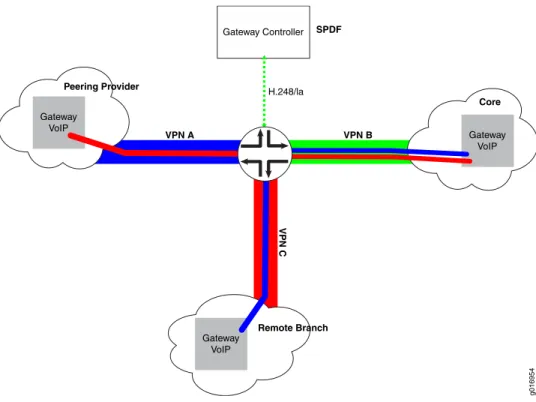
IMSG VPN Routing Overview . . . 167
SIP Timers Overview . . . 169
SIP Timers for Calls in Initiation Stage . . . 169
SIP Timers for Established Calls . . . 169
Providing Redirection for Messages with 3XX Responses Overview . . . 170
Providing QoS for VoIP Traffic Overview . . . 170
IMSG Overload Protection Overview . . . 170
Providing Call Admission Control Overview . . . 171
Chapter 10 Configuring the IMSG . . . 173
Enabling the BSG Service Package on the PIC or DPC . . . 174
Setting Up System Processes . . . 175
Configuring the Services PIC or DPC for the BSG . . . 175
Configuring the Services PIC or DPC for the BGF . . . 176
Configuring NAT Pools . . . 177
Configuring Virtual Interfaces . . . 177
Creating a Rule That Specifies the NAT Pool to Use on a Virtual BGF . . . 178
Specifying the Order in Which the BGF Processes Rules . . . 178
Configuring a Stateful Firewall . . . 179
Configuring a Service Set . . . 179
Configuring a Virtual BGF . . . 180
Creating BSG Instances . . . 180
Configuring a Gateway Controller . . . 181
Using Contact and Request URI Information to Match Incoming SIP Messages to Policies . . . 181
Using Regular Expressions to Match Incoming SIP Messages to Policies . . . 181
Examples of Regular Expressions Used for VoIP Calls . . . 182
Using URI Hiding and Registration State to Select Incoming SIP Messages . . . 182
Configuring a New Transaction Policy . . . 183
Using New Transaction Policies to Route SIP Requests (next-hop) . . . 184
Using New Transaction Policies to Route SIP Requests Using Server Clusters . . 185
Creating Availability Profiles for Servers . . . 185
Configuring Servers for Use in Server Clusters . . . 186
Configuring Server Clusters . . . 186
Routing SIP Requests to Server Clusters . . . 187
Configuring Message Manipulation Rules . . . 187
Using New Transaction Policies to Manipulate SIP Headers or to Reject SIP Messages . . . 188
Configuring Call Admission Control . . . 189
Configuring Admission Control Profiles . . . 189
Assigning Admission Control Profiles to New Transaction Policies . . . 190
Configuring New Transaction Policy Sets . . . 190
Configuring a New Call Usage Policy . . . 191
Configuring New Call Usage Policy Sets . . . 192
Attaching Policies to a Service Point . . . 192
Configuring a Service Point . . . 192
Deleting Service Points . . . 193
Configuring Routing of VPN Calls . . . 193
Configuring SIP Timers . . . 199
Configuring Redirection for Messages with 3XX Responses . . . 200
Configuring QoS and Rate Limiting . . . 200
Configuring DNS Resolution for Locating SIP Servers . . . 201
Configuring Firewall and Intrusion Prevention System Services for SIP Signaling Traffic . . . 202
Enabling the IDP and Stateful Firewall Service Packages . . . 202
Creating an IDP Policy . . . 203
Configuring a Stateful Firewall . . . 204
Configuring the Service Set . . . 204
Applying the Service Set to a Services Interface . . . 205
Chapter 11 Monitoring the IMSG . . . 207
Monitoring Call Statistics . . . 207
Monitoring Statistics for Failed Calls . . . 208
Monitoring Call Information for a Specific Contact . . . 210
Monitoring Call Information for a Specific Request URI . . . 211
Monitoring Registrations . . . 211
Monitoring Server Availability . . . 212
Monitoring Overload Protection . . . 212
Monitoring Call Admission Control (CAC) Statistics . . . 212
Chapter 12 Managing the IMSG . . . 215
Managing a Specific BSG . . . 215
Restarting a Specific BSG . . . 215
Activating and Deactivating BSG Services . . . 215
Activating BSG Services . . . 216
Deactivating BSG Services . . . 216
Managing the SBC Configuration Process . . . 216
Restarting the SBC Configuration Process . . . 216
Disabling and Enabling the SBC Configuration Process . . . 217
Disabling the SBC Configuration Process . . . 217
Enabling the SBC Configuration Process . . . 217
Chapter 13 Maintenance and Failover in the IMSG . . . 219
Maintenance and Failover in the IMSG Overview . . . 219
Failover of the Control Service PICs . . . 219
Configuring the rms Interface . . . 220
Specifying the rms Interface as the Platform Device for the Virtual BGF . . . 221
Manually Switching from the Primary Control Services PIC to the Secondary PIC . . . 221
Manually Reverting from the Secondary PIC to the Primary PIC . . . 221
Displaying the Status of the Redundant Service PICs . . . 221
Chapter 14 Troubleshooting the IMSG . . . 223
Tracing BSG Operations . . . 223
Tracing the SBC Configuration Process . . . 225
Chapter 15 Example: Using the IMSG to Provide VoIP Solutions in a Next-Generation Network . . . 227
Example: Basic IMSG Configuration . . . 227
Example: Multiple BGFs . . . 248
Example: IMSG Server Clusters . . . 265
Part 3
Index
Index . . . 287List of Figures
Part 1
BGF VoIP Solution
Chapter 1 BGF VoIP Solution Overview . . . 3
Figure 1: Routers Running Junos OS in the ETSI-TISPAN Architecture . . . 4
Figure 2: BGF Voice Solution Architecture . . . 6
Figure 3: Topology with Multiple Virtual BGFs and Gateway Controllers . . . 8
Figure 4: Active and Standby Gateway Controllers . . . 9
Figure 5: Sample BGF Voice Network . . . 9
Figure 6: Unidirectional Gate . . . 10
Figure 7: Addressing of Gate Pairs . . . 10
Figure 8: Context, Termination, and Stream . . . 14
Figure 9: Translation of Gate Addressing . . . 15
Figure 10: Example: Translation of Gate Addressing . . . 16
Figure 11: IPv4-to-IPv6 Gates Using Twice NAT . . . 17
Figure 12: Establishing a VoiP Call . . . 22
Figure 13: VPN Aggregation in a VoIP Network . . . 23
Figure 14: Overview of VPN Aggregation Configuration . . . 24
Chapter 2 Configuring the BGF . . . 29
Figure 15: Protecting H.248 Messages Using IPsec Tunnel Mode . . . 45
Figure 16: Protecting Session Mirroring Call Content Using IPsec Tunnel Mode . . . 53
Chapter 6 Maintenance and Failover in the BGF . . . 107
Figure 17: BGF HA Architecture . . . 107
Chapter 8 Example: Using the BGF to Provide VoIP Solutions in a Next-Generation Network . . . 123
Figure 18: Voice Solution Topology Diagram . . . 124
Part 2
IMSG VoIP Solution
Chapter 9 Overview of the IMSG . . . 151Figure 19: IMSG in the ETSI-TISPAN Architecture . . . 152
Figure 20: IMSG Architecture . . . 154
Figure 21: VPN Configuration for the IMSG Solution . . . 168
Chapter 15 Example: Using the IMSG to Provide VoIP Solutions in a Next-Generation Network . . . 227
Figure 22: IMSG Basic Configuration — LAN Core Network to WAN Service Provider Network . . . 228
Figure 23: IMSG Configuration—Multiple BGFs . . . 249
List of Tables
About This Guide . . . xix
Table 1: Notice Icons . . . xxi
Table 2: Text and Syntax Conventions . . . xxi
Part 1
BGF VoIP Solution
Chapter 1 BGF VoIP Solution Overview . . . 3Table 3: Terms and Abbreviations . . . 4
Table 4: BGF Supported Hardware Platforms . . . 5
Table 5: Traffic Parameters Configured in the CLI . . . 19
Chapter 4 Managing the BGF . . . 81
Table 6: Control Association States . . . 95
Table 7: Options for Method and Reason in ServiceChange Commands for Control Associations . . . 97
Table 8: Virtual Interface States . . . 98
Table 9: Options for Method and Reason in ServiceChange Commands for Virtual Interfaces . . . 100
Table 10: Options for Method and Reason in ServiceChange Commands for Specific Contexts . . . 101
Chapter 6 Maintenance and Failover in the BGF . . . 107
Table 11: How Service PIC and Router Engine Failures Affect Service and Call Continuity . . . 108
Chapter 7 Troubleshooting the BGF . . . 117
Table 12: Description of Fields in H.248 Messages . . . 120
Chapter 8 Example: Using the BGF to Provide VoIP Solutions in a Next-Generation Network . . . 123
Table 13: Addresses Used in the Voice Solution Topology . . . 125
Part 2
IMSG VoIP Solution
Chapter 9 Overview of the IMSG . . . 151Table 14: Terms and Abbreviations . . . 152
Table 15: IMSG Supported Hardware Platforms . . . 153
Table 16: Limitations on Numbers of Policies and Usage of Logical Operators . . 158
Table 17: CAC Parameters . . . 171
Chapter 10 Configuring the IMSG . . . 173
Table 18: Regular Expressions Supported for Policies . . . 182
Chapter 15 Example: Using the IMSG to Provide VoIP Solutions in a Next-Generation
Network . . . 227
Table 20: IMSG Basic Configuration . . . 229
Table 21: IMSG Multiple BGF Configuration . . . 249
About This Guide
This preface provides the following guidelines for using theJunos®OS : • JUNOS Documentation and Release Notes on page xix
• Objectives on page xix • Audience on page xx
• Using the Indexes on page xx
• Documentation Conventions on page xx • Documentation Feedback on page xxii • Requesting Technical Support on page xxii
JUNOS Documentation and Release Notes
For a list of related JUNOS documentation, see http://www.juniper.net/techpubs/software/junos/.
If the information in the latest release notes differs from the information in the documentation, follow theJUNOS Release Notes.
To obtain the most current version of all Juniper Networks®technical documentation, see the product documentation page on the Juniper Networks website at
http://www.juniper.net/techpubs/.
Juniper Networks supports a technical book program to publish books by Juniper Networks engineers and subject matter experts with book publishers around the world. These books go beyond the technical documentation to explore the nuances of network architecture, deployment, and administration using the Junos operating system (Junos OS) and Juniper Networks devices. In addition, the Juniper Networks Technical Library, published in conjunction with O'Reilly Media, explores improving network security, reliability, and availability using Junos OS configuration techniques. All the books are for sale at technical bookstores and book outlets around the world. The current list can be viewed athttp://www.juniper.net/books.
Objectives
NOTE: For additional information about the Junos OS—either corrections to or information that might have been omitted from this guide—see the software release notes athttp://www.juniper.net/.
Audience
This guide is designed for network administrators who are configuring and monitoring a Juniper Networks M Series, MX Series, T Series, EX Series, or J Series router or switch. To use this guide, you need a broad understanding of networks in general, the Internet in particular, networking principles, and network configuration. You must also be familiar with one or more of the following Internet routing protocols:
• Border Gateway Protocol (BGP)
• Distance Vector Multicast Routing Protocol (DVMRP) • Intermediate System-to-Intermediate System (IS-IS) • Internet Control Message Protocol (ICMP) router discovery • Internet Group Management Protocol (IGMP)
• Multiprotocol Label Switching (MPLS) • Open Shortest Path First (OSPF) • Protocol-Independent Multicast (PIM) • Resource Reservation Protocol (RSVP) • Routing Information Protocol (RIP)
• Simple Network Management Protocol (SNMP)
Personnel operating the equipment must be trained and competent; must not conduct themselves in a careless, willfully negligent, or hostile manner; and must abide by the instructions provided by the documentation.
Using the Indexes
This reference contains a standard index with topic entries.
Documentation Conventions
Table 1: Notice Icons
Description Meaning
Icon
Indicates important features or instructions. Informational note
Indicates a situation that might result in loss of data or hardware damage. Caution
Alerts you to the risk of personal injury or death. Warning
Alerts you to the risk of personal injury from a laser. Laser warning
Table 2 on page xxidefines the text and syntax conventions used in this guide.
Table 2: Text and Syntax Conventions
Examples Description
Convention
To enter configuration mode, type the configurecommand:
user@host>configure
Represents text that you type. Bold text like this
user@host> show chassis alarms
No alarms currently active Represents output that appears on the
terminal screen. Fixed-width text like this
• A policytermis a named structure that defines match conditions and actions.
• Junos OS System Basics Configuration Guide
• RFC 1997,BGP Communities Attribute • Introduces important new terms.
• Identifies book names.
• Identifies RFC and Internet draft titles. Italic text like this
Configure the machine’s domain name: [edit]
root@#set system domain-name
domain-name Represents variables (options for which
you substitute a value) in commands or configuration statements.
Italic text like this
• To configure a stub area, include the stubstatement at the[edit protocols ospf area area-id]hierarchy level. • The console port is labeledCONSOLE. Represents names of configuration
statements, commands, files, and directories; interface names;
configuration hierarchy levels; or labels on routing platform components. Text like this
stub<default-metricmetric>; Enclose optional keywords or variables.
< > (angle brackets)
Table 2: Text and Syntax Conventions
(continued)
Examples Description
Convention
broadcast | multicast (string1|string2|string3) Indicates a choice between the mutually
exclusive keywords or variables on either side of the symbol. The set of choices is often enclosed in parentheses for clarity. | (pipe symbol)
rsvp { # Required for dynamic MPLS only Indicates a comment specified on the
same line as the configuration statement to which it applies.
# (pound sign)
community name members [
community-ids] Enclose a variable for which you can
substitute one or more values. [ ] (square brackets)
[edit]
routing-options { static {
route default { nexthop address; retain;
} } } Identify a level in the configuration
hierarchy. Indention and braces ( { } )
Identifies a leaf statement at a configuration hierarchy level. ; (semicolon)
J-Web GUI Conventions
• In the Logical Interfaces box, select
All Interfaces.
• To cancel the configuration, click
Cancel. Represents J-Web graphical user
interface (GUI) items you click or select.
Bold text like this
In the configuration editor hierarchy, selectProtocols>Ospf.
Separates levels in a hierarchy of J-Web selections.
>(bold right angle bracket)
Documentation Feedback
We encourage you to provide feedback, comments, and suggestions so that we can improve the documentation. You can send your comments to
[email protected], or fill out the documentation feedback form at https://www.juniper.net/cgi-bin/docbugreport/. If you are using e-mail, be sure to include the following information with your comments:
• Document or topic name • URL or page number
• Software release version (if applicable)
Requesting Technical Support
or are covered under warranty, and need postsales technical support, you can access our tools and resources online or open a case with JTAC.
• JTAC policies—For a complete understanding of our JTAC procedures and policies, review the JTAC User Guide located at
http://www.juniper.net/us/en/local/pdf/resource-guides/7100059-en.pdf. • Product warranties—For product warranty information, visit
http://www.juniper.net/support/warranty/.
• JTAC Hours of Operation —The JTAC centers have resources available 24 hours a day, 7 days a week, 365 days a year.
Self-Help Online Tools and Resources
For quick and easy problem resolution, Juniper Networks has designed an online self-service portal called the Customer Support Center (CSC) that provides you with the following features:
• Find CSC offerings:http://www.juniper.net/customers/support/ • Find product documentation:http://www.juniper.net/techpubs/
• Find solutions and answer questions using our Knowledge Base:http://kb.juniper.net/ • Download the latest versions of software and review release notes:
http://www.juniper.net/customers/csc/software/
• Search technical bulletins for relevant hardware and software notifications: https://www.juniper.net/alerts/
• Join and participate in the Juniper Networks Community Forum: http://www.juniper.net/company/communities/
• Open a case online in the CSC Case Management tool:http://www.juniper.net/cm/
To verify service entitlement by product serial number, use our Serial Number Entitlement (SNE) Tool:https://tools.juniper.net/SerialNumberEntitlementSearch/
Opening a Case with JTAC
You can open a case with JTAC on the Web or by telephone.
• Use the Case Management tool in the CSC athttp://www.juniper.net/cm/. • Call 1-888-314-JTAC (1-888-314-5822 toll-free in the USA, Canada, and Mexico). For international or direct-dial options in countries without toll-free numbers, visit us at http://www.juniper.net/support/requesting-support.html
PART 1
BGF VoIP Solution
• BGF VoIP Solution Overview on page 3 • Configuring the BGF on page 29 • Monitoring the BGF on page 63 • Managing the BGF on page 81
• Upgrade Guidelines for BGF VoIP Users on page 105 • Maintenance and Failover in the BGF on page 107 • Troubleshooting the BGF on page 117
• Example: Using the BGF to Provide VoIP Solutions in a Next-Generation Network on page 123
CHAPTER 1
BGF VoIP Solution Overview
This chapter describes the Juniper Networks border gateway function (BGF) voice over IP (VoIP) solution. Topics include:
• BGF VoIP Solution Overview on page 3
• Supported Hardware Platforms for the BGF on page 5 • BGF VoIP Solution Architecture on page 6
• BGF Topology with Multiple Virtual BGFs and Gateway Controllers Overview on page 7 • Sample BGF Voice Network Topology on page 9
• Control of Voice Flows with Gates Overview on page 10 • H.248 Building Blocks Overview on page 13
• Virtual Interfaces with the BGF Overview on page 14 • Twice NAT for VoIP Traffic Overview on page 15 • Quality of Service for VoIP Traffic Overview on page 17 • Rate-Limiting for VoIP Traffic Overview on page 18 • Security for BGF Overview on page 20
• Priority and Emergency Call Handling on page 21 • BGF VoIP Call Setup Overview on page 22
• VPN Aggregation for VoIP Calls Overview on page 23 • Session Mirroring Overview on page 25
BGF VoIP Solution Overview
This topic describes the Juniper Networks border gateway function (BGF) voice over IP (VoIP) solution.
• The BGF VoIP Solution in a Next-Generation Network Overview on page 3 • BGF VoIP Solution Terms and Abbreviations on page 4
The BGF VoIP Solution in a Next-Generation Network Overview
The BGF VoIP solution provides a way for the router to integrate into a
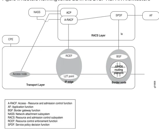
Networks (TISPAN)/IP multimedia subsystems (IMS) environment to provide VoIP functionality. IMS is a flexible network architecture that allows providers to introduce multimedia services across both next-generation packet-switched and traditional circuit-switched networks. It uses open interfaces and functional components that can be assembled flexibly to support real-time interactive services and applications. IMS provides a standards-based architecture that allows mobile carriers to migrate to next-generation networks that support applications that combine voice, video, and data functionality. The European Telecommunications Standards Institute (ETSI) created TISPAN to extend IMS support to fixed-line carriers. This extension is commonly called fixed mobile convergence (FMC). IMS/FMC allows subscribers to access any network (wireless or fixed) from any device (computer, PDA, or cell phone) and to move seamlessly from one network to another.
The router provides the BGF role, as shown in the ETSI-TISPAN architecture inFigure 1 on page 4:
Figure 1: Routers Running Junos OS in the ETSI-TISPAN Architecture
BGF VoIP Solution Terms and Abbreviations
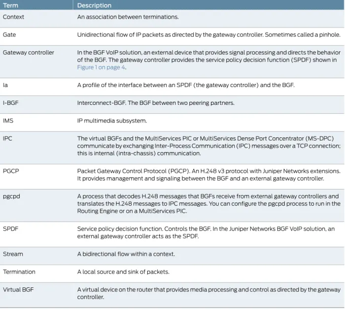
Table 3 on page 4defines the terms and abbreviations used in this topic.
Table 3: Terms and Abbreviations
Description Term
Table 3: Terms and Abbreviations
(continued)
Description Term
An association between terminations. Context
Unidirectional flow of IP packets as directed by the gateway controller. Sometimes called a pinhole. Gate
In the BGF VoIP solution, an external device that provides signal processing and directs the behavior of the BGF. The gateway controller provides the service policy decision function (SPDF) shown in
Figure 1 on page 4.
Gateway controller
A profile of the interface between an SPDF (the gateway controller) and the BGF. Ia
Interconnect-BGF. The BGF between two peering partners. I-BGF
IP multimedia subsystem. IMS
The virtual BGFs and the MultiServices PIC or MultiServices Dense Port Concentrator (MS-DPC) communicate by exchanging Inter-Process Communication (IPC) messages over a TCP connection; this is internal (intra-chassis) communication.
IPC
Packet Gateway Control Protocol (PGCP). An H.248 v3 protocol with Juniper Networks extensions. It provides management and signaling between the BGF and an external gateway controller. PGCP
A process that decodes H.248 messages that BGFs receive from external gateway controllers and translates the H.248 messages to IPC messages. You can configure the pgcpd process to run in the Routing Engine or on a MultiServices PIC.
pgcpd
Service policy decision function. Controls the BGF. In the Juniper Networks BGF VoIP solution, an external gateway controller acts as the SPDF.
SPDF
A bidirectional flow within a context. Stream
A local source and sink of packets. Termination
A virtual device on the router that provides media processing and control as directed by the gateway controller.
Virtual BGF
Supported Hardware Platforms for the BGF
Table 4 on page 5lists the hardware platforms that the BGF software supports. When we refer to services interfaces in the BGF documentation, we are referring to interfaces configured on the supported PIC, MS-DPC, or MIC.
Table 4: BGF Supported Hardware Platforms
PIC or Port Concentrator Supported Routing Platform
MultiServices 400 PIC MultiServices 500 PIC M120, M320
Table 4: BGF Supported Hardware Platforms
(continued)
PIC or Port Concentrator Supported Routing Platform
MultiServices Dense Port Concentrator (MS-DPC)
Trio Modular Port Concentrators (MPCs) with Modular Interface Cards (MICs) MX960, MX480, and MX240
MultiServices 500 PIC T640
MultiServices 100 PIC M7i, M10i
BGF VoIP Solution Architecture
This topic describes BGF architecture and its components. • BGF Architecture Diagram on page 6
• Gateway Controller on page 6 • BGF on page 7
• PGCP on page 7
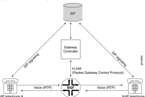
BGF Architecture Diagram
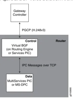
As shown inFigure 2 on page 6, the two main components of the voice solution are the BGF and the gateway controller. The BGF and the gateway controller communicate over the Packet Gateway Control Protocol (PGCP).
Figure 2: BGF Voice Solution Architecture
Gateway Controller
PGCP (H.248v3)
Router
g016990
MultiServices PIC or MS-DPC Virtual BGF (on Routing Engine
or Services PIC)
IPC Messages over TCP
Control
Data
Gateway Controller
from the BGF, and it uses those services and resources for VoIP call signaling setup. The gateway controller maintains awareness and control over the network’s transport resource using PGCP connections with all of the BGFs in the network.
BGF
The BGF feature on the router provides Interconnect-BGF transport services for VoIP sessions. The BGF feature consists of:
• Virtual BGFs.
• A pgcpd process that controls the virtual BGFs.
• A data PIC that controls voice traffic based on instructions it receives from the virtual BGFs. You can use MultiServices PICs or MS-DPCs as the data PIC.
• An optional control PIC. You can run the virtual BGFs with the pgcpd process on either the Routing Engine or on one or more PICs. If you run your virtual BGFs on control services PICs, you can use MultiServices PICs or MS-DPCs. The MultiServices 500 PIC is not supported as the control PIC.
You can run up to eight concurrent virtual BGFs on a control services PIC in a router. You can use up to four control services PICs, allowing you to scale up to a maximum of 32 concurrent virtual BGFs. All virtual BGFs on a router must run in either the Routing Engine or on services PICs. You cannot run some virtual BGFs on the Routing Engine and some on services PICs. When you choose the Routing Engine to run virtual BGFs, you are limited to a maximum of eight concurrent virtual BGFs.
PGCP
The BGF and the gateway controller communicate over a Packet Gateway Control Protocol (PGCP) connection. PGCP is an H.248 v3 protocol with Juniper Networks extensions. PGCP complies withGateway control protocol v3, ITU-T Recommendation H.248.1, September 2005and withH.248 Profile for controlling Border Gateway Functions, ETSI Standard ES 283 018 V1.1.4, October 2007.
BGF Topology with Multiple Virtual BGFs and Gateway Controllers Overview
This topic describes the use of multiple virtual BGFs and controllers in a routerYou can run up to eight concurrent virtual BGFs in a router when using the Routing Engine to run the virtual BGF. You can run up to 32 concurrent virtual BGFs when using control services PICs by assigning up to 8 virtual BGFs on each of 4 control services PICs.. Each virtual BGF is connected to a gateway controller over its own PGCP connection. One virtual BGF can connect to one gateway controller at the same time. Multiple virtual BGFs running in the Routing Engine or on the same control services PIC can share a single data service PIC. A single virtual BGF cannot span more than one data PIC or MS-DPC or more than one control PIC.
By creating multiple virtual BGFs, you can:
• Deploy different policy and quality-of-service (QoS) characteristics in your network. Chapter 1: BGF VoIP Solution Overview
• Scale your infrastructure by using multiple services PICs or MS-DPCs to control voice traffic.
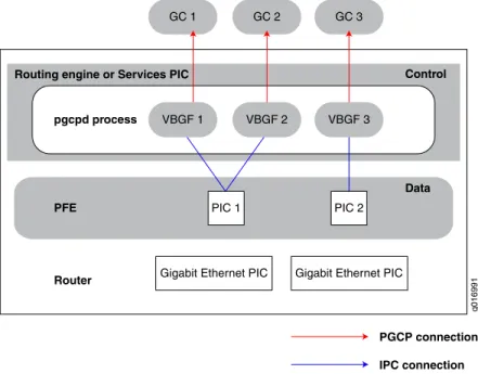
Figure 3 on page 8shows a topology with multiple virtual BGFs and gateway controllers. This topology enables one virtual BGF and one MultiServices PIC to continue handling gate requests and forwarding packets on open gates even when the other PIC fails.
Figure 3: Topology with Multiple Virtual BGFs and Gateway Controllers
PFE
GC 1 GC 2
Router pgcpd process Routing engine or Services PIC
g016991
VBGF 1 VBGF 2
PIC 1 PIC 2
Gigabit Ethernet PIC Gigabit Ethernet PIC
PGCP connection IPC connection
GC 3
VBGF 3
Control
Data
You can have multiple gateway controllers configured for one virtual BGF. When a virtual BGF begins running on the router, it attempts to set up a connection to the first configured gateway controller. Each virtual BGF can have one active gateway controller and one or more standby gateway controllers. In case of a gateway controller failure or in case of the gateway controller sending instructions to the virtual BGF, the virtual BGF can switch to another gateway controller.Figure 4 on page 9shows an active and standby gateway controller connected to virtual BGF 2.
Figure 4: Active and Standby Gateway Controllers
Router
pgcpd process
Routing engine or Services PIC
g016992
PGCP connection Standby PGCP connection IPC connection
GC 1 GC 2 GC 3
Active Standby
Standby
VBGF 1 VBGF 2
PIC 1 PIC 2
Control
Data Data
If the PGCP connection between the virtual BGF and the gateway controller is lost, the virtual BGF attempts to reconnect to the gateway controller. If the virtual BGF cannot reconnect to the gateway controller, it traverses its list of gateway controllers until it successfully connects to one of the gateway controllers.
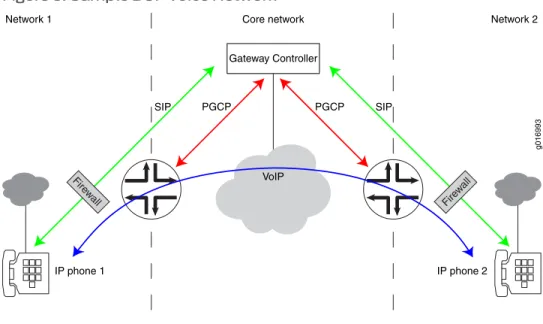
Sample BGF Voice Network Topology
Figure 5 on page 9shows an example of a network configuration using the BGF voice solution
Figure 5: Sample BGF Voice Network
IP phone 1 IP phone 2
VoIP
PGCP PGCP
SIP SIP
g016993
Network 1 Core network Network 2
Gateway Controller
Fire wall Fire
w all
Control of Voice Flows with Gates Overview
This topic describes how the virtual BGF controls voice flow with gates: • Using Gates for Voice Flows on page 10
• Gate Addressing on page 10
• Gate Opening, Closing, and Modification Overview on page 11 • Gate Identification on page 11
• Forward and Drop Operations for RTP and RTCP Gates on page 11 • Explicit and Implicit Latching on page 12
• Latch Deadlock and Media Inactivity Detection and Reporting on page 12
Using Gates for Voice Flows
The BGF uses gates to control voice flows in the transport plane. Gates are created through signaling instructions that the gateway controller provides to the BGF. Using the signaling instructions, the BGF defines gates to allow, drop, or manipulate voice flows as they traverse the router.
Each gate provides a unidirectional voice flow. A pair of gates provides a bidirectional voice flow.Figure 6 on page 10shows a unidirectional gate.
Figure 6: Unidirectional Gate
Gate Addressing
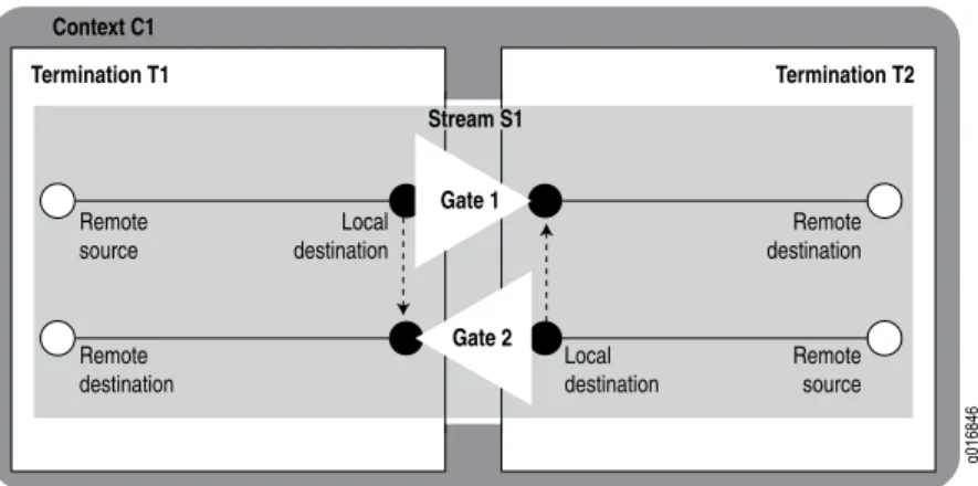
Gates are defined by their local source and destination addresses and their remote source and destination addresses.
Figure 7 on page 10shows a gate pair, which represents a bidirectional voice flow. The local destination address of Gate 1 is equal to the local source address of Gate 2, and the local source address of Gate 1 is equal to the local destination address of Gate 2.
Figure 7: Addressing of Gate Pairs
Gate Opening, Closing, and Modification Overview
Based on information acquired through VoIP signaling, the gateway controller instructs the BGF through H.248 commands which gates to create and which actions to associate with them. Each gate can have many actions associated with it; for example, NAT, Differentiated Services (DiffServ) code point (DSCP) marking, and latching. The pgcpd process decodes H.248 commands that it receives from the gateway controller and uses IPC messages to instruct the PIC or DPC to create, delete, or modify gates and apply required actions to each gate.
The following IPC messages are exchanged between the pgcpd process and the PIC or DPC:
• Gate open request • Gate close request • Gate audit request • Gate modify request • Gate open reply • Gate close reply • Gate audit reply • Gate modify reply • Gate notification reply
Gate Identification
When a gate is created, it is assigned an identifier. You can use this identifier with the show services pgcp gatescommands to monitor specific gates.
Forward and Drop Operations for RTP and RTCP Gates
You can use the StreamMode property in the LocalControl Descriptor of H.248 messages to change the mode of Realtime Transport Protocol (RTP) gates without affecting the mode of Real-Time Control Protocol (RTCP) gates. That is, you can put RTP gates in drop mode while leaving RTCP gates in forward mode.
To view whether RTP and RTCP gates are in drop mode or forward mode, use theshow services pgcp flowscommand. The following example shows a gate in which the RTP stream is in drop mode, and the RTCP stream is in forward mode.
user@host> show services pgcp flows gateway bgf-1
Gate id: 4295033089
UDP 20.50.170.110:0 -> 20.50.170.2:1024 Drop I 0 NAT source 20.50.170.110:0 -> 10.50.170.1:1024 NAT dest 20.50.170.2:1024 -> 10.50.170.110:20000 Gate id: 4295033089
UDP 20.50.170.110:0 -> 20.50.170.2:1025 Forward I 0 NAT source 20.50.170.110:0 -> 10.50.170.1:1025 NAT dest 20.50.170.2:1025 -> 10.50.170.110:20001
Explicit and Implicit Latching
By default, explicit latch requests cause latching of TCP gates. Implicit latching is available only for TCP gates. You can configure implicit latching of TCP gates by entering theset -latchandset -source-filterconfiguration statements at the[edit services pgcp gateway gateway-name h248-options]hierarchy level.
The configuration statements result in the following actions:
• -latch—If explicit latching has been applied (using ipnapt/latch) on either gate of a gate pair, implicit latching is not applied. If explicit latching has not been applied on either gate:
• Latching is applied to both gates of the gate pair.
• When either of the gates latches, latching is automatically disabled on the other gate.
• -source-filter—Applies source address (but not source port) filtering on incoming packets, using the current remote destination address under the following conditions: • Explicit source filtering has not been applied by use of gm/saf.
• Explicit latching has not been applied by use of ipnapt/latch.
Latch Deadlock and Media Inactivity Detection and Reporting
You can configure the parameters that a virtual BGF uses to detect and report latch deadlocks.
Detection
The virtual BGF uses an inactivity timer to detect a latch deadlock or other media inactivity on a gate. The timer tracks the receipt of media packets during a specified time interval. When a latching signal exists for a termination, the BGF places the termination in a Drop state. All incoming traffic to the relevant gate egressing the termination is dropped until the first IP traffic datagram enters the termination (ingress). At this point the remote descriptor on the termination and egress gate is updated to forward traffic to the newly acquired source. The latch signal is removed from the gate when the gateway controller receives an H.248 Notify message containing the newly acquired IP address. Deadlock occurs when an error occurs regarding the source IP address and port that prevents the endpoint from returning data to the source address.
The detection process is activated in one of the following ways: • The gateway controller requests quality (QUA) alerts.
• The gateway controller requests application data inactivity detection (ADID) alerts. • The CLI is used to configure a forced service change when media inactivity occurs.
The inactivity timer tracks the receipt of media packets during a specified interval of time (inactivity duration). If no media packets are received during this time interval, the virtual BGF reports the inactivity to the gateway controller.
Reporting
Reporting of the media inactivity occurs in one of the following ways:
• If the virtual BGF detects a latch deadlock or media inactivity and you have configured the virtual BGF to force a service change, the virtual BGF stops service on the gate and sends the gateway controller a ServiceChange message using either error code 906 (Loss of Lower Layer Connectivity) or 910 (Media Capability Failure). The virtual BGF then takes the affected termination out of service, but does not subtract the termination. • If you have not configured the virtual BGF to force a service change, the virtual BGF
sends a QUA or ADID notification message, depending on which type of notification was requested by the gateway controller.
Related Documentation
Configuring Implicit Latching for TCP Gates on page 44 •
• Configuring Latch Deadlock and Media Inactivity Detection on page 44 • Monitoring Gates on page 64
H.248 Building Blocks Overview
The topic describes the major H.248 building blocks used in the BGF voice solution. • H.248 Components on page 13
• Terminations on page 14 • Contexts on page 14 • Streams on page 14
H.248 Components
The H.248 connection model uses contexts, terminations, and streams, which are logical entities that the gateway controller controls. In the router, the MultiServices PIC or MS-DPC creates a context. The software then adds terminations to the context and adds streams to the terminations.Figure 8 on page 14shows a context, termination, and stream.
Figure 8: Context, Termination, and Stream
Terminations
A termination can be a source and sink for media and control streams, and the parameters of the streams are encapsulated within the termination. A termination is characterized by properties that are grouped in a set of descriptors that are included in add, subtract, modify, or audit commands. Terminations have unique identifiers (TerminationIDs) that the BGF assigns when it creates the termination.
Each termination is the source and destination of a gate. A termination exists only as long as a call. It is removed when the call is removed.
Contexts
A context is an association between a collection of terminations. The virtual BGF instructs a MultiServices PIC or MS-DPC to create a context for each voice session and each signaling session. Using instructions from the virtual BGF, the PIC or DPC then applies policies such as DSCP, NAT, rate limiting, and inactivity timers to the gates within a context. If the virtual BGF does not specify an existing context to which the termination is to be added, the PIC or DPC creates a new context.
Streams
A stream is one bidirectional flow within a context.
Virtual Interfaces with the BGF Overview
This topic describes the use of virtual interfaces with the BGF.
The BGF and the gateway controller communicate through virtual interfaces. Junos interface names are not known or communicated to the gateway controller. You configure a virtual interface on the BGF, and this virtual interface is provided to the gateway controller. The virtual interface configuration includes the media service for the virtual interface, which contains the name of the NAT pool.
Included in the H.248 message exchange between the gateway controller and the virtual BGF is a virtual interface identifier. This identifier instructs the BGF which media resources
Related Documentation
Configuring Virtual Interfaces on page 36 •
Twice NAT for VoIP Traffic Overview
This topic describes twice NAT functionality in the BGF voice solution. • Introduction to Twice NAT on page 15
• NAT Pool Selection on page 16
• IPv4-to-IPv6 Address Translation on page 17
Introduction to Twice NAT
The BGF supports both network address translation (NAT) and network address port translation (NAPT).Twice NATenables you to configure both source addresses and destination addresses that are translated as packets traverse the router. You can apply twice NAT for VoIP packets (signaling and media) as they traverse gates to achieve security between realms or service providers. To apply twice NAT, the pgcpd process instructs the PIC or DPC to allocate a specified number of NAT addresses and ports from a NAT pool on a per-gate basis. The pgcpd process specifies which NAT pool to use. Figure 9 on page 15shows two gates in a BGF.
Figure 9: Translation of Gate Addressing
After flows are created for Gate 1, the gate connects the remote source to the local destination. The local source and local destination addresses reside on the router and must be uniquely specified. For Gate 1, twice NAT enables the router to translate the IP address of the remote source to the local source, and the local destination to the remote destination.
To create the bidirectional flow, the same IP address is used for the local source in Gate 2 and the local destination in Gate 1. Likewise, the same IP address is used for the remote source in Gate 1 and the remote destination in Gate 2.
Figure 10 on page 16shows an example of how addresses are translated.
Figure 10: Example: Translation of Gate Addressing
NAT Pool Selection
You can configure separate NAT pools that can be controlled by either the BGF or the gateway controller. By default the BGF controls the addresses and ports in a pool. However, when you configure your NAT pool, you can specify that the gateway controller controls the addresses and ports in the NAT pool. The gateway controller reserves the addresses and ports when it requests specific local NAT bindings for remote addresses. If the BGF selects the NAT pool, it can use one of the following methods to select the pool:
• (Default) Using the value of the media services assigned to virtual interfaces configured on the BGF.
• Matching the transport protocol type in H.248 messages received from the gateway controller.
NAT Pool Selection by Matching the Transport Protocol
The BGF can select the NAT pool by matching any combination of the following protocols: • Real-Time Transport Protocol using audio/video profile (RTP/AVP)
• TCP • UDP
Selecting a NAT pool based on transport protocol:
• Guarantees the prioritized distribution of network resources. • Enables the use of multiple NAT pools for each virtual interface.
The gateway controller can set a transport protocol in the media description in the local descriptor command in add and modify commands that it sends to the BGF. The media description format is:
m=media port transport format list
where thetransportfield specifies the transport protocol. For example: m=video 49170/2 RTP/AVP 31
When you set up your NAT pools, you specify a transport protocol or list of protocols. Do not configure the NAT pool to be remotely controlled by the gateway controller. Also, set the port in the NAT pool to automatic.
When the BGF receives an add or modify command with a media description, it searches the NAT pools associated with the virtual interface and attempts to match the transport protocols in the description with the transport protocols specified in the NAT pools. The BGF uses the first NAT pool that has a matching transport protocol. If it cannot find a match, it replies to the gateway controller with the following error:
ER=500 {”Application: Media handler not found”}
IPv4-to-IPv6 Address Translation
IPv4-to-IPv6 address translation enables callers in an IPv4 network to place calls to recipients in an IPv6 network. With this capability, the access side of the network can be an IPv4 network and the backbone side of the network can be an IPv6 network and vice versa. The gateway controller sets up gates so that one termination of the gate has IPv4 addresses and the other termination of the gate has IPv6 addresses. The BGF performs the appropriate IPv4-to-IPv6 and IPv6-to-IPv4 translations.
This implementation is not the tunnelling of IPv4 headers over IPv6 headers and vice versa. It is the translation of the IPv4 headers to IPv6 headers and vice versa.
You must configure both an IPv4 NAT pool and an IPv6 NAT pool on the BGF for IPv4-to-IPv6 translation to work.
Figure 11 on page 17shows an example of a gate pair in a network where IPv4-to-IPv6 address translation is used.
Figure 11: IPv4-to-IPv6 Gates Using Twice NAT
Related Documentation
Configuring NAT Pools for the BGF on page 34 •
Quality of Service for VoIP Traffic Overview
This topic describes how to use DSCP code points to optimize service for VoIP traffic. To ensure optimized quality conditions for VoIP traffic, in gate open requests, the gateway controller can include a request for the BGF to mark voice traffic with various DSCP code points. The pgcpd process passes this information to the MultiServices PICs or MS-DPCs, which then apply these actions to the gate.
You can configure a default DSCP value that the virtual BGF uses for outgoing traffic when the DSCP value is not defined by the gateway controller. If you do not configure a value, the default value is 0x00. All eight bits are exposed, but the packet uses only the six leading bits. You can embed other data in the other two bits.
The DiffServ package is defined in Annex A.2 ofGateway control protocol v3, ITU-T Recommendation H.248.1, September 2005.
Related Documentation
Configuring QoS for the BGF on page 40 •
Rate-Limiting for VoIP Traffic Overview
This topic describes how use rate limiting to improve the flow of VoIP traffic. • Introduction to Rate Limiting on page 18
• How the Rate Limiting Feature Works on page 18 • Rate Limiting and Fast Update Filters on page 19 • Rate-Limiting Statistics Display on page 20
Introduction to Rate Limiting
Because BGF traffic flows involve voice traffic, the flows require quality of service that: • Provides the bandwidth that the flow requires.
• Ensures that flows do not consume more resources than they need.
• Regulates flows that are nonconforming and present vastly greater rates of traffic. The BGF provides a two-rate policer that you can apply to the ingress traffic of any gate. This quality of service is provided through a two-rate three-color policing functionality on the MultiServices PIC or MS-DPC. This policer complies withRFC 2698, A Two Rate Three Color Marker, September, 1999. With the rate limiting capability, the MultiServices PIC or MS-DPC can police flows to conform to:
• Committed information rate (CIR) • Peak information rate (PIR) • Committed burst size (CBS) • Peak burst size (PBS)
How the Rate Limiting Feature Works
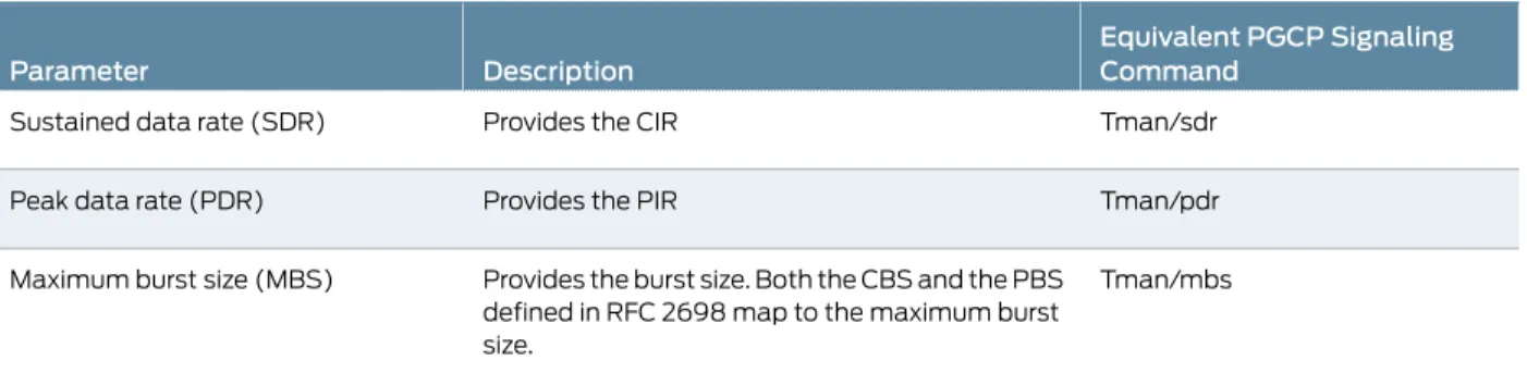
You use rate limiting with gates. To enable rate limiting for a gate, you need to provide traffic management package (TMAN) parameters. You can configure these parameters in the Junos OS CLI (Table 5 on page 19) or they can come from the H.248 signaling commands received from the gateway controller. Traffic management parameters that come from the gateway controller override parameters configured in the CLI.
Table 5: Traffic Parameters Configured in the CLI
Equivalent PGCP Signaling Command
Description Parameter
Tman/sdr Provides the CIR
Sustained data rate (SDR)
Tman/pdr Provides the PIR
Peak data rate (PDR)
Tman/mbs Provides the burst size. Both the CBS and the PBS
defined in RFC 2698 map to the maximum burst size.
Maximum burst size (MBS)
For each traffic management parameter, you can configure a value that applies to all gate streams and a value that applies only to RTCP gate streams. For RTCP streams, you can specify a fixed value for the parameters or you can specify the value as a percentage of the RTP rate. When RTP and RTCP are represented as a single stream, RTCP is policed whenever RTP is policed. You can also specify that RTCP bandwidth is be included in the SDR for streams other than RTCP.
The gateway controller can send traffic management parameters to the BGF in gate open and gate modify signaling requests. When the PIC or DPC receives these parameters, it marks the packets red, yellow, or green as specified in RFC 2698. A packet is marked: • Red if it exceeds the PIR.
• Yellow if it exceeds the CIR. • Green if it does not exceed the CIR.
Packets that are marked red are dropped by the PIC or DPC.
Default Values for Rate-Limiting Parameters
If the policy command H.248 message from the gateway controller is on (tman/pol=on), but the rate-limiting parameters are not specified in the message and the Junos rate-limiting parameters have not been configured, the BGF uses following default values: • Peak data rate—10,000 bytes per second for all streams and 5 percent of the RTP
gates’ PDR for RTCP streams.
• Sustained data rate—10,000 bytes per second for all streams and 5 percent of the RTP gate’s SDR for RTCP streams.
• Maximum burst size—1000 bytes for all streams and the MBS of the RTP gate for RTCP streams.
Rate Limiting and Fast Update Filters
When a VoIP flow configured through the BGF violates the SDR by three times the configured rate, fast update filters are installed on the gate to allow the rate-limiting drop action to occur on the PFE instead of the PIC or DPC.
A fast update filter is similar to a regular filter that is defined in the[edit firewall]hierarchy, except that the system can incrementally add or update terms.
For fast update filters, a term equals a gate definition. You can see gate definitions in the show services pgcp gates gatewaycommand output.
The fast update filter match is performed based on the most specific defined term. For each filter, a default term is installed to allow traffic to pass through (otherwise, all traffic is dropped because it is the default firewall action). For example, two terms are listed when there are two filters.
Filters are in effect until the gate is destroyed. If the client loses its connection for over 30 seconds, the existing filters are deleted, and default fast update filters are installed.
Rate-Limiting Statistics Display
To display statistics for a gate including rate-limiting statistics and the number of packets dropped because of FUF filters, use theshow services pgcp gate gatewaygateway-name gate-idgate-idstatisticscommand.
Related Documentation
Configuring Rate Limiting for the BGF on page 39 •
• Collecting Statistics on Gates with Rate-Limited Flows on page 69
Security for BGF Overview
The topic describes the security features available for the BGF.
• Protecting H.248 Messages and Mirrored Sessions with IPsec Overview on page 20 • Interim AH Scheme on page 21
• Symmetric Control Association on page 21
Protecting H.248 Messages and Mirrored Sessions with IPsec Overview
You can use IPsec authentication and encryption to protect H.248 messages and session mirroring call content (that is, the X3 interface).
The BGF supports IPsec tunnel and transport modes as follows:
• Tunnel mode—Use for H.248 messages and for session mirroring call content. You can use tunnel mode to protect H.248 messages whether you are running your virtual BGFs on the Routing Engine or on a services PIC or DPC.
• Transport mode—Use for H.248 messages when you are running your virtual BGFs on the Routing Engine. Transport mode is not supported on services PICs.
Related Documentation
Configuring IPsec to Protect H.248 Messages or Mirrored Sessions in Tunnel Mode on page 45
•
• Configuring IPsec to Protect H.248 Messages in Transport Mode on page 47Configuring IPsec to Protect H.248 Messages in Transport Mode on page 47