Outdoor Unit
Model name:
RAV-SM2244AT7
RAV-SM2804AT7
RAV-SM2244AT7Z
RAV-SM2804AT7Z
RAV-SM2244AT7ZG
RAV-SM2804AT7ZG
RAV-SM2244AT8-E
RAV-SM2804AT8-E
RAV-SM2244AT8Z-E
RAV-SM2804AT8Z-E
RAV-SM2244AT8ZG-E RAV-SM2804AT8ZG-E
Contents
1 ACCESSORY PARTS . . . 2
2 SAFETY PRECAUTIONS . . . 3
3 INSTALLATION OF NEW REFRIGERANT AIR CONDITIONER . . . 4
4 INSTALLATION CONDITIONS . . . 6
5 REFRIGERANT PIPING. . . 10
6 AIR PURGING . . . 14
7 ELECTRICAL WORK. . . 17
8 EARTHING . . . 19
9 FINISHING . . . 20
10 TEST RUN . . . 20
11 ANNUAL MAINTENANCE . . . 20
12 AIR CONDITIONER OPERATING CONDITIONS . . . 20
13 FUNCTIONS TO BE IMPLEMENTED LOCALLY . . . 21
14 TROUBLESHOOTING . . . 22
15 APPENDIX . . . 24
Please read this Installation Manual carefully before installing the Air Conditioner.• This Manual describes the installation method of the outdoor unit.
• For installation of the indoor unit, follow the Installation Manual attached to the indoor unit.
ADOPTION OF NEW REFRIGERANT
This Air Conditioner is a new type that has adopted a new refrigerant HFC (R410A) instead of the conventional refrigerant R22 in order to prevent destruction of the ozone layer.
This equipment complies with IEC 61000-3-12 provided that the short-circuit power Ssc is greater than or equal to Ssc (*1) at the interface point between the user’s supply and the public system. It is the responsibility of the installer or user of the equipment to ensure, by consultation with the distribution network operator if necessary, that the equipment is connected only to a supply with a short-circuit power Ssc greater than or equal to Ssc (*1).
Ssc (*1)
Model Ssc (MVA)
RAV-SM2244AT8(Z)(ZG)-E 1.41
1
ACCESSORY PARTS
Accessory Parts
INFORMATION
• The main pipe on the gas side of this outdoor unit has a diameter of Ø28.6 mm, but a Ø19.1 mm flare connection is used where the valve is connected. Be sure to use the Ø19.1 mm pipe and joint provided as accessories for the pipe connection. • Before installing the unit, check that the unit has the correct model name to prevent the wrong unit from being installed in the
wrong place.
• Before proceeding to weld the refrigerant pipe, be sure to pass nitrogen through the pipe.
• Before installing the indoor units, read the instructions in the installation manual provided with the indoor units. • Before installing a branch pipe, read the instructions in the installation manual provided with the branch pipe kit. • In the case of a simultaneous double twin system, use indoor unit with the same capacity for all four indoor units.
• P.C. board settings are required for some of the indoor units if they are to be used in a twin, triple or double twin system. Refer to the instructions in the installation manual of the branch pipe kit, and ensure that the settings are selected correctly. • Combination with the indoor units
Combination with the indoor units is possible only when units with the same type are combined. Combinations of units with different types cannot be used.
Part name Q’ty Shape Usage
Installation manual 1 (Hand this directly to the customer.)
Drain nipple 1
Waterproof rubber cap 1
Protective bush 1 For protecting wires (pipe cover)
Guard material for passage part 1 For protecting passage part (pipe cover)
Clamp filter 1 For conforming to EMC standards(Used for power wire)
Ø19.1 mm pipe 1 For the pipe inside the outdoor unit
Joint (Ø19.1 – Ø25.4 mm) 1 For connecting the pipe
Joint (Ø25.4 – Ø28.6 mm) 1 For connecting the pipe
Elbow 1 For connecting the pipe
Branch pipe kit Combination indoor unit
RAV-SM2244 RBC-DTWP101E SM56 × 4 units
2
SAFETY PRECAUTIONS
• Ensure that all Local, National and International regulations are satisfied. • Read these “SAFETY PRECAUTIONS” carefully before installation. • The precautions described below include important items regarding safety.
Observe them without fail.
• After the installation work, perform a trial operation to check for any problem.
Follow the Owner’s Manual to explain to the customer how to use and maintain the unit. • Ask the customer to keep the Installation Manual together with the Owner’s Manual.
WARNING
• Ask an authorized dealer or qualified installation professional to install/maintain the air conditioner. Perform installation work properly according to the Installation Manual.
Inappropriate installation may result in water leakage, electric shock or fire.
• Be sure to connect earth wire (grounding work).
Incomplete grounding cause an electric shock.
Do not connect ground wires to gas pipes, water pipes, lightning rods or ground wires for telephone wires.
• Turn off the main power supply switch or breaker before attempting any electrical work and maintenance.
Make sure all power switches are off. Failure to do so may cause electric shock. Use an exclusive power circuit for the air conditioner. Use the rated voltage.
• Connect the connecting wire correctly.
If the connecting wire is incorrect, electric parts may be damaged.
• When moving the air conditioner for installation to another place, be very careful not to allow the specified
refrigerant (R410A) to become mixed with any other gaseous body into the refrigeration cycle.
If air or any other gas mixes with the refrigerant, the gas pressure in the refrigeration cycle will become abnormally high and it may result in the pipe bursting or personal injuries.
• Do not modify this unit by removing any of the safety guards or by by-passing any of the safety interlock switches.
• Do not touch the intake or aluminum fins of the outdoor unit.
Doing so may result in injury.
• Tighten the flare nut with a torque wrench in the specified manner.
Excessive tightening of the flare nut may cause a crack in the flare nut after a long period, which may result in refrigerant leakage.
• Install the air conditioner securely in a location where the base can sustain the weight of the unit adequately.
• Perform the specified installation work to guard against an earthquake.
If the air conditioner is not installed appropriately, accidents may occur due to the unit falling.
• If refrigerant gas has leaked during the installation work, ventilate the room immediately.
If the leaked refrigerant gas comes in contact with fire, noxious gas may be generated.
• After the installation work, confirm that refrigerant gas does not leak.
If refrigerant gas leaks into the room and flows near a fire source, such as a cooking range, noxious gas may be generated.
• Electrical work must be performed by a qualified electrician in accordance with the Installation Manual. Make sure
the air conditioner uses an exclusive power supply.
An insufficient power supply capacity or inappropriate installation may cause fire.
• Use only the specified wiring during the unit installation. Ensure that all terminals are securely fixed, so preventing any external forces having a negative effect on the terminals.
• When the air conditioner cannot cool or heat a room well, contact the dealer from whom you purchased the air
conditioner as refrigerant leakage is considered as the cause.
In the case of repair that requires refill of refrigerant, ask service personnel about details of the repair.
The refrigerant used in the air conditioner is harmless.
Generally, the refrigerant does not leak. However, if the refrigerant leaks in a room and a heater or stove burner in the room catches fire, it may generate toxic gas.
When you ask service personnel for repairing refrigerant leakage, confirm that the leakage portion has been completely repaired.
• Conform to the regulations of the local electric company when wiring the power supply.
Inappropriate grounding may cause electric shock.
• Do not install the air conditioner in a location that may be subjected to a risk of exposure to a combustible gas.
• Install the refrigerant pipe securely during the installation work before operating the air conditioner.
If the compressor is operated with the valve open and without the refrigerant pipe, the compressor sucks air and the refrigeration cycle is overpressurized, which may cause a burst or injury.
• When carrying out the pump-down work, shut down the compressor before disconnecting the refrigerant pipe.
Disconnecting the refrigerant pipe with the service valve left open and with the compressor still operating will cause air, etc. to be sucked in, raising the pressure inside the refrigeration cycle to an abnormally high level, and possibly resulting in rupturing, injury, etc.
CAUTION
• Do not climb onto or place objects on top of the outdoor unit.
You may fall or the objects may fall off of the outdoor unit and result in injury.
• Wear heavy gloves during the installation work to avoid injury.
To Disconnect the Appliance from the Main Power Supply
• This appliance must be connected to the main power supply by means of a switch with a contact separation of at least 3 mm. • A 25 A installation fuse (all fuse types can be used) must be used for the power supply line of this conditioner.
3
INSTALLATION OF NEW REFRIGERANT AIR
CONDITIONER
CAUTION
New Refrigerant Air Conditioner Installation
• THIS AIR CONDITIONER ADOPTS THE NEW HFC REFRIGERANT (R410A) WHICH DOES NOT DESTROY OZONE
LAYER.
R410A refrigerant is apt to be affected by impurities such as water, oxidizing membrane, and oils because the working pressure of R410A refrigerant is approx. 1.6 times as that of refrigerant R22. Accompanied with the adoption of the new refrigerant, the refrigerant oil has also been changed. Therefore, during installation work, be sure that water, dust, former refrigerant, or refrigerant oil does not enter the new type refrigerant R410A air conditioner cycle.
To prevent mixing of refrigerant or refrigerant oil, the sizes of connecting sections of charging port on main unit and installation tools are different from those of the conventional refrigerant units. Accordingly, special tools are required for the new refrigerant (R410A) units. For connecting pipes, use new and clean piping materials with high pressure fittings made for R410A only, so that water and/or dust does not enter.
Required Tools/Equipment and Precautions for Use
Prepare the tools and equipment listed in the following table before starting the installation work. Newly prepared tools and equipment must be used exclusively.
Legend
: Prepared newly (Use for R410A only. Do not use for refrigerant R22 or R407C etc.) : Conventional tools/equipment are available
Refrigerant Piping
New refrigerant (R410A)
When using the conventional piping
• When using the conventional piping with no indication of applicable refrigerant types, be sure to use it with a wall thickness of 0.8 mm for Ø6.4 mm, Ø9.5 mm, and Ø12.7 mm, with a wall thickness of 1.0 mm for Ø15.9 mm, with a wall thickness of 1.2 mm for Ø19.1 mm, and with a wall thickness of 1.0 mm for Ø28.6 mm (half hard). Do not use the conventional piping with a wall thickness less than these thicknesses due to insufficient pressure capacity.
When using general copper pipes
• Use general copper pipes with a wall thickness of 0.8 mm for Ø6.4 mm, Ø9.5 mm, and Ø12.7 mm, with a wall thickness of 1.0 mm for Ø15.9 mm, with a wall thickness of 1.2 mm for Ø19.1 mm, and with a wall thickness of 1.0 mm for Ø28.6 mm (half hard).
Do not use any copper pipes with a wall thickness less than these thicknesses.
Flare nuts and flare machining
• The flare nuts and flare machining are different from those for the conventional refrigerant. Use the flare nuts supplied with the air conditioner or those for R410A.
• Before performing flare machining, carefully read “REFRIGERANT PIPING”.
Tools/equipment Use How to use tools/equipment
Gauge manifold Vacuuming/charging refrigerant
and operation check
Prepared newly for R410A only
Charging hose Prepared newly for R410A only
Charging cylinder Can not be used Unusable (Use the refrigerant charging measure instead.)
Gas leak detector Gas leak check Prepared newly
Vacuum pump Vacuum drying Unusable
Vacuum pump with backflow
prevention function Vacuum drying R22 (Conventional tools)
Flare tool Flare machining of pipes Usable if dimensions are adjusted.
Bender Bending pipes R22 (Conventional tools)
Refrigerant recovery equipment Refrigerant recovery For R410A only
Torque wrench Tightening flare nuts Exclusive for Ø12.7 mm and Ø19.1 mm
Pipe cutter Cutting pipes R22 (Conventional tools)
Welding machine and nitrogen
cylinder Welding pipes R22 (Conventional tools)
4
INSTALLATION CONDITIONS
Before installation
Be sure to prepare to the following items before installation.
Length of refrigerant pipe
* If the total length of the refrigerant pipe exceeds 30 m, add refrigerant in the amount given in the “Adding additional refrigerant”.
* Do not connect a refrigerant pipe that is shorter than
7.5 m.
This may cause a malfunction of the compressor or other devices.
Airtight test
1. Before starting an airtight test, further tighten the spindle valves on the gas and liquid sides.
2. Pressurize the pipe with nitrogen gas charged from the service port to the design pressure (4.15 MPa) to conduct an airtight test.
3. After the airtight test is completed, evacuate the nitrogen gas.
Air purge
• To purge air, use a vacuum pump.
• Do not use refrigerant charged in the outdoor unit to purge air. (The air purge refrigerant is not contained in the outdoor unit.)
Electrical wiring
• Be sure to fix the power wires and indoor/outdoor connecting wires with clamps so that they do not come into contact with the cabinet, etc.
Earthing WARNING
Make sure that proper earthing is provided.
Improper earthing may cause an electric shock. For details on how to check earthing, contact the dealer who installed the air conditioner or a professional installation company.
• Proper earthing can prevent charging of electricity on the outdoor unit surface due to the presence of a high frequency in the frequency converter (inverter) of the outdoor unit, as well as prevent electric shock. If the outdoor unit is not properly earthed, you may be exposed to an electric shock.
• Be sure to connect the earth wire (grounding work).
Incomplete grounding can cause an electric shock. Do not connect ground wires to gas pipes, water pipes, lightning rods or ground wires for telephone wires.
Test Run
Turn on the leakage breaker at least 12 hours before starting a test run to protect the compressor during startup.
CAUTION
Incorrect installation work may result in a malfunction or complaints from customers.
Length of refrigerant pipe connected to indoor/
outdoor unit
Item
7.5 to 30 m Addition of refrigerant is unnecessary at the local site.
*31 to 70 m
<Addition of refrigerant> Add 40 g of refrigerant for every 1 m of piping that exceeds 30 m.
Installation Location
WARNING
Install the outdoor unit properly in a location that is durable enough to support the weight of the outdoor unit.
Insufficient durability may cause the outdoor unit to fall, which may result in injury.
This outdoor unit has a weight of about 135 kg. Pay special attention when installing the unit onto a wall surface.
CAUTION
Do not install the outdoor unit in a location that is subject to combustible gas leaks.
Accumulation of combustible gas around the outdoor unit may cause a fire.
Install the outdoor unit in a location that meets the following conditions after the customer’s consent is obtained.
• A well-ventilated location free from obstacles near the air inlets and air outlet
• A location that is not exposed to rain or direct sunlight • A location that does not increase the operating noise or
vibration of the outdoor unit
• A location that does not produce any drainage problems from discharged water
Do not install the outdoor unit in the following locations.
• A location with a saline atmosphere (coastal area) or one that is full of sulfide gas (hot-spring area) (Special maintenance is required.)
• A location subject to oil, vapor, oily smoke, or corrosive gases
• A location in which organic solvent is used
• A location where high-frequency equipment (including inverter equipment, private power generator, medical equipment, and communication equipment) is used (Installation in such a location may cause malfunction of the air conditioner, abnormal control or problems due to noise from such equipment.)
• A location in which the discharged air of the outdoor unit blows against the window of a neighboring house • A location where the operating noise of the outdoor unit is
transmitted
• When the outdoor unit is installed in an elevated position, be sure to secure its feet.
• A location in which drain water poses any problems.
CAUTION
1. Install the outdoor unit in a location where the discharge air is not blocked.
2. When an outdoor unit is installed in a location that is always exposed to strong winds like a coast or on the high stories of a building, secure normal fan operation by using a duct or wind shield.
3. When installing the outdoor unit in a location that is constantly exposed to strong winds such as on the upper stairs or rooftop of a building, apply the windproofing measures referred to in the following examples. 1) Install the unit so that its discharge port faces the
wall of the building.
Keep a distance 500 mm or more between the unit and wall surface.
2) Consider the wind direction during the operational season of the air conditioner, and install the unit so that the discharge port is set at a right angle relative to the wind direction.
• When using an air conditioner under low outside temperature conditions (Outside temp:-5 °C or lower) in COOL mode, prepare a duct or wind shield so that it is not affected by the wind.
500 mm
Strong wind
Strong wind
<Example>
Wind shield
Necessary Space for Installation
(Unit: mm)
Obstacle at rear side
Upper side is free
1. Single unit installation
2. Obstacles on both right and left sides
3. Serial installation of two or more units
Obstacle also above unit
Obstacle in front
Above unit is free
1. Single unit installation
2. Serial installation of two or more units
Obstacle also at the above unit
Obstacles in both front and rear of unit
Open above and to the right and left of the unit.
The height of an obstacle in both the front and rear of the unit, should be lower than the height of the outdoor unit.
Standard installation
1. Single unit installation
2. Serial installation of two or more units
150
or
mo
re
200 or mor
e
150 or
more 250 or more
The height of the obstacle should be lower than the height of the outdoor unit.
150 or
more 250 or more 250 or more 250 or more The height of the obstacle should be lower than the height of the outdoor unit.
200 or mor
e
150 or more
50
0 o
r
more
500 or mo
re
1,
00
0 o
r
mor
e
80
0 or
more
1,000 or more
150
or
mo
re
1,
000 o
r
more
200 or mor
e
1,
000
or
more
250 or
Serial installation in front and rear
Open above and to the right and left of the unit.
The height of an obstacle in both the front and rear of the unit should be lower than the height of the outdoor unit.
Standard installation
Installation of Outdoor Unit
• Before installation, check the strength and horizontalness of the base so that abnormal sounds do not emanate. • According to the following base diagram, fix the base
firmly with the anchor bolts. (Anchor bolt, nut: M10 x 4 pairs)
• As shown in the figure below, install the foundation and vibration-proof rubber pads to directly support the bottom surface of the fixing leg that is in contact with and underneath the bottom plate of the outdoor unit. * When installing the foundation for an outdoor unit with
downward piping, consider the piping work.
Set the out margin of the anchor bolt to 15 mm or less.
• When water is to be drained through the drain hose, attach the following drain nipple and waterproof rubber cap, and use the drain hose (Inner diam: 16 mm) sold on the market. Also seal the knockout hole and screws securely with silicone material, etc., to prevent water from leaking.
Some conditions may cause dewing or dripping of water. • When collectively draining discharged water completely,
use a drain pan.
• Please pay attention to the drain in region with snowfall and cold temperature, as it may be frozen and cause drainage problems. Punch the knockout holes on the base plate to improve drainability. Use a screwdriver and take off the knockout part outward.
For Reference
If a heating operation is to be continuously performed for a long time under the condition that the outdoor temperature is 0 °C or lower, draining defrosted water may be difficult due to the bottom plate freezing, resulting in trouble with the cabinet or fan.
It is recommended to procure an anti-freeze heater locally in order to safely install the air conditioner.
1,000 or
more 300 or more 1,500 or more 2,000 or more 200 or more
150 600 150
430
40
365
400
Drain nipple mounting hole Drain hole
Knockout hole
GOOD
Fixing leg
Absorb vibration with vibration-proof
rubber pads
Foundation
GOOD
Bottom plate of outdoor unit
Foundation
Support the bottom surface of the fixing leg that is in contact with and underneath the bottom plate of the
outdoor unit.
NO GOOD If only the end of the
fixing leg is supported, it may deform.
Do not support the outdoor unit only with the fixing leg.
Foundation
15 or less
Drain nipple
Waterproof rubber cap (5 pcs.)
Waterproof rubber cap Drain nipple
5
REFRIGERANT PIPING
Knockout of Pipe Cover
Knockout procedure
• The indoor/outdoor connecting pipes can be connected in 4 directions.
Take off the knockout part of the pipe cover through which pipes or wires will pass through the base plate. • Detach the pipe cover and tap on the knockout section a
few times with the shank of a screwdriver. A knockout hole can easily be punched.
• As shown in the figure below, it is easier to punch out the knockout hole when the pipe cover is left in place rather than when the cover is removed from the unit.
In knocking out the hole, the knockout section can easily be removed by hand once the bottom of the three locations where the section is joined along the guide lines is broken using a screwdriver.
• After punching out the knockout hole, remove burrs from the hole, and install the protective bush and guard material around the passage hole provided as
accessories in order to protect the wires and pipes. Also be sure to attach the pipe covers after connecting the pipes. The pipe covers can be easily attached by cutting off the slits at the lower part of the covers.
* Be sure to wear heavy work gloves while working.
Optional Installation Parts
(Locally procured)
REQUIREMENT
Follow the instructions in the installation manual provided with the branch pipe kit and the instructions in the installation manual of the indoor unit to connect the refrigerant pipe between the branch pipe and indoor unit.
Refrigerant Piping Connection
CAUTION
TAKE NOTE OF THESE 4 IMPORTANT POINTS BELOW FOR PIPING WORK
1. Keep dust and moisture away from inside the connecting pipes.
2. Tightly connect the connection between pipes and the unit.
3. Evacuate the air in the connecting pipes using a VACUUM PUMP.
4. Check for gas leaks at connection points.
Piping connection
REQUIREMENT
On the gas side, be sure to use the Ø19.1 mm pipe provided with the outdoor unit.
Rear direction
Pipe cover Side direction
Down direction Front direction
Parts name Q’ty
A
Refrigerant piping Liquid side: Ø12.7 mm
Gas side: Ø19.1 mm (Approx. 800 mm) Ø28.6 mm
One each
B Pipe insulating material
(polyethylene foam, 10 mm thick) 1
C Putty, PVC tape One each
Liquid side
Outer diameter Thickness
Ø12.7 mm 0.8 mm
Gas side
Outer diameter Thickness
Ø19.1 mm 1.2 mm
Flaring
1. Cut the pipe with a pipe cutter.
Be sure to remove burrs that may cause a gas leak. 2. Insert a flare nut into the pipe, and then flare the pipe.
Use the flare nuts supplied with the air conditioner or those for R410A.
Insert a flare nut into the pipe, and flare the pipe. As the flaring sizes of R410A differ from those of refrigerant R22, the flare tools newly manufactured for R410A are recommended.
However, the conventional tools can be used by adjusting the projection margin of the copper pipe.
Projection margin in flaring: B (Unit: mm)
Rigid (Clutch type)
Flaring diameter size: A (Unit: mm)
* In case of flaring for R410A with the conventional flare tool, pull the tool out approx. 0.5 mm more than that for R22 to adjust it to the specified flare size.
The copper pipe gauge is useful for adjusting the projection margin size.
Connecting the Gas Side Pipe
REQUIREMENT
• Be sure to use the Ø19.1 mm pipe and joint provided as accessories of the outdoor unit to connect the gas side Ø19.1 mm pipe and Ø28.6 mm pipe.
• When leading out the pipes toward the front, to one of the sides or toward the rear, use the Ø19.1 mm pipe and elbow provided as accessories of the outdoor unit, and adjust the bending direction. Cut the Ø19.1 mm pipe to the required length before using it.
1. Align the provided Ø19.1 mm pipe with the pipe lead-out direction, and shape it so that its end comes out from the outdoor unit.
2. On the outside of the outdoor unit, use the provided joints, and braze the Ø19.1 mm pipe and Ø28.6 mm pipe.
REQUIREMENT
• Before proceeding to weld the refrigerant pipe, be sure to pass nitrogen through the pipe to prevent oxidation inside it. If nitrogen is not passed through the pipe, the
refrigerating cycle may become clogged by oxidized scales.
• The Ø28.6 mm pipe cannot be passed through the pipe cover and knockout hole in the base plate so be sure to connect the Ø19.1 mm pipe and Ø28.6 mm pipe outside
Outer diam. of copper pipe
R410A tool used Conventional tool
used R410A
1.0 to 1.5 9.5
0 to 0.5 12.7
15.9 19.1
Outer diam. of copper pipe A
9.5 13.2
12.7 16.6
15.9 19.7
19.1 24.0
B
A
+0 –0.4
Ø19.1 mm pipe (accessory)
Ø19.1 mm pipe
(accessory) Brazing
Elbow (accessory) Ø19.1 mm pipe (accessory)
Ø19.1 mm pipe (accessory)
Ø28.6 mm pipe (procured locally) Joint
(accessory)
Joint (accessory)
Tightening of Connecting Part
1. Align the centers of the connecting pipes and fully tighten the flare nut with your fingers. Then fix the nut with a wrench as shown in the figure and tighten it with a torque wrench.
2. As shown in the figure, be sure to use two wrenches to loosen or tighten the flare nut of the valve on the gas side. If you use a single crescent, the flare nut cannot be tightened to the required tightening torque.
On the other hand, use a single crescent to loosen or tighten the flare nut of the valve on the liquid side.
(Unit: N•m)
CAUTION
1. Do not put the crescent wrench on the cap or cover. The valve may break.
2. If applying excessive torque, the nut may break according to some installation conditions.
• After the installation work, be sure to check for gas leaks of the pipe connections with nitrogen.
• Pressure of R410A is higher than that of R22 (Approx. 1.6 times).
Therefore, using a torque wrench, tighten the flare pipe connecting sections that connect the indoor/outdoor units at the specified tightening torque.
Incomplete connections may cause not only a gas leak, but also trouble with the refrigeration cycle.
Branch Pipe
Carry out the refrigerant piping work using the branch pipe kit which is purchased separately.
Branch pipe installation
Length of straight sections on main pipe side of branch pipe
Provide a straight section with a length of at least 500 mm on the main pipe side of the branch pipe. (Same for both liquid side and gas side)
Outer dia. of copper pipe Tightening torque
9.5 mm (diam.) 33 to 42 (3.3 to 4.2 kgf•m) 12.7 mm (diam.) 50 to 62 (5.0 to 6.2 kgf•m) 15.9 mm (diam.) 68 to 82 (6.8 to 8.2 kgf•m) 19.1 mm (diam.) 100 to 120 (10.0 to 12 kgf•m)
Half union or packed valve Flare nut
Externally
threaded side Internally threaded side
Fix with wrench. Tighten with torque wrench.
Cover
Piping valve Tightened
Flare nut Cap
Loosened
Valve at gas side
NO GOOD
Cover
Cap
Do not apply refrigerant oil to the flared surface.
The ends of the branch pipes form a line perpendicular to the ground.
Both the collecting pipe and branch pipes form a line parallel to the ground.
Collection area Collecting pipe
Branch pipe
Make sure that the pipes are installed level after branching. Inclined
The ends of the branch pipes form a line
perpendicular to the ground.
Both the collecting pipe and branch pipes form a line parallel to the ground.
Branch pipe
Liquid side Gas side
NO GOOD
500 mm or more
500 mm or more
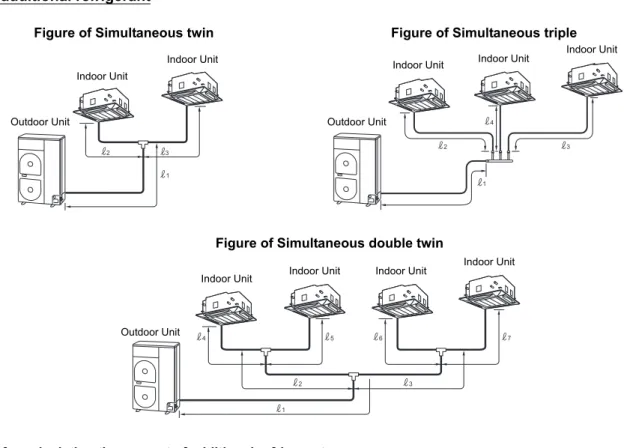
Refrigerant Pipe Length
Simultaneous twin, triple
Simultaneous double twin
Outdoor unit
Allowable pipe length (m) Height difference (m)
Total length
• 1 + 2
• 1 + 3
• 1 + 4
Maximum Branch piping • 2 • 3 • 4 Maximum Branch piping
• 3 – 2
• 4 – 2
• 4 – 3
Maximum
Indoor-outdoor H
Indoor-indoor (Δh) Indoor unit:
Upper Outdoor unit: Upper
SM2244 70 20 10 30 30 0.5
SM2804 70 20 10 30 30 0.5
Outdoor unit
Pipe diameter (mm)
Number of bent portions
Main pipe Branch piping
Gas side Liquid side Gas side Liquid side
SM2244 Ø28.6 Ø12.7 Ø15.9 Ø9.5 10 or less
SM2804 Ø28.6 Ø12.7 Ø15.9 Ø9.5 10 or less
Outdoor unit
Allowable pipe length (m) Height difference (m)
Total length
• 1 + 2 + 4
• 1 + 2 + 5
• 1 + 3 + 6
• 1 + 3 + 7
Maximum Branch piping • 4 • 5 • 6 • 7 Maximum Branch piping
• 4 + 2
• 5 + 2
• 6 + 3
• 7 + 3
Maximum
Branch piping • ( 4 + 2) – ( 5 + 2) • ( 4 + 2) – ( 6 + 3) • ( 4 + 2) – ( 7 + 3) • ( 5 + 2) – ( 6 + 3) • ( 5 + 2) – ( 7 + 3) • ( 6 + 3) – ( 7 + 3) Maximum
Indoor-outdoor H
Indoor-indoor (Δh) Indoor unit: Upper Outdoor unit: Upper
SM2244 70 15 20 6 30 30 0.5
SM2804 70 15 20 6 30 30 0.5
Outdoor unit
Pipe diameter (mm)
Number of bent portions
Main pipe Branch piping
Gas side Liquid side Gas side Liquid side
SM2244 Ø28.6 Ø12.7 2, 3: Ø15.9
4, 5, 6, 7: Ø12.7
2, 3: Ø9.5
4, 5, 6, 7: Ø6.4 10 or less
SM2804 Ø28.6 Ø12.7 2 to 7: Ø15.9 2 to 7: Ø9.5 10 or less
3 2
4
1
H
2 3 H 1
Figure of Simultaneous twin Indoor Unit Indoor Unit Outdoor Unit Indoor Unit Indoor Unit Outdoor Unit Indoor Unit Figure of Simultaneous triple
Figure of Simultaneous double twin Indoor Unit
Indoor Unit
Outdoor Unit
6
AIR PURGING
Airtight Test
Before starting an airtight test, further tighten the spindle valves on the gas side and liquid side.
Pressurize the pipe with nitrogen gas charged from the service port to the design pressure (4.15 MPa) to conduct the airtight test.
After the airtight test is completed, evacuate the nitrogen gas.
Air Purge
With respect to the preservation of the terrestrial
environment, adopt “Vacuum pump” to purge air (Evacuate air in the connecting pipes) when installing the unit.
• Do not discharge the refrigerant gas to the atmosphere to preserve the terrestrial environment.
• Use a vacuum pump to discharge the air (nitrogen, etc.) that remains in the set. If air remains, the capacity may decrease.
For the vacuum pump, be sure to use one with a backflow preventer so that the oil in the pump does not backflow into the pipe of the air conditioner when the pump stops. (If oil in the vacuum pump is put in an air conditioner including R410A, it may cause trouble with the refrigeration cycle.)
Vacuum pump
*1 Use the vacuum pump, vacuum pump adapter, and gauge
manifold correctly referring to the manuals supplied with each tool before using them.
Check that the vacuum pump oil is filled up to the specified line of the oil gauge.
*2 When air is not charged, check again whether the connecting
port of the discharge hose, which has a projection to push the valve core, is firmly connected to the charge port.
Pressure gauge Gauge manifold valve
Handle High (Keep fully closed) Compound pressure gauge
Charge hose (For R410A only)
Vacuum pump adapter for counter-flow prevention (For R410A only) –101 kPa
(–76 cmHg) Handle Low Charge hose (For R410A only)
Charge port
(Valve core (Setting pin))
Packed valve at gas side Vacuum
pump
As shown in the figure, connect the charge hose after the manifold valve is closed completely.
L
Attach the connecting port of the charge hose with a projection to push the valve core (setting pin) to the charge
port of the set.
L
Open Handle Low fully.
L
Turn ON the vacuum pump. (*1)
L
Loosen the flare nut of the packed valve (Gas side) a little to check that the air passes through. (*2)
L
Retighten the flare nut.
L
Execute vacuuming until the compound pressure gauge indicates –101 kPa (–76 cmHg). (*1)
L
Close Handle Low completely.
L
Turn OFF the vacuum pump.
L
Leave the vacuum pump as it is for 1 or 2 minutes, and check that the indicator of the compound pressure gauge
does not return.
L
Open the valve stem or valve handle fully. (First, at liquid side, then gas side)
L
Disconnect the charge hose from the charge port.
L
How to Open the Valve
Open or close the valve.Liquid side
Open the valve with a 4 mm hexagon wrench.
Gas side
• While the valve is fully opened, after the screwdriver has reached the stopper, do not apply torque exceeding 5 N•m. Applying excessive torque may damage the valve.
Valve handling precautions
• Open the valve stem until it strikes the stopper. It is unnecessary to apply further force. • Securely tighten the cap with a torque wrench.
Cap tightening torque
Insulating the Pipes
• The temperatures at both the liquid side and gas side will be low during cooling so in order to prevent
condensation, be sure to insulate the pipes at both of these sides.
• Insulate the pipes separately for the liquid side and gas side.
• Insulate the branch pipes by following the instructions in the installation manual provided with the branch pipe kit. • Use the insulating material provided as an accessory to
insulate the Ø19.1 mm pipe at the gas side.
• Seal the area where the Ø19.1 mm pipe and Ø22.2 to Ø28.6 mm pipe are connected so that no gaps are left.
REQUIREMENT
Be sure to use an insulating material which can withstand temperatures above 120°C for the gas side pipe since this pipe will become very hot during heating operations.
Replenishing Refrigerant
This model is a 30 m chargeless type that does not need to have its refrigerant replenished for refrigerant pipes up to 30 m. When a refrigerant pipe longer than 30 m is used, add the specified amount of refrigerant.
Refrigerant replenishing procedure
1. After vacuuming the refrigerant pipe, close the valves and then charge the refrigerant while the air conditioner is not working.
2. When the refrigerant cannot be charged to the specified amount, charge the required amount of refrigerant from the charge port of the valve on the gas side during cooling.
Requirement for replenishing refrigerant
Replenish liquid refrigerant.
When gaseous refrigerant is replenished, the refrigerant composition varies, which disables normal operation.
Valve size
Ø12.7 mm 50 to 62 N•m(5.0 to 6.2 kgf•m) Ø19.1 mm 20 to 25 N•m(2.0 to 2.5 kgf•m) Charge port 14 to 18 N•m(1.4 to 1.8 kgf•m)
Valve unit
Charge port
Using a minus screwdriver, turn it counterclockwise by 90° until it hits the stopper. (Full open)
Flare nut
Handle position
Closed completely Opened fully
Main stopper Movable part of valve (Stem) Stopper pin
Adding additional refrigerant
Formula for calculating the amount of additional refrigerant
(Formula will differ depending on the diameter of the liquid connecting side pipe.) * 1 to 7 are the lengths of the pipes shown in the figures above (unit: m).
Simultaneous twin
Simultaneous triple
Simultaneous double twin Diameter of connecting pipe
(liquid side)
Amount of additional refrigerant per meter
(g/m)
Amount of additional refrigerant (g) = Amount of refrigerant added for main pipe + amount of refrigerant added for branch piping
1 2 3 α β
Ø12.7 Ø9.5 Ø9.5 80 40 α × ( 1 – 28) + β × ( 2 + 3 – 4)
Diameter of connecting pipe (liquid side)
Amount of additional refrigerant per meter
(g/m)
Amount of additional refrigerant (g) = Amount of refrigerant added for main pipe +
amount of refrigerant added for branch piping
1 2 3 4 α β
Ø12.7 Ø9.5 Ø9.5 Ø9.5 80 40 α × ( 1 – 28) + β × ( 2 + 3 + 4 – 6)
Outdoor unit
Diameter of connecting pipe (liquid side)
Amount of additional refrigerant per meter (g/m)
Amount of additional refrigerant (g) = Amount of refrigerant added for main pipe
+ amount of refrigerant added for first branch piping + amount of refrigerant
added for second branch piping
1 2, 3 4 to 7 α β γ
SM2244 Ø12.7 Ø9.5 Ø6.4 80 40 20 α × ( 1 – 28) + β × ( 2 + 3 – 4) + γ × ( 4 + 5 + 6 + 7)
SM2804 Ø12.7 Ø9.5 Ø9.5 80 40 40 α × ( 1 – 28) + β × ( 2 + 3 – 4) + γ × ( 4 + 5 + 6 + 7)
3 2
4
1 2 3
1
Figure of Simultaneous twin Indoor Unit Indoor Unit
Outdoor Unit
Indoor Unit Indoor Unit
Outdoor Unit
Indoor Unit Figure of Simultaneous triple
4 5
2 1
3
6 7
Figure of Simultaneous double twin Indoor Unit
Indoor Unit
Outdoor Unit
7
ELECTRICAL WORK
WARNING
1. Using the specified wires, ensure that the wires are connected, and fix wires securely so that the external tension to the wires does not affect the connecting part of the terminals.
Incomplete connection or fixation may cause a fire, etc.
2. Be sure to connect the earth wire (grounding work). Incomplete grounding may lead to electric shock.
Do not connect ground wires to gas pipes, water pipes, lightning rods or ground wires for telephone wires.
3. The appliance shall be installed in accordance with national wiring regulations.
Capacity shortages of the power circuit or an incomplete installation may cause an electric shock or fire.
CAUTION
• Wrong wiring may cause a burn-out of some electrical parts.
• Be sure to use the cord clamps attached to the product. • Do not damage or scratch the conductive core or inner
insulator of the power and inter-connecting wires when peeling them.
• Use the power and Inter-connecting wires with specified thicknesses, specified types and protective devices required.
• Remove the panel, and you can see electric parts on the front side.
• A metal pipe can be installed through the hole for wiring. If the hole size does not fit the wiring pipe to be used, drill the hole again to an appropriate size.
Furthermore, be sure to secure these wires with the pipe valve fixing plate and cord clamps stored in the electric parts box.
• When the outdoor air temperature drops, power is supplied to the compressor with the purpose of preheating the compressor in order to protect it. Therefore, leave the main power switch at the “on” setting during the periods when the air conditioner is being used.
Wiring between Indoor Unit and
Outdoor Unit
1. Figure below shows the wiring connections between the standard indoor and outdoor units and between the indoor units and remote controller. The wires indicated by the broken lines or dot-and-dash lines are provided at the installation place.
2. Refer to the wiring diagrams of the models concerned for the internal wiring connections of the outdoor unit and indoor units.
3. There is no need to perform the P.C. board settings for the indoor units.
Power and Wiring Specifications
Electric parts box
Cord clamp
Pipe hole
• Secure the indoor/outdoor connecting wires at side C. Side D (Space: 8.5 mm)
Side C (Space: 4 mm)
Model
(RAV-SM Type) 224AT8 280AT8 224AT7 280AT7
Power supply 380-415 V 3N~ 50 Hz 380 V 3N~ 60 Hz
Maximum
running current 18.0 A 22.0 A 18.0 A 22.0 A
Installation
fuse rating 25 A 25 A 25 A 25 A
Power wire* (H07 RN-F or 60245 IEC 66) 5 × 2.5 mm2 or more
Indoor/outdoor 4 × 1.5 mm2 or more
1 2
A B 3 1 2
A B 3 1 2 3 L1
L2 L3 Ν
1 2
A B 3
Outdoor unit
Remote controller Indoor unit
(main) Leakage breaker Input power 380-415 V 3N~, 50Hz
380 V 3N~, 60Hz
Indoor unit
How to wire
1. Connect the connecting wire to the terminal as identified with their respective numbers on the terminal block of the indoor and outdoor units.
H07 RN-F or 60245 IEC 66 (1.5 mm2 or more)
2. When connecting the connecting wire to the outdoor unit terminal, prevent water from coming into the outdoor unit. 3. Secure the power supply wire and indoor/outdoor
connecting wires using the cord clamp of the outdoor unit.
4. For interconnecting wires, do not use a wire joined to another on the way.
Use wires long enough to cover the entire length.
5. Wiring connections differ in conformance to EMC standards, depending whether the system is twin, triple or double twin. Connect wires according to respective instructions.
CAUTION
• An installation fuse must be used for the power supply line of this air conditioner.
• Incorrect/incomplete wiring may lead to an electrical fire or smoke.
• Prepare an exclusive power supply for the air conditioner. • This product can be connected to the mains power.
Fixed wire connections:
A switch that disconnects all poles and has a contact separation of at least 3 mm must be incorporated in the fixed wiring.
Wiring diagram
* For details on the remote controller wiring/installation, refer to the Installation Manual enclosed with the remote controller.
Simultaneous twin system
Simultaneous triple and double twin system
* Use 2-core shield wire (MVVS 0.5 to 2.0 mm2 or more) for the remote controller wiring in the simultaneous twin,
simultaneous triple and simultaneous double twin systems to prevent noise problems. Be sure to connect both ends of the shield wire to earth leads.
* Connect earth wires for each indoor unit in the simultaneous twin, simultaneous triple and simultaneous double twin systems.
A B
1 2 3 A B
1
1
L1 L2 L3 N 2 2 3 3 Remote controller Remote controller wiring Indoor side Indoor/Outdoor connecting wires Outdoor side Indoor side Remote controller inter-unit wiring Indoor power inter-unit wiring
380-415 V 3N~, 50Hz 380 V 3N~, 60Hz
A B
1 2 3 A B
1 2 3
A B
1 2 3
A B
1 2 3
1
L1 L2 L3 N 2 3 Remote controller Remote controller wiring Indoor side Indoor/Outdoor connecting wires Outdoor side Remote controller inter-unit wiring Indoor power inter-unit wiring Remote controller inter-unit wiring Indoor power inter-unit wiring
Indoor side Indoor side
380-415 V 3N~, 50Hz 380 V 3N~, 60Hz
Remote controller inter-unit wiring Indoor power inter-unit wiring Indoor side Triple Double twin
WARNING
Be sure to attach the provided clamp filter to the power supply wire in order to conform to EMC standards.
Stripping length power cord and connecting wire
8
EARTHING
WARNING
• Be sure to connect the earth wire. (grounding work)
Incomplete grounding may cause an electric shock.
Connect the earth line properly following applicable technical standards.
Connecting the earth line is essential to preventing electric shock and to reducing noise and electrical charges on the outdoor unit surface due to the high-frequency wave generated by the frequency converter (inverter) in the outdoor unit.
If you touch the charged outdoor unit without an earth line, you may experience an electric shock.
1 2 3 L1 L2 L3 N
Indoor/outdoor
connecting wire Power supply wire
Earth screw Earth screw
Cord clamp Cord clamp
Cord clamp Cord clamp
Clamp filter (accessory)
(mm) 10
30 50
1 10 2 3
10
40 50
10 L1 L2 L3 N
Earth line
Connecting wire
Earth line
9
FINISHING
After the refrigerant pipe, inter-unit wires, and drain pipe have been connected, cover them with finishing tape and clamp them to the wall with off-the-shelf support brackets or their equivalent.
Keep the power wires and indoor/outdoor connecting wires off the valve on the gas side or pipes that have no heat insulator.
10
TEST RUN
• Turn on the leakage breaker at least 12 hours before starting a test run to protect the compressor during startup.
To protect the compressor, power is supplied from the 380-415 VAC input to the unit to preheat the compressor.
• Check the following before starting a test run:
• That all pipes are connected securely without leaks. • That the valve is open.
If the compressor is operated with the valve closed, the outdoor unit will become overpressurized, which may damage the compressor or other components.
If there is a leak at a connection, air can be sucked in and the internal pressure further increases, which may cause a burst or injury.
• Operate the air conditioner in the correct procedure as specified in the Owner’s Manual.
11
ANNUAL MAINTENANCE
• For an air conditioning system that is operated on a regular basis, cleaning and maintenance of the indoor/outdoor units are strongly recommended.
As a general rule, if an indoor unit is operated for about 8 hours daily, the indoor/outdoor units will need to be cleaned at least once every 3 months. This cleaning and maintenance should be carried out by a qualified service person.
Failure to clean the indoor/outdoor units regularly will result in poor performance, icing, water leaking and even compressor failure.
12
AIR CONDITIONER OPERATING CONDITIONS
For proper performance, operate the air conditioner under the following temperature conditions:
If air conditioner is used outside of the above conditions, safety protection may work.
Cooling operation Dry valve temp. –15°C to 46°C
13
FUNCTIONS TO BE IMPLEMENTED LOCALLY
Handling Existing Pipe
When using the existing pipe, carefully check for the following:
• Wall thickness (within the specified range) • Scratches and dents
• Water, oil, dirt, or dust in the pipe • Flare looseness and leakage from welds • Deterioration of copper pipe and heat insulator
• Before recovering the refrigerant in the existing system, perform a cooling operation for at least 30 minutes.
Cautions for using existing pipe
• Do not reuse a flare nut to prevent gas leaks.
Replace it with the supplied flare nut and then process it to a flare.
• Blow nitrogen gas or use an appropriate means to keep the inside of the pipe clean. If discolored oil or much residue is discharged, wash the pipe.
• Check welds, if any, on the pipe for gas leaks.
• There may be a problem with the pressure resistance of the branching pipes of the existing piping. Replace them with branch pipes (sold separately).
When the pipe corresponds to any of the following, do not use it. Install a new pipe instead.
• The pipe has been opened (disconnected from indoor unit or outdoor unit) for a long period.
• The pipe has been connected to an outdoor unit that does not use refrigerant R22, R410A or R407C. • The existing pipe must have a wall thickness equal to or
larger than the following thicknesses.
• Do not use any pipe with a wall thickness less than these thicknesses due to insufficient pressure capacity.
• When using a Ø19.1 mm gas pipe for the existing piping, set bit 3 of SW802 (switch for existing pipe) on the P.C. board of the outdoor unit to ON. In this case, the heating performance may be reduced depending on the outside air temperature and room temperature.
Recovering Refrigerant
Use the refrigerant recovery equipment to recover the refrigerant.
Reference outside diameter (mm)
Wall thickness
(mm) Material
6.4 0.8 —
9.5 0.8 —
12.7 0.8 —
15.9 1.0 —
19.1 1.2 —
22.2 1.0 Half hard
28.6 1.0 Half hard
SW802
When shipped from factory When using existing pipe
12
3
4
ON 12
3
4
14
TROUBLESHOOTING
You can perform fault diagnosis of the outdoor unit with the LEDs on the P.C. board of the outdoor unit in addition to using the check codes displayed on the wired remote controller of the indoor unit.
Use the LEDs and check codes for various checks. Details of the check codes displayed on the wired remote controller of the indoor unit are described in the Installation Manual of the indoor unit.
Verifying current abnormal status
1. Check that DIP switch SW803 is set to OFF.
2. Jot down the states of LED800 to LED804. (Display mode 1)
3. Press SW800 for at least 1 second. The LED status changes to display mode 2.
4. Check the code whose display mode 1 equals the LED states jotted down and display mode 2 equals the current flashing status of LED800 to LED804 from the following table to identify the cause.
Verifying an abnormal state in the past although the abnormal state no longer occurs
1. Set bit 1 of DIP switch SW803 to ON.
2. Jot down the states of LED800 to LED804. (Display mode 1)
3. Press SW800 for at least 1 second. The LED status changes to display mode 2.
4. Find an error whose display mode 1 equals the LED states jotted down and display mode 2 equals the current flashing states of LED800 to LED804 from the following table to identify the error.
( : OFF : ON : Flashing) * The LEDs and DIP switches are
located on the lower left of the P.C. board of the outdoor unit.
No. Cause Display mode 1 Display mode 2
D800 D801 D802 D803 D804 D800 D801 D802 D803 D804
1 Normal
2 Discharge (TD) sensor error 3 Heat exchanger (TE) sensor error 4 Heat exchanger (TL) sensor error 5 Outside air temperature (TO) sensor error 6 Suction (TS) sensor error
7 Heat sink (TH) sensor error
8 Outdoor temperature sensor (TE/TS) connection error 9 Outdoor EEPROM error
10 Compressor lock 11 Compressor lock
12 Current detection circuit error 13 Thermostat for compressor activated
14 Model data not set (on the service P.C. board) 15 MCU-MCU communication error
16 Discharge temperature error
17 Abnormal power (open phase detected or abnormal voltage) 18 Heat sink overheat
19 Gas leak detected 20 4-way valve reverse error 21 High pressure release operation 22 Outdoor fan motor error
23 Compressor driver short-circuit protection 24 Position detection circuit error in one-line display 25 Ps sensor error
26 Ps drop down error
SW800 SW801 SW806 SW802 SW803
LED
ON
1 2 3 4 ON
1 2 3 4
SW804 SW805
ON
1 2 3 4 ON
1 2 3 4
D805
D804
D803
D802
D801
D800
D805 D804 D803 D802 D801 D800
Enlarged view of LEDs
15
APPENDIX
Work instructions
The existing R22 and R407C piping can be reused for our digital inverter R410A product installations.
WARNING
Confirming the existence of scratches or dents on the existing pipes and confirming the reliability of the pipe strength are conventionally referred to the local site.
Basic conditions needed to reuse existing pipes
Check and observe the presence of three conditions in the refrigerant piping works.
1. Dry (There is no moisture inside of the pipes.) 2. Clean (There is no dust inside of the pipes.) 3. Tight (There are no refrigerant leaks.)
Restrictions for use of existing pipes
In the following cases, the existing pipes should not be reused as they are. Clean the existing pipes or exchange them with new pipes.
1. When a scratch or dent is heavy, be sure to use new pipes for the refrigerant piping works.
2. When the existing pipe thickness is thinner than the specified “Pipe diameter and thickness,” be sure to use new pipes for the refrigerant piping works.
• The operating pressure of R410A is high (1.6 times that of R22 and R407C). If there is a scratch or dent on the pipe or a thinner pipe is used, the pressure strength may be inadequate, which may cause the pipe to break in the worst case.
* Pipe diameter and thickness (mm)
3. When the outdoor unit was left with the pipes
disconnected, or the gas leaked from the pipes and the pipes were not repaired and refilled.
• There is the possibility of rain water or air, including moisture, entering the pipe.
4. When refrigerant cannot be recovered
• There is the possibility that a large quantity of dirty oil or moisture remains inside the pipes.
5. When a commercially available dryer is attached to the existing pipes
6. When the existing air conditioner is removed after refrigerant has been recovered.
Check if the oil is judged to be clearly different from normal oil.
• The refrigerator oil is copper rust green in color: There is the possibility that moisture has mixed with the oil and rust has been generated inside the pipe. • There is discolored oil, a large quantity of residue, or a
bad smell.
• A large quantity of shiny metal dust or other wear residue can be seen in the refrigerant oil.
7. When the air conditioner has a history of the compressor failing and being replaced.
• When discolored oil, a large quantity of residue, shiny metal dust, or other wear residue or mixture of foreign matter is observed, trouble will occur.
8. When temporary installation and removal of the air conditioner are repeated such as when leased etc. 9. If the type of refrigerator oil of the existing air conditioner
is other than the following oil (Mineral oil), Suniso, Freol-S, MS (Synthetic oil), alkyl benzene (HAB, Barrel-freeze), ester series, PVE only of ether series.
• The winding-insulation of the compressor may deteriorate.
NOTE
The above descriptions are results have been confirmed by our company and represent our views on our air
conditioners, but do not guarantee the use of the existing pipes of air conditioners that have adopted R410A in other companies.
Branching pipe for simultaneous operation system
• In the concurrent twin system, when TOSHIBA has specified that branching pipe is to be used, it can be reused.
Branching pipe model name:
RBC-TWP30E2, RBC-TWP50E2, RBC-TRP100E On the existing air conditioner for simultaneous operation system (twin, triple, double twin system), there are cases of branch pipes being used that have insufficient compressive strength.
In such case, please change the piping to a branch pipe for R410A.
Curing of pipes
When removing and opening the indoor or outdoor unit for a long time, cure the pipes as follows:
• Otherwise rust may be generated when moisture or foreign matter due to condensation enters the pipes. • The rust cannot be removed by cleaning, and new pipes
are necessary.
Reference outside diameter (mm)
Wall thickness
(mm) Material
6.4 0.8 —
9.5 0.8 —
12.7 0.8 —
15.9 1.0 —
19.1 1.2 —
22.2 1.0 Half hard
28.6 1.0 Half hard
Placement location Term Curing manner
H
A
Nitrogen gas pressure 0.5 MPa
Existing pipes: Cannot be used. • Use new pipes.
Connect the indoor/outdoor units to the existing pipe. • Use a flare nut attached to the main unit for the
indoor/outdoor units. (Do not use the flare nut of the existing pipe.)
• Re-machine the flare machining size to size for R410A.
When using a Ø19.1 mm pipe for the gas pipe of the first branching pipe
•After the existing air conditioner is operated in cooling mode for approx. 30 minutes or longer,* recover the refrigerant.
•For cleaning the pipes and recovering oil
•Refrigerant recovery: Refrigerant recovery equipment
• (Airtight test), Vacuum dry, Refrigerant charge, Gas leak check
• Remove the existing air conditioner from the piping and carry out flushing (nitrogen pressure 0.5 MPa) to remove any remains inside of the pipe.
Was largely discolored oil or a large quantity of remains discharged? (When the oil deteriorates, the color of the oil changes to a
muddy or black color.)
(If there is discharge of remains, it is judged that a large quantity of remains are present.)
Piping necessary to change the flare nut/ machining size due to pipe compression
Clean the pipes or use new pipes. In case of twin pipes, also be sure to flush the
branching pipe.
Note]
Turn the existing pipe switch on the cycle control P.C. board of the outdoor unit to ON side. At shipment from factory OFF ON for existing pipe (Refer to the table below.) (Be sure to set the contents in the table below in order to restrict the refrigerating cycle pressure of the equipment in the pipe standard.)
Existing pipe SW
1) Flare nut width: H
2) Flare machining size: A
(mm)
(mm)
Becomes a little larger for R410A
For R410A For R22
Copper pipe outer diameter For R410A For R22
Same as above Same as above
Do not apply refrigerator oil to the flare surface.
Bit 3 of SW802 ON
Switch
Ø6.4 Ø9.5 Ø12.7 Ø15.9 Ø19.1
17 22 26 29 36 24 27
Ø6.4 Ø9.5 Ø12.7 Ø15.9 Ø19.1
9.1 13.2 16.6 19.7 24.0 9.0 13.0 16.2 19.4 23.3 Copper pipe
outer diameter NO
YES
YES YES
NO
NO
Are there scratches or dents on the existing pipes?
Check of Concentration Limit
The room in which the air conditioner is to be installed requires a design that in the event of refrigerant gas leaking out, its concentration will not exceed a set limit.
The refrigerant R410A which is used in the air conditioner is safe, without the toxicity or combustibility of ammonia, and is not restricted by laws to be imposed which protect the ozone layer. However, since it contains more than air, it poses the risk of suffocation if its concentration should rise excessively. Suffocation from leakage of R410A is almost non-existent. With the recent increase in the number of high concentration buildings, however, the installation of multi air conditioner systems is on the increase because of the need for effective use of floor space, individual control, energy conservation by curtailing heat and carrying power etc.
Most importantly, the multi air conditioner system is able to replenish a large amount of refrigerant compared with conventional individual air conditioners. If a single unit of the multi conditioner system is to be installed in a small room, select a suitable model and installation procedure so that if the refrigerant accidentally leaks out, its concentration does not reach the limit (and in the event of an emergency, measures can be made before injury can occur).
In a room where the concentration may exceed the limit, create an opening with adjacent rooms, or install mechanical ventilation combined with a gas leak detection device.
The concentration is as given below.
The concentration limit of R410A which is used in multi air conditioners is 0.3kg/m3.
NOTE 1 :
If there are 2 or more refrigerating systems in a single refrigerating device, the amounts of refrigerant should be as charged in each independent device.
For the amount of charge in this example:
The possible amount of leaked refrigerant gas in
NOTE 2 :
The standards for minimum room volume are as follows. (1) No partition (shaded portion)
(2) When there is an effective opening with the adjacent room for ventilation of leaking refrigerant gas (opening without a door, or an opening 0.15% or larger than the respective floor spaces at the top or bottom of the door).
(3) If an indoor unit is installed in each partitioned room and the refrigerant piping is interconnected, the smallest room of course becomes the object. But when a mechanical ventilation is installed interlocked with a gas leakage detector in the smallest room where the density limit is exceeded, the volume of the next smallest room becomes the object.
NOTE 3 :
The minimum indoor floor area compared with the amount of refrigerant is roughly as follows:
(When the ceiling is 2.7m high) Total amount of refrigerant (kg)
Min. volume of the indoor unit installed room (m3) ≤ Concentration limit (kg/m3)
e.g., charged amount (10kg)
Outdoor unit e.g.,
charged amount (15kg)
Indoor unit
Room A Room B Room C Room D Room E Room F
Important
Outdoor unit Refrigerant piping Indoor unit Refrigerant piping Outdoor unit Indoor unitMechanical ventilation device - Gas leak detector Very
small room
Small
room Medium room Large room
5 10 15 20 25 30 35 40 m2 Mi n. ind oor f loor are a
Range below the density limit of 0.3 kg/m3 (countermeasures not needed)
Range above the density limit of 0.3 kg/m3
(countermeasures needed)