ISY-994i Series User Guide
October 29, 2015
V4.3.26
Table of Contents
1 Introduction... 1
1.2 What's Included ... 2
1.3 Requirements & Recommendations ... 2
1.4 The ISY Front Panel ... 3
1.5 The ISY Rear Panel ... 4
2 Installation ... 5
2.1 Hardware Installation ... 5
2.2 Connecting to the ISY from a Local PC ... 5
2.3 The HTML Interface ... 8
2.4 Launching the Administrative Console ... 11
3 The Administrative Console ... 11
3.1 Basic Configuration ... 12
3.1.1 Setting the User ID and Password ... 12
3.1.2 Setting the Time and Location ... 13
3.1.3 Keyboard Navigation ... 13
3.1.4 Themes ... 13
3.2 The Main Tab... 15
3.2.1 Adding INSTEON Devices ... 15
3.2.2 Adjusting Settings on INSTEON Devices ... 18
3.2.3 Creating INSTEON Scenes ... 21
3.2.4 Organizing INSTEON Devices and Scenes ... 24
3.2.5 Controlling INSTEON Devices and Scenes ... 25
3.2.6 Other Functions (Restore, Disable, Query, etc.) ... 26
3.3 The Programs/Details Tab ... 27
3.3.1 The Basics of ISY Programs ... 27
3.3.2 Creating Your First Program ... 28
3.3.3 Building Your Programs ... 32
3.3.4 Program Schedules ... 35
3.3.5 Program Conditions ... 36
3.3.6 Program Actions ... 38
3.3.7 Program Folders ... 41
3.3.8 Other Functions ... 42
3.4 The Programs/Summary Tab ... 43
3.5 Variables... 44
3.5.1 Creating Variables ... 44
3.5.2 Using the Status of Variables in Programs ... 45
3.5.3 Modifying Variables in Programs ... 45
3.5.4 Using Variables in Notifications ... 46
3.6 The Integrated IR Receiver ... 47
3.7 Notifications ... 49
3.7.1 Adding Recipients & Changing Server Settings ... 49
3.7.2 Custom Notifications ... 50
3.8 Interfacing with the ELK ... 51
3.9 Optional Modules ... 54
3.9.1 Network Module ... 54
3.9.2 Climate Module ... 56
3.9.3 Electricity Module ... 58
3.9.4 Open Auto Demand / Response Module ... 59
3.9.5 ELK Security Module ... 59
3.9.6 X10 Module ... 60
3.9.7 The Irrigation Module ... 61
3.9.8 Z-Wave Expansion Module ... 62
Figure 77: ISY as a Secondary Controller ... 64
Figure 78: Synchronize Z-Wave Nodes ... 67
Figure 81: Factory Reset ... 68
Figure 82: Firmware Upgrade ... 69
11.1 Diagnostics ... 70
11.1.1 The Event Viewer ... 70
11.1.2 System Status ... 70
11.1.3 PLM Info/Status ... 70
11.1.4 PLM Links Table ... 70
11.1.5 Show Device Links Table ... 71
11.1.6 Show ISY Links Table ... 71
11.1.7 Scene Test ... 72
11.1.8 Query INSTEON Engine ... 72
12 Glossary ... 72
Appendix A: Front and Rear Panel LEDs ... 77
Appendix B: Factory Reset ... 79
Appendix C: Upgrading Your SD Card ... 81
Appendix D: Troubleshooting INSTEON Communication Issues ... 83
Appendix E: Assigning a Static IP Address to the ISY ... 85
Appendix G: Manually Upgrading Your Firmware ... 89
Appendix H: INSTEON Device Notes ... 91
Appendix I: Sample ISY Programs ... 95
Appendix J: Event Viewer Log Details ... 99
Table of Figures
Figure 1: ISY Front Panel ... 3Figure 2: ISY-994i Series Rear Panel ... 4
Figure 3: Login Window ... 7
Figure 4: Help/About Menu ... 7
Figure 5: My URL... 7
Figure 6: ISY’s Home Tab ... 9
Figure 7: File Menu/ Set Userid/Password ... 12
Figure 8: Setting the Clock ... 13
Figure 9: Change Theme Menu ... 14
Figure 10: Theme Samples ... 15
Figure 11: The Main Tab ... 15
Figure 12: The Link Management Menu ... 16
Figure 13: Linking Options ... 17
Figure 14: New INSTEON/A10/X10 Screen ... 18
Figure 15: File/Automatic Writes Options ... 19
Figure 16: Devices with Pending Changes ... 20
Figure 17: Write Updates to Device Screen ... 20
Figure 18: New Scene Screen ... 21
Figure 19: Choose Scene Screen ... 22
Figure 20: Cross-Linking ... 22
Figure 21: Multiple Responders with 1 Controller ... 23
Figure 22: Controller Properties ... 24
Figure 23: Scene Controls ... 25
Figure 24: Restore Confirmation Window ... 26
Figure 25: Creating a Program ... 28
Figure 26: Naming a Program ... 28
Figure 27: If Statement ... 28
Figure 28: Schedule at Sunset ... 29
Figure 29: Adding to the If Statement ... 29
Figure 30: Adding a Then Statement ... 30
Figure 31: Entering a Then Statement ... 30
Figure 32: Changing the If Statement ... 31
Figure 33: Updating the Schedule ... 31
Figure 34: Adding an Else Statement ... 32
Figure 35: Enhanced Sample Program ... 32
Figure 36: Additional Program Buttons ... 33
Figure 39: Temporarily Disable a Program... 34
Figure 40: Disabled Programs ... 34
Figure 41: Unsaved Programs with Changes ... 35
Figure 42: Schedule Screen – Time Range ... 35
Figure 43: Schedule Screen – Time & Day ... 36
Figure 44: Status Condition – 100% Bright ... 37
Figure 45: Status Condition – Any Brightness ... 37
Figure 46: Fast On Condition ... 38
Figure 47: X10 Condition ... 38
Figure 48: Wait Action ... 40
Figure 49: Random Action ... 40
Figure 50: Flash Lights ON and OFF ... 41
Figure 51: Folder Conditions ... 42
Figure 52: ISY Toolbar ... 43
Figure 53: Counter Variable ... 45
Figure 54: Increment a Variable by 1... 46
Figure 55: Set a Variable’s Initial Value ... 46
Figure 56: Email Based on Motion Sensor Trigger ... 46
Figure 57: Email Recipients Screen ... 49
Figure 58: Motion Sensor Email ... 51
Figure 59: Scheduling an Email ... 51
Figure 60: ELK Configuration Screen ... 52
Figure 61: ELK Status Screen ... 52
Figure 62: Import Lighting Data ... 53
Figure 63: Networking Actions ... 55
Figure 64: Weather Stations ... 56
Figure 65: HAM Weather Configuration ... 57
Figure 66: Local Weather Information ... 57
Figure 67: Using Climate Conditions ... 58
Figure 68: Electricity Meter Settings Screen ... 58
Figure 69: Electricity Conditions ... 59
Figure 70: ELK Resources ... 59
Figure 71: Using ELK Conditions ... 60
Figure 72: ELK Actions ... 60
Figure 73: Adding an X10 Device ... 61
Figure 74: Ham Weather Settings ... 62
Figure 75: ISY as the Primary Controller and the Z-Wave network is empty ... 63
Figure 76: ISY as the Primary Controller and the Z-Wave network is not empty ... 63
Figure 77: ISY as a Secondary Controller ... 64
Figure 78: Synchronize Z-Wave Nodes ... 67
Figure 79: Synchronize one Z-Wave Node ... 67
Figure 80: Antenna ... 68
Figure 81: Factory Reset ... 68
Figure 82: Firmware Upgrade ... 69
1
Introduction
Thank you for purchasing a Universal Devices, Inc. ISY Series device. The ISY provides
central control of home automation devices in a residence and is designed to play the role of
home automation device controller in any domestic UPnP network.
When properly accessorized, automation devices controlled by the ISY include: INSTEON lighting devices, ZigBee devices, Z-Wave devices, X10 lighting and power devices, relays, fans, curtain sweeps, thermostats, motion sensors, intruder alarms, power consumption monitors and many others. ISY interfaces securely to both wireless and wire line local area networks and the internet. Controlled systems can be managed via a browser interface from any smartphone or other internet browser from any location with internet access. The user guide concentrates on INSTEON functionality in it’s examples. Depending on your device’s options INSTEON may or may not be installed, however examples are
interchangeable with other devices and protocols. With the ISY, you can:
Program, configure and manage your INSTEON, Z-Wave and X10 devices
Automate your home using sophisticated timers, triggers, and macros
Conserve energy in your home
Remotely control your home using the ISY’s web interface
And, MUCH more!
This User Guide will help you install and configure your ISY and will provide links to additional resources that you may find helpful. Please read through this guide before beginning installation.
1.1
Lighting and Power Overview
In order to make the most of the capabilities of the ISY, the user will find that a basic
understanding of the devices to be controlled is helpful. This section contains a review of the salient characteristics of the types of device that the ISY can control.
When lights or power outlets are automated, the devices involved will almost always use Z-Wave, INSTEON, or X10 protocols. Such devices include light switches, power sockets, wired and remote controllers and IR receivers. Although INSTEON or X10 protocols can coexist in the same device (often referred to as dual-band), the way each of the protocols operates is quite different. The ISY controls both together so they can form a managed lighting solution that is simple to operate and easy to enhance.
Following is an overview of the INSTEON, Z-Wave and X10 protocols. Please refer to 12 Glossary for a detailed description of each of these protocols.
INSTEON: An integrated network protocol that combines wireless radio frequency (RF) with the home's existing electrical wiring. This dual-mesh network approach means INSTEON is faster and more reliable than X10. INSTEON is a peer-to-peer network - its devices do not require network supervision. For straightforward applications an INSTEON network can operate effectively without a central controller.
Z-Wave: is a wireless communications protocol designed for home automation, specifically to remotely control applications in residential and light commercial environments. The technology uses a low-power RF radio embedded or retrofitted into home electronics devices and systems, such as lighting, residential access control, entertainment systems and household appliances.
X10: A protocol that primarily uses power line wiring for signaling and control. X10 switches operate by responding to the physical control (switch) on the device itself or by responding to an X10 control signal addressed to that switch from an X10 signal source elsewhere in the
residence’s electrical system. Typically, X10 devices are either controllers that generate X10 signals or light switches or electrical sockets that respond to X10 signals. Although, as a protocol, X10 lacks the capabilities and operational reliability of INSTEON, X10 switches remain the preferred way to control devices that may create surges at power-on such as traditional fluorescent lights and general-purpose electrical sockets.
1.2
What's Included
Depending on the package you purchased, you received at least the following:
ISY-994i Series device
Two (2) Standard Category 5e Ethernet patch cables
Quick Start guide
1.3
Requirements & Recommendations
In addition to the ISY package, the following are required:
PowerLinc Modem (PLM): a Smarthome 2412S (now discontinued) or 2413S is required to communicate to and from your INSTEON devices. The 2413S can be purchased at
Smarthome as follows: http://www.smarthome.com/2413s.html
A Java-enabled web browser (such as Internet Explorer or FireFox): isrequired to launch the ISY’s Administrative Console. The latest version of Java can be downloaded
from: http://www.java.com/getjava
A DHCP-enabled router or other DHCP-enabled network: is recommended for installation and configuration ease. If using a non-DHCP-enabled router, or a direct
included), you must have a micro USB cable and available USB port on your computer to configure the ISY's network parameters.
1.4
The ISY Front Panel
The ISY’s front panel has several elements with which you should become familiar:
Figure 1: ISY Front Panel
The LEDs on the front of your unit show the current status of your ISY. They can also
assist with troubleshooting any issues you may be having. For more information on the
ISY’s front panel LEDs, please see Appendix A: Front and Rear Panel LEDs.
A Reset button is located on the front of your ISY. To simply reboot your ISY, use a
sharp object to briefly press the ISY’s recessed Reset Button. To factory reset your ISY,
please see Appendix B: Factory Reset.
Certain ISYs include an integrated IR receiver located on the front of the unit. This IR
receiver can be used to control your home using an RC-5-capable universal remote control.
Your ISY may also include an externally accessible SD card slot. Please DO NOT
remove the SD card while the ISY is running. ISY’s without an external SD slot must be opened in order to replace the SD card. For instructions on replacing your SD card,
1.5
The ISY Rear Panel
The rear panel of the ISY features the following:
Figure 2: ISY-994i Series Rear Panel
The Power port is used to provide power to the ISY with an AC adapter. This may not be necessary if using a 2412S PLM, but is required when using a 2413S PLM. Please use an AC adapter that provides 5V DC, a minimum of 300mA, and is center terminal positive.
Even if using a 2412S PLM, there are several reasons why you may want to use a separate AC adapter instead of power provided by the PLM:
An AC adapter can be plugged into a UPS to help protect the ISY from power outages
and power surges. The PLM cannot be plugged into a UPS.
Powering the ISY using a separate AC adapter may help improve (by a small amount)
the signal strength of the INSTEON PLM.
Port A is an RJ-45 connector used to attach your INSTEON PLM to the ISY. This allows the ISY to communicate with your INSTEON devices. Please use a standard Category 5e network patch cable (included) to connect your ISY to the PLM. WARNING: DO NOT use this port to connect to an Ethernet router or switch.
The Monitor port is a micro USB port used for initial configuration for users without a DCHP-enabled network, or for advanced troubleshooting. Please use a standard micro USB cable to connect your ISY to an available USB port on your PC.
The Network jack is used to attach the ISY to your Ethernet network. Use a standard Category 5e network patch cable (included) to plug your ISY into an available network jack on your router or switch. If connecting directly to a PC for programming, please use an Ethernet cross-over cable (not included). WARNING: DO NOT use this port to connect to an INSTEON PLM.
2
Installation
Installation of the ISY is completed in several easy steps. The following instructions assume that you are installing the ISY on a DHCP-enabled network (true in the vast majority of cases) and are using a Windows-based PC to connect to the ISY.
If you do not have a router or other DHCP-enabled network to plug the ISY into and plan on using a direct connection to a PC, or if you are using an OS other than Windows, please see
our online Wiki for more advanced installation instructions:
http://wiki.universal-devices.com
2.1
Hardware Installation
Installation of the ISY hardware is completed in three easy steps:
1. Connect your ISY into your home network. Plug one end of an included Ethernet cable
into the ISY Network jack. Plug the other end of the cable into your router or network switch/hub.
2. Connect your ISY with the INSTEON PLM. Plug one end of an included Ethernet cable
into ISY Port A. Plug the other end of the cable into your PLM.
3. Apply power to the PLM and ISY by plugging it into a standard power outlet. Do not
plug the PLM into a UPS or surge protector of any kind. If possible, avoid plugging the PLM into an outlet on the same circuit as other electronic devices to ensure optimal communications with your INSTEON devices. For information on troubleshooting INSTEON communication issues, and tips on creating a reliable INSTEON network, see
Appendix D: Troubleshooting INSTEON Communication Issues.
Once power is supplied to your ISY, it automatically boots up. The RX, TX, and Memory LEDs may flash briefly, and the POWER LED should be on steady. The two small green LEDs on the ISY’s Network Jack should be on (indicating a good network connection) and
may flash (indicating network activity). Please refer to Appendix A: Front and Rear
Panel LEDs for further details on the front panel.
2.2
Connecting to the ISY from a Local PC
There are several requirements for connecting to your ISY from a PC on your network:
Web Browser: Please ensure your PC is running a Java-enabled web browser, such as Internet Explorer or FireFox.
Java: Please ensure that the latest edition of Java is installed on your computer. The
latest Java downloads may be found at: http://www.java.com/getjava
As shipped from the factory, the ISY is configured to obtain an IP address via DHCP. There are a few easy ways to connect to your ISY and find its local URL:
Option1: In most cases, the quickest and easiest way to connect to the ISY for the first time
on a Windows PC is to open a web browser and type in the following URL: http://isy. If you
have a MAC, please use Option 2 or 3 (below).
Option 2: If the above options are not working for you, or if you are on a non-Windows
platform, please visit the following URL: http://isy.universal...com/994i/4.2.30. (This
link may not work with Chrome)If you have a MAC 10.6, please use Option 3 (below). This launches a UDI-hosted version of the ISY’s Administrative Console and attempt to locate the ISY on your network.
Option 3: To install the ISY’s Java application on your PC and create an icon on your
desktop, visit the following URL: http://isy.universal-devices.com/994i/admin.jnlp . If you
have a MAC 10.6, please use http://isy.universal-devices.com/994i/admin16.jnlp . The icon
allows you to get to the Admin Console without the need for a browser. - If you have MAC
Yosemite and Java 1.8.40, please do make sure to follow theinstructions here.
Option 4: You can also double-click the My Lighting icon that you’ll find in your PC’s My Network Places (in Windows XP) or Network (in Windows 7 or Vista).
The My Lighting icon requires that Windows is configured to discover UPnP devices on your network. If you do not see a My Lighting icon, look for an option on the left-hand pane called “Show icons for networked UPnP devices”. Please click this option to allow Windows to automatically find the ISY on your network. In Windows 7 and Vista, please be sure Network Discovery is turned on.
Once you launch the Administrative Console, you will be presented with a login window asking you to authenticate your ISY. The default login information is:
Username: admin
Figure 3: Login Window
Please refer to 3.1.1 Setting the User ID and Password to change these values.
To find your ISY’s login URL, click the HELP -> ABOUT pull down menu:
Figure 4: Help/About Menu
Then look for the address listed after “My URL.”
Figure 5: My URL
Type this into your web browser to quickly connect to your ISY in the future. Feel free to add this URL to your web browser’s Favorites.
When using DHCP, in some cases your ISY may receive a new IP address from your router (or other DHCP server). If this happens, you may not be able to use the old address to connect to your ISY. To find your ISY’s new address, simply double-click your My Lighting icon or visit the following URL to automatically find the ISY (and its new address) on your network: http://isy.universal...com/994i/4.2.30
If you wish to assign your ISY a static IP address, please see Appendix E: Assigning a
Static IP Address to the ISY.
Once you find your URL, you are ready to start using the ISY. To connect to the ISY, launch your web browser and type the URL into the address bar. You will then be asked to
authenticate. Again, the default login information is:
Username: admin
Password: admin
Once you login you will be presented with the ISY’s HTML interface.
2.3
The HTML Interface
The ISY’s HTML interface provides an easy way to interact with your ISY. The HTML interface does not require Java, and is accessible from just about any web browser – including mobile phones and other devices!
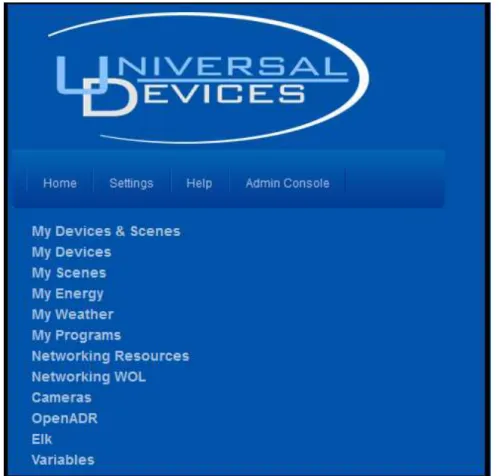
Figure 6: ISY’s Home Tab
You won’t be able to do much until you start configuring your ISY, but here is a summary of what you can do with the HTML Interface:
Home Tab:
My Devices & Scenes – This is where you will find a list of all INSTEON devices and scenes you have on your ISY. You can control your devices and scenes as well as check their current state. Use this page to turn lights and other devices on or off, adjust your thermostats, and much more.
My Devices – Same as My Devices and Scenes, but this shows only your devices.
My Scenes – Same as My Devices & Scenes, but this shows only your scenes. You will
learn more about Scenes in the section entitled 3 The Administrative Console.
My Weather (only available if the optional Climate Module has been installed on your ISY) – This item is where you can see weather information available to your ISY. More
My Programs – By clicking this item you can view the status of any Programs you have stored on your ISY and also control them. You will learn more about Programs in the
section entitled 3.3 The Programs/Details Tab.
Networking Resources (only available if the optional Network Resources Module has been installed on your ISY) – This section is where you can view and control any network resources you may have configured on your ISY. More information is available in the
section entitled 3.9.1 Network Module.
Networking WOL (only available if the optional Network Resources Module has been installed on your ISY) – This section is where you can view and control any Wake-On-LAN entries you may have configured on your ISY. More information is available in the section
entitled 3.9.1 Network Module.
Cameras– This section is where you can add and view network bases IP cameras.
Elk (only available if the optional ELK Security Module has been installed on your ISY) – This section is where you can view and control any resources available from your
ELK security system. More information is available in the section entitled 3.9.5 ELK
Security Module.
Variables – This section is where you can view and control any Variables you have configured on your ISY. More information is available in the section entitled 3.5 Variables.
Settings tab:
SubDevices – This option allows you to show or hide SubDevices. SubDevices are typically secondary buttons, such as non-load controlling buttons on KeypadLincs, etc.
Controllers – This option allows you to show or hide Controller-only devices, such as RemoteLincs and ControlLincs.
Disabled – This option allows you to show or hide disabled devices. Devices can be
disabled through the Admin Console, refer to 3.2.6 Other Functions (Restore, Disable,
Query, etc.) for further details.
Max Width – This option sets the width of the HTML interface.
Local Caching – Enabling this option tells the HTML interface to cache the node list to your system, potentially improving performance. If this option is enabled, however, you will
need to periodically hit Clear Cache (see below) to refresh the interface and see changes to
Clear Cache – This button clears the disk and memory cache of the HTML interface allowing you to see the latest changes to your node list.
Install Admin Console – This button installs a local copy of the Admin Console applet to your system, creating a desktop icon so you can launch the Admin Console quickly and easily.
Admin Console tab:
Launches the ISY’s Administrative Console (requires Java). The Administrative Console is where you will configure your ISY - adding devices, creating Programs, configuring the
optional IR interface, and MUCH more.
There may be other items available in the HTML interface depending on how your ISY is configured, and what optional modules you have purchased.
2.4
Launching the Administrative Console
The Administrative Console is where you will spend most of your time configuring and tuning the ISY, programming your devices, etc.
The best way to launch the Admin Console is from the following URL (requires internet access): http://isy.universal...com/994i/4.2.30
You can also install a copy of the Admin Console’s applet on your local PC (icon created on
desktop) by launching the following URL: http://isy.universal-devices.com/994i/admin.jnlp
Finally, you can also launch the Admin Console by clicking the link located on the ISY’s HTML Interface.
Once launched, you will again be asked to authenticate to your ISY. The default login information is:
Username: admin
Password: admin
In the future you may go directly to the ISY’s Administrative Console by appending /admin
to the URL. For example: http://192.168.0.101/admin
3
The Administrative Console
The Administrative Console is divided into several tabs, each used to configure different aspects of your ISY. This section provides information to help you take advantage of the
the user interface too detailed to include in this section – please refer to Appendix F: User Enhancement Details for a description of these enhancements.
The ISY’s Administrative Console automatically checks for the latest firmware release. When a new release is detected, the ISY provides a notification message and instructions on how to perform the update. In some cases, however, you may want to manually download and install a different firmware release. For example, some beta releases may contain important features or device support that you may want to utilize. The Administrative
Console will not notify you of beta firmware releases. Please refer to Appendix G:
Manually Upgrading Your Firmware for instructions on how to manually install a release.
3.1
Basic Configuration
Before getting started, it’s important to configure a few basic items on the ISY.
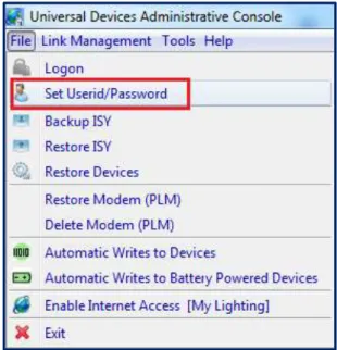
3.1.1 Setting the User ID and Password
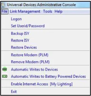
For security reasons, please change the default User ID and Password used to connect to
your ISY. Choose the Set Userid/Password option with the Administrative Console’s File
pull-down menu as shown below.
Figure 7: File Menu/ Set User ID/Password
Both the User ID and Password must be entered
Both the User ID and Password are case sensitive
Both the User ID and Password must be between 3 and 10 characters
The following characters are NOT allowed: < > / ; &
3.1.2
Setting the Time and Location
Click the ISY’s Configuration tab, then the System sub-tab, to set your time (used for
Program schedules) and location (used to calculate sunrise/sunset times).
Figure 8: Setting the Clock
Please be sure to check the Daylight Saving option if applicable in your area.
Also feel free to check and configure the NTP Server option if your ISY is able to access the internet. The ISY periodically syncs its clock with the specified NTP server to ensure accurate time. We recommend syncing every 24 hours, as too frequent connection attempts can result in the NTP server refusing the ISY’s request.
After adjusting your settings, please be sure to hit the Save button.
3.1.3
Keyboard Navigation
Please note that pull-down menus are accessible via keyboard shortcuts as follows:
Alt-F to access the File menu
Alt-L to access the Link Management menu
Alt-T to access the Tools menu
Alt-H to access the Help menu
Once a pull-down menu is opened, use your Arrow keys to navigate and the Enter key to
select a menu item. You can also enter letter keys to access many menu items quickly – look for menu items that contain underlined letters. For example, within the File pull-down menu, enter “b” to open the Backup ISY dialog box.
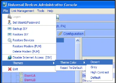
3.1.4 Themes
choose your scheme. Please note that the Administrative Console must be closed and re-opened for your Theme change to take effect.
Figure 9: Change Theme Menu
Desert Grey
Figure 10: Theme Samples
3.2
The Main Tab
The Main tab is where you can add, configure, and manage your INSTEON devices.
Figure 11: The Main Tab
The left-hand pane displays a hierarchy of folders, devices, and scenes contained within your ISY. The right-hand pane displays detailed information on the item you have selected.
3.2.1
Adding INSTEON Devices
Adding INSTEON devices to the ISY can be done via several methods. Some devices require a specific method; other devices can be added to the ISY in multiple ways. For more
Adding devices to the ISY is done through the Link Management pull-down menu. Within that menu are several different options:
Figure 12: The Link Management Menu
Start Linking. The majority of INSTEON devices can be added using this method. Once
this option is selected, simply go to each INSTEON device to be controlled and hold the Set
button for 3-5 seconds. The ISY will then see each device, and add it to the device list.
When you hold the Set button on each device, the device is added to the left-hand pane.
Adding devices to the ISY can take anywhere from a few seconds to minutes per device, depending on how many existing links are contained within each device. Please be patient.
Once you are finished adding devices, hit the Finish button which completes the process.
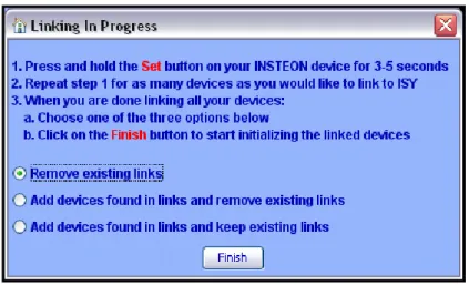
Before adding devices to the ISY, it’s important to understand the 3 different options presented:
Figure 13: Linking Options
Remove existing links. This option adds the device to the ISY, and also removes any existing links in the device. This is the default and the best option to choose if you would like a clean start, or if it is a brand new device.
Add devices found in links and remove existing links. This option not only adds the device, but also adds any devices that the device is linked to. Once complete, it removes any links contained within the devices. This helps save some time if you have a device you have already linked with other devices, but still clears out all links to give you a fresh start.
Adddevices found in links and keep existing links. This option not only adds the device, but also adds any devices that device is linked to. It also keeps any pre-existing links between devices, and builds ISY scenes out of those links. This is the best option to choose if you’d like to preserve all existing links between devices.
Link a ControLinc
Link a RemoteLinc
Add Button to IRLinc Receiver/Transmitter
Add Sensor to EZSnSRF
Add X10 Device to EZX10RF
The above 5 options are used to add the respective devices to the ISY. If you are adding one of these devices to the ISY, choose the corresponding menu option and follow the on-screen instructions.
New INSTEON Device. This method works much like the Start Linking method, with
one exception – instead of pressing the SET button on each device you must type in the
device’s INSTEON address. The ISY then initiates communications with the device to add it to your system. In most cases you can leave the Device Type option set to Auto Discover, but some devices may require you to specify the Device Type. For more
information please see: Appendix H: INSTEON Device Notes.
NOTE: This option is entitled New INSTEON/X10/A10 Device if the optional X10
Module is installed. Please see 3.9.6 X10 Module for more information.
Figure 14: New INSTEON/A10/X10 Screen
3.2.2 Adjusting Settings on INSTEON Devices
Some INSTEON devices have settings that can be changed through the ISY. For example, dimmable devices have On Levels (brightness levels when turned on) and Ramp Rates (speed at which a device is turned on) that can be adjusted.
To adjust settings on a device, simply click to select a device. Available settings will be displayed in the right-hand pane.
Some devices may have other options available. To find out more information for a
particular device, please see Appendix H: INSTEON Device Notes.
Making changes to INSTEON devices, whether adjusting settings or creating/modifying
Scenes (see 3.2.3 Creating INSTEON Scenes), can be a time consuming process. While
making minor changes can be relatively quick, making changes to large scenes (for example) can take many minutes.
PRO Series ONLY:
By default, the ISY is set to automatically write updates to devices as you make changes in the Admin Console. In some cases, you might prefer to queue your changes and write all changes to devices at a more convenient time. Therefore the PRO Series provides the option to either write automatically or manually.
To toggle this option, click the File menu:
Figure 15: File/Automatic Writes Options
Automatic Writes to Devices: When this option is on, changes are written automatically to devices. Toggle this option off to disable automatic writes. When toggled back on, all pending changes will be sent to devices.
Automatic Writes to Battery Powered Devices. This option toggles automatic writes only for battery powered devices. Most battery powered devices need to be manually set to linking mode to accept changes, so utilizing this option to queue up multiple changes can help save time.
Devices that have pending changes waiting to be written are marked with a green icon in the device tree as pictured here:
Figure 16: Devices with Pending Changes
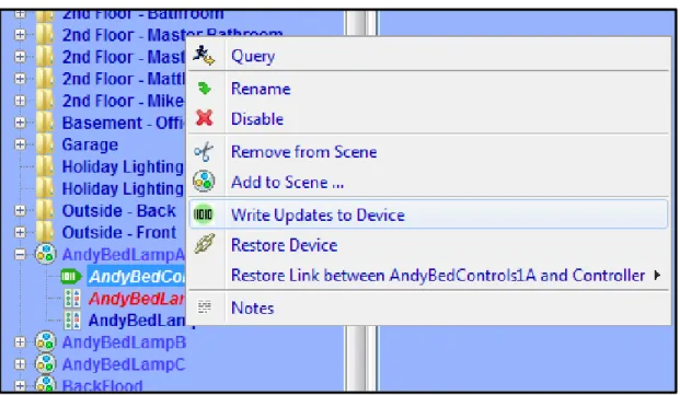
To write all pending changes for a single device (without turning Automatic Writes back
on), simply right-click the device and choose Write Updates to Device:
3.2.3 Creating INSTEON Scenes
Scenes are collections of INSTEON devices that react to and with one another in various ways. Scenes are comprised of both Responders and Controllers.
Responders are devices contained within scenes that only respond to commands issued to the scene. For example, a lamp module with a table lamp attached would likely be a
Responder to the scene. When the scene is turned on, the lamp module would turn on. When the scene is turned off, the map module would turn off. Responders are colored blue within a scene.
Controllers not only respond to commands issued to the scene, they also control the scene. An example of a Controller might be a button located on a Keypad – when that Keypad button is pressed, all members of the scene will respond as configured. Controllers are colored red within a scene.
To create a Scene, simply click the New Scene option under the Link Management
pull-down menu, or click the New Scene button on the ISY’s toolbar.
Figure 18: New Scene Screen
To add devices to a scene, simply right-click a device, choose Add to Scene…, and choose
the appropriate Scene. You can also hold the CTRL key down, click multiple devices, then
right-click and choose Add to Scene… to add multiple devices at once.
Figure 19: Choose Scene Screen
If appropriate, the ISY asks you if the device should be added to the Scene as a Responder or a Controller. Some devices (typically devices without buttons) cannot be Controllers.
To remove devices from a Scene, simply right-click a device in a Scene and choose Remove
from Scene. To remove an entire Scene, simply right-click the scene and choose Remove Scene.
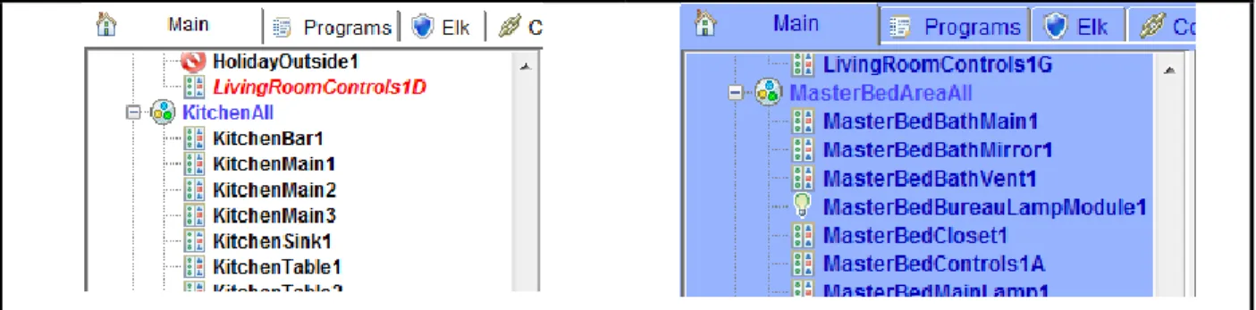
One example of a scene might be a group of 2 devices that control the same light – typically called a “virtual 3-way circuit.” For example, you might have 2 switches in your kitchen that you’d like to control your kitchen table light. One switch is physically attached to the kitchen table light, but you’d like the other switch to control it as well. In this case you would add both devices as Controllers. In the scene below, both devices in the scene are Controllers (shown below in red). This is commonly called “cross-linking.”
Figure 20: Cross-Linking
Another example of a scene might be a keypad button that you want to control multiple lights in a room. When the keypad button is turned on, you might want multiple devices to turn on at various levels to create a lighting “mood.” When the keypad button is turned off,
the devices would all turn off. In the screenshot below, the KitchenDinner scene contains multiple Responder devices (in blue) with a single Controller (in red):
Figure 21: Multiple Responders with 1 Controller
Scenes can contain multiple Controllers, and each Controller can be programmed to set Responders to various On Levels and Ramp Rates.
On Levels are levels at which a Responder is turned on when activated (25%, 75%, etc.). Devices can have multiple On Levels (one per Controller). Relay devices can only be On or Off.
Ramp Rates (dimmable devices only) are the speeds at which a device is turned on when activated. Use a slower ramp rate to cause a light to start dim and get brighter slowly. To set the properties of a scene, click on a Controller within a scene. The right-hand pane contains the options to set each scene member’s On Levels and Ramp Rates used when the highlighted Controller is pressed. Simply move the appropriate slider left or right to adjust the values. Once the slider is released, changes are saved to the device.
To set values when the ISY itself is the Controller (for example when controlled through the Administrative Console or through ISY Programs), click the scene itself on the left-hand pane.
In the example below, when the highlighted Controller is pressed the TheaterControls1A-Table device turns on to 60% and the TheaterMain1 and TheaterMain2 devices turn off. All devices are set to use a 2 second Ramp Rate.
Figure 22: Controller Properties
There are a couple of other options available when adjusting scenes:
Apply Changes To All Devices. This option merges all Responder sliders to one slider to make bulk changes easier. For example, if you want all responders in a scene to turn on to
50%, simply check the Apply Changes To All Devices option and drag the single slider to
50%.
Copy Scene Attributes From... As noted above, the ISY itself is also a Controller of every scene. If a Controller within a scene should use the same values the ISY uses when
controlling a scene, simply click this button to copy the values from the ISY over to the currently selected Controller.
NOTE: Once programmed, scenes operate independently of the ISY – all programming is saved to the INSTEON devices. If the ISY is turned off or is offline for some reason, programmed Scenes still operate as expected.
NOTE: It’s important that all links between devices are created from within the ISY. Avoid creating links manually between devices or using other software packages – unexpected results will occur.
3.2.4
Organizing INSTEON Devices and Scenes
Once added to your ISY, you can manage and organize your INSTEON Devices and Scenes in a variety of ways:
Rename. When added to the ISY, devices are named their INSTEON address by default. If
you right-click a device or scene, a Rename option is available to help make your devices
more identifiable. You can also rename by left-clicking to highlight, then hitting the F2 key. A dialog box pops up giving you several rename options if you’d like to rename associated devices as well.
Folders. Feel free to create folders to help organize your Devices and Scenes. Folders can be created by either right-clicking on the Network node (located on the left-hand pane) and choosing New Folder, or using the New Folder icon located on the Administrative Console’s top toolbar. Devices and Scenes can be dragged and dropped onto folders, or simply right-click a Device or Scene and choose Move To Folder and select the appropriate folder to move it to. Folders can also be moved within other Folders to create a nested hierarchy.
Delete. By deleting a Device or Scene you remove it completely from the ISY. The ISY also removes any links associated with any other Device or Scene.
NOTE: In order to delete a Device or Scene entirely from the node list, it must be located in the parent “My Lighting” folder. So, to delete a node, be sure to move it out to “My Lighting” first.
My Lighting. Clicking the My Lighting node on the left-hand pane displays a summary of all your devices, their current states, their INSTEON addresses, their device types and their firmware versions. You can sort by any field simply by clicking the appropriate column header (Name, Current State, Address, or Type).
3.2.5 Controlling INSTEON Devices and Scenes
The Admin Console also allows you to control your INSTEON devices and scenes. Simply click on a device or scene, and appropriate controls display on the bottom of the Console as follows:
Figure 23: Scene Controls
On. Clicking this button turns the INSTEON device or scene on to its programmed On Level
using its programmed Ramp Rate.
Off. Clicking this button turns the INSTEON device or scene off using it’s programmed
Ramp Rate.
Fast On. Clicking this button turns the INSTEON device or scene on to its maximum (100%) level instantly (ignoring its programmed On Level and Ramp Rate).
Fast Off. Clicking this button turns the INSTEON device or scene off instantly (ignoring its programmed Ramp Rate).
Brighten. Pressing and holding this button starts ramping up the brightness level of a dimmable INSTEON device. Release the button to stop the ramp up.
Dim. Pressing and holding this button starts ramping down the brightness level of a
dimmable INSTEON device. Release the button to stop the ramp down.
LED Brightness. Some INSTEON devices allow you to adjust the brightness of their LEDs by changing this value.
Some devices may have other controls or options available. To find out more information
for a particular device, please see Appendix H: INSTEON Device Notes.
3.2.6 Other Functions (Restore, Disable, Query, etc.)
There are several other functions available when working with INSTEON devices in the
Administrative Console’s Main tab. These functions are available by right-clicking the
device or Scene.
Restore Device. If an INSTEON device has lost all or some of its configuration, you can try using this function. This will attempt to re-write all links in a device, recreating all scenes to match the ISY’s internal database. Because a device restore can be a very lengthy process the ISY provides a confirmation window to avoid accidental restores as shown below:
Figure 24: Restore Confirmation Window
Disable. If an INSTEON device will be taken offline for an extended period of time, it might be desirable to use this function to stop the ISY from trying to access it.
Query. This function causes the ISY to communicate with the highlighted Device or Devices to determine their current states.
Group Devices. Some INSTEON devices create multiple entries within the ISY. For example, KeypadLincs have 6 or 8 nodes in the ISY (one for each button). You can choose to group these nodes together by right-clicking the primary node and using this function.
Write Updates to Device. If you have turned off “Automatic Writes to Devices” or
“Automatic Writes to Battery Powered Devices” you can manually update a Device with any pending changes using this function.
3.3
The Programs/Details Tab
The Programs/Details tab is where you can create ISY Programs. ISY Programs are the true power of the ISY, where you can extend the capabilities of INSTEON and other devices using timers, triggers, macros, etc. Programs also allow you to utilize the ISY’s optional IR receiver, optional modules, and more.
To open this tab, first click the Programs tab, then click the Details sub-tab. The
Programs/Details screen is divided into several sections. The left-pane is used to show your program hierarchy. As you create ISY programs and folders, they display here. The
bottom-left “Manage Programs” section holds several buttons used to create and manage
your Programs.
The top-right portion of the screen shows the details of a highlighted folder or program. The bottom right is where you create and edit your Program.
3.3.1 The Basics of ISY Programs
ISY Programs are created using simple buttons and pull-down menus. The ISY allows you to easily create simple programs, yet is flexible and sophisticated enough to allow powerful and complex programming.
NOTE: Unlike Scenes, Programs require that the ISY is online in order to function.
There are several buttons available on the bottom-left of the Administrative Console used to create and manage your Programs:
New Program. This button creates a new ISY Program. Once a Program is created, it can be edited and modified as needed.
New Folder. This button creates a new folder in your Program hierarchy.
Save Changes. The ISY requires that you save your changes before they become active. Please be sure to save periodically as you create and edit your ISY Programs.
Undo Changes. If you have made changes to your ISY Programs that you would like to discard, click this button that causes the ISY to revert to the last time your changes were saved.
3.3.2 Creating Your First Program
To create a Program click the New Program button and a new program appears.
Figure 25: Creating a Program
The ISY prompts you to name your program – type in something descriptive so you can easily identify it in the future.
Figure 26: Naming a Program
Once you name your program click the If statement to set your conditions.
Figure 27: If Statement
Once highlighted, the bottom portion of the screen allows you to set your conditions using simple buttons and pull-down menus. For this example, we will create a program to turn your front door lights on at sunset.
To set your sunset condition, click the Schedule button and change the right-most drop
Figure 28: Schedule at Sunset
Once your Sunset condition is set, click Add to ‘If’ and you will see the If statement added
to the top portion of the screen, which shows the actual program you are creating.
Figure 29: Adding to the If Statement
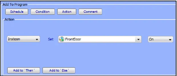
Next, click on the Then statement to highlight it. The Then portion of a program runs once
the If portion of a program is true. At the bottom of the screen choose the device or scene that you want to turn on at sunset.
Figure 30: Adding a Then Statement
This time hit the Add to ‘Then’ button to add the Then statement to your program.
Figure 31: Entering a Then Statement
Hit the Save Changes button to save your program, and you’re done! In just a few steps
we’ve created a simple program to turn on your front door lights at sunset.
But, let’s say we wanted something slightly more sophisticated. Say we want to turn the lights on 30 minutes AFTER sunset, and turn them off at 10pm. To do that, we’ll make a couple of quick adjustments to the program.
Figure 32: Changing the If Statement
Once the statement is highlighted we can edit it on the bottom of the screen. Change the
Time Is pull-down menu to a From and change the middle numeric value to 30. Then
change the For pull-down menu to To and change the values to 10pm as shown below:
Figure 33: Updating the Schedule
Click the Update button to change the highlighted statement. Clicking the Add to ‘If’
button would add an additional IF statement, which is not what we want to do in this case. The ELSE portion of a program runs once the IF statement is no longer true. After 10pm the IF statement is no longer true, so the ELSE statement runs. Next click the ELSE statement on the top portion of the screen to highlight it, and on the bottom portion set your Front Door lights to turn off.
Figure 34: Adding an Else Statement
Click Add to ‘Else’ and your final program should look like this:
Figure 35: Enhanced Sample Program
Hit the Save Changes button in the bottom left, and your enhanced program is complete!
NOTE: Always remember to hit the Save Changes button when finished creating or editing your programs! Changes are not saved to the ISY until this button is pressed.
There is virtually an unlimited number of functions you can perform using ISY programs.
For more examples, see Appendix I: Sample ISY Programs.
3.3.3 Building Your Programs
There are a variety of on-screen buttons to help build your Programs to suit your needs. Programs are not limited to one condition or action – you can add multiple IF, THEN, and ELSE statements to your program. When adding multiple lines, be sure to choose AND or OR as appropriate.
When working with Programs containing multiple lines, additional buttons appear to help arrange your lines and group them together with parentheses.
Figure 36: Additional Program Buttons
To remove a line, simply highlight it and click Remove Line. To rearrange your lines,
highlight them and click Move Line Up or Move Line Down.
To group conditions together, use the Add And (..) and Add Or (..) buttons as shown
below:
Figure 37: Grouping Conditions
This program executes only if the time is 9:45pm and the BasementControls1A device is On or if the time is 10:00pm and the BasementControls1A device is Off.
Click the Comment button to add comments to your program as needed. Click the Update
Figure 38: Adding Program Comments
To temporarily disable a program, un-check the Enabled box on the right-hand side of the
screen and hit the Save Changes button. Alternatively, simply right-click a program and
choose Disable.
Figure 39: Temporarily Disable a Program
Disabled programs are displayed with a red X in the Program list as shown below:
Figure 40: Disabled Programs
Programs that have changes and need to be saved are displayed in the program list with a green arrow:
Figure 41: Unsaved Programs with Changes
3.3.4 Program Schedules
In the Add To Program button section, click Schedule to add a Schedule to your Program.
Schedules allow you to add IF statements based on time of day, ranges of times, sunrise/sunset, days of the week, etc.
For example, a program that would run from 6am to 12pm:
Or a program that would run at 10pm on weekdays:
Figure 43: Schedule Screen – Time & Day
Once your Schedule statement is complete, click the Add to ‘If’ button to add it to your
program.
3.3.5
Program Conditions
In the Add To Program button section, click Condition to add a Condition to your
Program.
Conditions add other criteria to your IF statement. When adding a Condition to your Program, be sure to choose if you would like it to be added as an AND or OR.
Types of Conditions are:
Statusconditions are true if a selected INSTEON device is at the state you specify. You can check to see if a device is On, Off, is Not On, is Not Off; if a dimmable device is at a specific level, if it’s greater than a specific level, etc.
On means a device is at 100% brightness. So, if your program is checking to see if a
For example, to see if your kitchen light is at 100% brightness you could do the following:
Figure 44: Status Condition – 100% Bright
But, to see if the same light is on at ANY brightness you might do this instead:
Figure 45: Status Condition – Any Brightness
Control conditions trigger only if a specified switch is pressed. The following types of conditions are available (not all options are available for all devices):
On Off
Fast On (double-tap ON)
Fast Off (double-tap OFF)
Fade Up (press and hold ON)
Fade Down (press and hold OFF)
Fade Stop (release of a press and hold)
Bright (bright button pressed)
Dim (dim button pressed)
For example if you want to trigger a program if your Kitchen switch is double-tapped ON (Fast On) you could do the following:
Figure 46: Fast On Condition
Program Conditions check to see whether or not other ISY Programs are currently True or False.
X10 Conditions trigger programs when X10 commands are received by the ISY. For example, to run a program if an X10 M1 ON command is received:
Figure 47: X10 Condition
Variable Conditions trigger programs based on the value of a defined variable. You can
read more about Variables in 3.5 Variables.
IR Conditions trigger programs when IR commands are received from a remote control. See 3.5 Variables for more information.
Module Conditions trigger programs based on optional ISY modules, such as the Electricity
meter module or the Climate module. See 3.9 Optional Modules for more information.
ELK conditions trigger programs based on the state of available ELK resources, assuming you have an ELK security system installed and communicating with your ISY, and have the
optional ELK Security System module installed. See 3.9.5 ELK Security Module for more
information.
3.3.6 Program Actions
In the Add To Program button section, click Action to add an Action to your Program.
Program Actions are commands that are run when the IF statement is true (a THEN action) or if the IF statement is no longer true (an ELSE action). When adding an Action to your
program, be sure to click the Add to ‘Then’ or Add to ‘Else’ button depending on your
Insteon (Insteon/X10 with the optional X10 option): Sends INSTEON commands to devices or scenes to turn them ON, OFF, etc. Not all options are available for all devices: ON (send a standard ON command)
OFF (send a standard OFF command)
FAST ON (turn device full on ignoring programmed on level or ramp rate) FAST OFF (turn device full off ignoring programmed ramp rate)
FADE UP (start the ramp up of a dimmable device
FADE DOWN (start the ramp down of a dimmable device) FADE TOP (stop the ramping up or down of a dimmable device) BRIGHT (small increase in brightness of a dimmable device) DIM (small decrease in brightness of a dimmable device) QUERY (query the current state of a device)
BEEP DURATION (causes a supported device or scene to emit a beep) BACKLIGHT LEVEL (sets the backlight level on a supported device)
Send X10: Sends X10 commands to X10-compatible devices. Using this feature, ISY programs can control a wide range of X10-compatible devices.
Notify: Sends an email or SMS text message to recipients. Please see 3.7 Notifications for more information.
Program: Runs or modifies other ISY programs. The following options are available: Run (If) (runs the IF portion of a program)
Run Then (runs the THEN portion of a program) Run Else (runs the ELSE portion of a program) Stop (stops a currently running program) Enable (enables a disabled program)
Disable (disables and enabled program)
Enable Run at Startup (sets a program to run at startup) Disable Run at Startup (sets a program to NOT run at startup)
Wait: Creates a pause in a running program. For example, to turn your driveway lights off 5 minutes after your front door lights are turned off, you could do the following:
Figure 48: Wait Action
If the Random checkbox is checked, a random time between 0 and the specified time is
used. For example, this program would wait between 0 and 5 minutes:
Figure 49: Random Action
Repeat: Repeats an action or group of actions multiple times. If the Random button is checked, a random number of repeats between 0 and the specified value is used.
For example, to flash your driveway lights on and off 5 times, every 2 seconds, you could:
Figure 50: Flash Lights ON and OFF
Variable: Allows you to adjust the value of a defined variable within program. Please see
3.5 Variables for more information.
Adjust Scene: Adjusts the On Levels and Ramp Rates of devices or scenes. For example, use this function to adjust scenes so that they turn on at brighter levels during the day and perhaps at dimmer levels during the evening. Please keep in mind that many devices require a reboot before On Level or Ramp Rate changes take effect, so this function may not be useful in all cases.
System: Notifies compatible clients of energy related alerts.
Other Actions may be available depending on what optional modules you may have
installed. For more information, see 3.9 Optional Modules.
3.3.7 Program Folders
To create a new folder, simply click the New Folder button on the bottom-left corner of the
screen. You can also create new folders by right-clicking on the program hierarchy
(left-hand side of the screen) and choosing New Folder.
Folders can be used to store Programs to help organize them by type, category, etc. Folders can also have conditions set on them to aid in program functionality. For example, you could create a Vacation Programs folder that contains only programs that should run when you are on vacation. In the following example, the user turns a keypad button called “GarageControls2E” on if they are going away on vacation. The folder is set with the following conditions so that the contained programs run only if that vacation keypad button is on:
Figure 51: Folder Conditions
To set conditions on a folder, simply click the folder to select it and adjust conditions as you would any ISY Program.
3.3.8
Other Functions
Status. To quickly view the current status of a Program, simply right-click it and choose Status which brings you to the Program Summary tab with the selected program
highlighted.
Copy / Copy Tree. To duplicate a program, simply right-click the Program and choose Copy. This is especially useful if creating several similar Programs. To duplicate a Folder and all contained Programs, right-click the Folder and choose Copy Tree.
Import / Export. Programs can be imported and exported to the ISY by right-clicking a Program or Folder and choosing the desired function.
Find / Replace. Right-click within your Program hierarchy to start a Fine / Replace. This function allows you to search your programs for specific devices or text strings, and optionally replace the results.
Copy To Clipboard. To copy a specific Program as text to your clipboard, simply right-click it and choose Copy To Clipboard. The text can then be pasted into practically any Windows application, text editor, web browser, etc.
Rename. To rename a Program or Folder, simply right-click it and choose the Rename function.
Remove. To remove a Program or Folder (and all contained Programs), simply right-click it and choose Remove. Remember to hit the SAVE CHANGES button when complete.
3.4
The Programs/Summary Tab
The Programs/Summary page displays a list of all your Programs and Folders, and
information about each. To open this tab, first click the Programs tab, then the Summary
sub-tab. Here are the columns of information available:
Name: the Program or Folder’s name.
Enabled: shows whether the Program is currently enabled or disabled.
Run At Startup: shows whether the Program is set to run at startup.
Activity: shows if the Program is currently running or is idle.
Status: shows if the Program’s IF statements are currently true or false.
Path: the Folder that the program is located in.
Last Run Time: the last time the Program’s IF statements were evaluated.
Last Finish Time: the last time the Program completed.
Next Scheduled Run: the next time the Program is scheduled to run, if applicable. Each column can be sorted by clicking its column heading.
There is a toolbar on the top portion of the screen that you can use to interact with ISY programs in a variety of ways.
Figure 52: ISY Toolbar
To perform an action on a program, simply selecting it by clicking on it, click the left-most pull-down menu labeled “Choose” to select an action, and click the Apply button.
Available actions are:
Enable – enable a program that has been disabled
Disable – disable a program so that it will not run
Run (If) – force the evaluation of the IF statement and run the program
Run Then – force the run of the THEN portion of a program
Enable Run At Startup – set a program so that it automatically starts running when the ISY reboots
Disable Run At Startup – set a program so that it will not automatically run when the ISY reboots
On the right-most side of the tool bar is the Edit button which brings you to the Program
Details tab and allows you to edit the currently highlighted program. The Refresh button
forces a refresh of the screen.
3.5
Variables
Variables can be incredibly useful when creating programs on the ISY. Variables can be stored, modified using arithmetic operations, and compared. You can use variables to provide information, trigger programs, etc.
To view your variables, click on the Programs tab then the Variables sub-tab.
There are two different types of variables (Integer and State), each divided into a separate sub-tab. The only difference between the two is that State variables create ISY events when modified, so they can be used to trigger ISY Programs.
For example, if you’d like to create an ISY Program that runs only when a variable is or reaches a certain value, use a State variable. Otherwise, if the variable’s value will not be used to trigger a program, feel free to use the simpler Integer variable.
3.5.1 Creating Variables
To create a new variable, click the Add button on the bottom of the screen. Here is a list of each column and a quick definition:
Name – This is the user-defined name of the variable. Choose a name that’s descriptive so that you’ll be able to quickly identify the variable you want to use in ISY Programs.
Init – This is the initial value of the variable, the value it has if the ISY is rebooted. This can be defined here and also updated using ISY Programs so that a variable value can persist even if the ISY loses power.
Value – This is the current value of the variable. Again, this can be defined here and also modified via arithmetic operations using ISY Programs.
3.5.2 Using the Status of Variables in Programs
You can use the If portion of an ISY Program to check the state of a variable. To do those, choose Variable when defining your If statement, then choose your Variable, then choose what you’d like to check for.
For example, you can check to see if a Variable is a certain value, if it’s NOT a certain value, if it’s greater than a certain value, etc. You can also compare one variable to another. In this screenshot we are checking to see if a Variable called Counter is greater than 3:
Figure 53: Counter Variable
3.5.3
Modifying Variables in Programs
You can also use ISY Programs to modify variables. You can perform standard arithmetic functions on a variable, change a variable to a specific value, or modify a variable’s Init state.
The following functions can be performed on a variable:
Command Function Performed
= Sets the variable to a specified value. += Adds to the variable
-= Subtracts from the variable *= Multiples the variable /= Divides the variable
%= Performs a remainder function on the variable &= Performs an AND (binary) function on the
variable
|= Performs an OR (binary) function on the variable
=Random Sets the variable to a number between 1 and the specified number
Init To Sets the variable’s initial value
Figure 54: Increment a Variable by 1
This example sets the Init value of a variable to the current value of another variable:
Figure 55: Set a Variable’s Initial Value
3.5.4 Using Variables in Notifications
Variables can also be useful when sending notifications. Say you have a variable that you use to count the number of times a motion sensor is trigged overnight. You could send yourself an email in the morning telling you how many times it was triggered.
Your notification might look like this:
3.6
The Integrated IR Receiver
If your ISY came equipped with an integrated IR receiver (model numbers that contain “/IR”), Programs can be triggered using an RC5-compatible remote control. To program IR codes into the ISY, click the Configuration tab, then the IR sub-tab.
The IR configuration page lists all IR codes currently recognized by the ISY. The first
column titled “Name” allows you to customize the name of a stored IR code. Simply double-click the IR code you’d like to change, and type the desired name. This is how the IR code will be listed under ISY Program Conditions.
The “IR Code” is an internal number used to identify the IR code. It cannot be change and for the most part should be ignored.
The “Status” column contains the last Condition received from a particular IR code. The following conditions are available:
Pressed – indicates the remote control button was pressed and released normally.
Double-Pressed – indicates the remote control button was pressed twice quickly (similar to a mouse double-click).
Held – indicates the remote control button was pressed and held (not yet released).
Released – indicates the remote control button was pressed and held, then released. The above Conditions are available in ISY Programs, allowing you to control your home in a wide variety of ways from a simple remote control.
There are also 3 buttons on the bottom of the IR Configuration Page:
Save – this button saves the currently displayed IR codes to the ISY.
Reload – this button aborts any IR codes learned since the last Save, and “reloads” the last saved IR database from the ISY.
Restore Defaults – this button restores the ISY to its default, blank IR database.
3.6.1 Using the 40 Default IR Codes
The ISY is able to download 40 pre-configured IR codes. These 40 pre-configured codes make it easier to configure remote controls that contain the ISY in their database (such as the Logitech Harmony), or remote controls that can import CCF files.