Symantec Backup Exec™
3600 R2 Appliance
Getting Started Guide
The software described in this book is furnished under a license agreement and may be used only in accordance with the terms of the agreement.
PN: 21239090
Legal Notice
Copyright © 2012 Symantec Corporation. All rights reserved.
Symantec and the Symantec Logo and Backup Exec are trademarks or registered trademarks of Symantec Corporation or its affiliates in the U.S. and other countries. Other names may be trademarks of their respective owners.
This Symantec product may contain third party software for which Symantec is required to provide attribution to the third party (“Third Party Programs”). Some of the Third Party Programs are available under open source or free software licenses. The License Agreement accompanying the Software does not alter any rights or obligations you may have under those open source or free software licenses. Please see the Third Party Legal Notice Appendix to this Documentation or TPIP ReadMe File accompanying this Symantec product for more information on the Third Party Programs.
The product described in this document is distributed under licenses restricting its use, copying, distribution, and decompilation/reverse engineering. No part of this document may be reproduced in any form by any means without prior written authorization of Symantec Corporation and its licensors, if any.
THE DOCUMENTATION IS PROVIDED "AS IS" AND ALL EXPRESS OR IMPLIED CONDITIONS, REPRESENTATIONS AND WARRANTIES, INCLUDING ANY IMPLIED WARRANTY OF MERCHANTABILITY, FITNESS FOR A PARTICULAR PURPOSE OR NON-INFRINGEMENT, ARE DISCLAIMED, EXCEPT TO THE EXTENT THAT SUCH DISCLAIMERS ARE HELD TO BE LEGALLY INVALID. SYMANTEC CORPORATION SHALL NOT BE LIABLE FOR INCIDENTAL OR CONSEQUENTIAL DAMAGES IN CONNECTION WITH THE FURNISHING,
PERFORMANCE, OR USE OF THIS DOCUMENTATION. THE INFORMATION CONTAINED IN THIS DOCUMENTATION IS SUBJECT TO CHANGE WITHOUT NOTICE.
The Licensed Software and Documentation are deemed to be commercial computer software as defined in FAR 12.212 and subject to restricted rights as defined in FAR Section 52.227-19 "Commercial Computer Software - Restricted Rights" and DFARS 227.7202, "Rights in Commercial Computer Software or Commercial Computer Software Documentation", as applicable, and any successor regulations. Any use, modification, reproduction release, performance, display or disclosure of the Licensed Software and Documentation by the U.S. Government shall be solely in accordance with the terms of this Agreement.
Symantec Corporation 350 Ellis Street
Mountain View, CA 94043 http://www.symantec.com
Printed in the United States of America. 10 9 8 7 6 5 4 3 2 1
Technical Support
Symantec Technical Support maintains support centers globally. Technical Support’s primary role is to respond to specific queries about product features and functionality. The Technical Support group also creates content for our online Knowledge Base. The Technical Support group works collaboratively with the other functional areas within Symantec to answer your questions in a timely fashion. For example, the Technical Support group works with Product Engineering and Symantec Security Response to provide alerting services and virus definition updates.
Symantec’s support offerings include the following:
■ A range of support options that give you the flexibility to select the right amount of service for any size organization
■ Telephone and/or Web-based support that provides rapid response and up-to-the-minute information
■ Upgrade assurance that delivers software upgrades
■ Global support purchased on a regional business hours or 24 hours a day, 7 days a week basis
■ Premium service offerings that include Account Management Services For information about Symantec’s support offerings, you can visit our Web site at the following URL:
www.symantec.com/business/support/
All support services will be delivered in accordance with your support agreement and the then-current enterprise technical support policy.
Contacting Technical Support
Customers with a current support agreement may access Technical Support information at the following URL:
www.symantec.com/business/support/
Before contacting Technical Support, make sure you have satisfied the system requirements that are listed in your product documentation. Also, you should be at the computer on which the problem occurred, in case it is necessary to replicate the problem.
When you contact Technical Support, please have the following information available:
■ Hardware information
■ Available memory, disk space, and NIC information ■ Operating system
■ Version and patch level ■ Network topology
■ Router, gateway, and IP address information ■ Problem description:
■ Error messages and log files
■ Troubleshooting that was performed before contacting Symantec ■ Recent software configuration changes and network changes
Licensing and registration
If your Symantec product requires registration or a license key, access our technical support Web page at the following URL:
www.symantec.com/business/support/
Customer service
Customer service information is available at the following URL: www.symantec.com/business/support/
Customer Service is available to assist with non-technical questions, such as the following types of issues:
■ Questions regarding product licensing or serialization
■ Product registration updates, such as address or name changes
■ General product information (features, language availability, local dealers) ■ Latest information about product updates and upgrades
■ Information about upgrade assurance and support contracts ■ Information about the Symantec Buying Programs
■ Advice about Symantec's technical support options ■ Nontechnical presales questions
Support agreement resources
If you want to contact Symantec regarding an existing support agreement, please contact the support agreement administration team for your region as follows:
[email protected] Asia-Pacific and Japan
[email protected] Europe, Middle-East, and Africa
[email protected] North America and Latin America
Technical Support
... 4Chapter 1
Introduction
... 9About the Backup Exec 3600 Appliance ... 9
About the documentation ... 9
Hardware dimensions ... 10
Power specifications ... 10
About disk modules and drives ... 11
About the rear panel components ... 11
Software overview ... 13
System requirements ... 13
Chapter 2
Configuration
... 15About changes to appliance configuration ... 15
Factory settings ... 16
Configuration guidelines ... 17
Configuring the appliance ... 17
About adding a Backup Exec 3600 Appliance to an existing Backup Exec environment ... 18
Mounting the appliance in the rack ... 19
Connecting cables and starting the appliance ... 21
Setting the IP address and verifying the factory test results ... 21
Performing the initial configuration ... 22
Network Setup options ... 23
DNS Configuration options ... 24
DNS suffix guidelines ... 25
Joining a domain ... 25
Confirming the initial configuration ... 26
Installing system updates or patches ... 27
Update information tab options ... 28
Connecting a tape device to the appliance ... 30
About post-configuration tasks and options ... 31
Configuring system preferences on the Settings tab ... 32
Viewing hardware component fault information ... 36
About server roles ... 37
Contents
About recreating selection lists after server role configuration
changes ... 38
About changing the host name ... 38
Chapter 3
Removing and replacing components
... 39About removing and replacing components ... 39
Removing a disk drive module ... 40
Replacing one disk drive module ... 41
About replacing more than one disk drive module ... 42
About replacing the appliance ... 42
About removing and replacing power supply modules ... 42
Removing a power supply module ... 43
Replacing a power supply module ... 43
About replacing hardware ... 44
About hot-swappable, customer-replaceable units (CRUs) ... 44
Chapter 4
Environmental specifications
... 45About environmental specifications ... 45 Contents
Introduction
This chapter includes the following topics: ■ About the Backup Exec 3600 Appliance ■ About the documentation
■ Hardware dimensions ■ Power specifications
■ About disk modules and drives ■ About the rear panel components ■ Software overview
About the Backup Exec 3600 Appliance
The Backup Exec 3600 Appliance provides data protection with comprehensive backup and recovery in a single, easy-to-use appliance.
This version provides access to additional Ethernet interfaces; NIC3/eth2 and NIC4/eth3.
See “About changes to appliance configuration” on page 15.
About the documentation
This document provides quick instructions to install and set up your appliance. Documentation changes may occur after the document's initial release. Documents on the Symantec Technical Support Web site contain the most up-to-date information.
See the following site for the latest information about the appliance.
1
http://www.symantec.com/business/support/index?page=landing&key=60491 http://www.symantec.com/docs/DOC5211
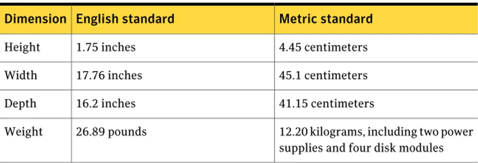
Hardware dimensions
The Backup Exec 3600 Appliance is 1U (one rack unit) high. 1U equals 1.75 inches (4.45 centimeters). The appliance can be installed in a rack cabinet that is 19 inches (1 inch = 2.54 centimeters) wide and 40 inches deep (minimum). Appliance specifications include the folllowing dimensions:
Table 1-1 Appliance dimensions
Metric standard English standard Dimension 4.45 centimeters 1.75 inches Height 45.1 centimeters 17.76 inches Width 41.15 centimeters 16.2 inches Depth
12.20 kilograms, including two power supplies and four disk modules 26.89 pounds
Weight
See “Power specifications” on page 10.
Power specifications
Power specifications include the following items:
Table 1-2 Power specifications
Max Input Current at Min Vrms Power Off VAC Start up VAC Max Rated Min Parameter 6 Arms < 80VAC < 85VAC 132 Vrms 100-127 Vrms 90 Vrms 120VAC 3 Arms 264 Vrms 200-240 Vrms 180 Vrms 220VAC 63 Hz 47 Hz Frequency
Maximum power consumption: 400W Introduction
Hardware dimensions
About disk modules and drives
The Backup Exec 3600 Appliance contains four externally accessible disk bays. Each bay holds one disk module, which includes a disk carrier and a hard disk drive (HDD).
These four hot-swappable SAS drives have a 3.5 inch form factor, have a capacity of 2 TB, and are labeled 0 through 3, from left to right.
To maintain air flow, the bays must never be empty. A blank carrier may be used if necessary.
You can hot-swap only one disk drive. If you have two drives that do not work properly, you must shut down the entire system before removing more than one drive.
You must perform a full system shutdown before disconnecting the Backup Exec 3600 Appliance from a power source, or turning off power. To turn off the device correctly, stop reading and writing data on the disks first. Then send a shutdown command through the operating system.
About the rear panel components
The rear panel of the Backup Exec 3600 Appliance contains two USB 2.0 ports, one serial port, one VGA port and four operational NIC Ethernet ports. NIC1, NIC2, NIC3, and NIC4 are the Ethernet ports. NIC1 has a preset IP address;
172.16.111.111. NICs 2, 3, and 4 are configurable. These NICs are not bonded or teamed. The NIC5 port is reserved for Symantec Technical Support personnel only. The PCIe slot has a SAS HBA card installed. You can attach a tape device to the SAS card.
See “Connecting a tape device to the appliance” on page 30.
System fans and AC power connections are located on the left-hand side of the rear panel. It is recommended to have both power modules attached and turned on to the main AC power source. If one module or source fails, the other module maintains power to the system without interruption.
11 Introduction
The following list identifies the components of the rear panel. ■ 1 - Power supply locks
■ 2 - Power sockets ■ 3 - Power LEDs
■ 4 - Top cover thumb screw
■ 5 - NIC5 (used as an RMM Access port)
■ 6 - PCIe expansion slot with SAS HBA card installed ■ 7 - Power cords
■ 8 - NIC ports 1 and 2 ■ 9 - VGA port
■ 10 - NIC ports 3 and 4 ■ 11 - USB ports ■ 12 - Serial port ■ 13 - Ethernet cables ■ 14 - I/O expansion modules
The following list provides assignments for the five NIC/Ethernet ports. ■ NIC1 - Private Ethernet port (connecting the appliance to a Windows PC or
laptop)
■ NIC2 - Public Ethernet port (connecting the appliance to the customer's production network)
■ NIC3 - Public Ethernet port (connecting the appliance to the customer's production network)
Introduction
About the rear panel components
■ NIC4 - Public Ethernet port (connecting the appliance to the customer's production network)
■ NIC5 - Reserved for technical support only. Not for use by customers. ■ Serial port, not operational at this time.
Software overview
The Backup Exec 3600 Appliance is preloaded with the Backup Exec embedded Total Protection suite license and the Essential Protection Suite license. A USB 2.0 drive is provided so that you can restore the original factory image, if needed. The Backup Exec 3600 Appliance Web UI provides appliance management. The Web UI monitors the appliance and provides hardware component information. PowerShell CLI options let you make post-configuration changes, if needed. PowerShell also lets you turn the appliance on and off. You must have Windows PowerShell 2.0 on the PC to which the appliance is attached. More information regarding PowerShell is found in the Symantec Backup Exec 3600 Administrator’s
Guide.
See “System requirements” on page 13.
System requirements
System requirements include the following items:
Table 1-3 System requirements
Description Item
The Backup Exec 3600 Appliance supports Internet Protocol version 4 (IPv4). Internet Protocol version 4
13 Introduction
Table 1-3 System requirements (continued)
Description Item
If you use IE9, you must add the appliance URL to the Trusted Sites zone to see all Web UI functionality.
You must use Internet Explorer in Document Compatibility mode or view.
Internet Explorer 7 or later
If you use Firefox, you must accept the “exception” and “confirm security exception” before you access the Appliance Web UI.
Mozilla Firefox 3.x or later Introduction
Software overview
Configuration
This chapter includes the following topics: ■ About changes to appliance configuration ■ Factory settings
■ Configuration guidelines ■ Configuring the appliance
■ About adding a Backup Exec 3600 Appliance to an existing Backup Exec environment
■ Mounting the appliance in the rack
■ Connecting cables and starting the appliance
■ Setting the IP address and verifying the factory test results ■ Performing the initial configuration
■ Confirming the initial configuration ■ Installing system updates or patches ■ Connecting a tape device to the appliance ■ About post-configuration tasks and options ■ About server roles
About changes to appliance configuration
This release of the Backup Exec 3600 Appliance includes the Backup Exec software and an appliance. The appliance and software are specifically designed to work together. Therefore, some changes have occurred since the software-only releases.
2
One significant change from software-only releases is the method of connecting to the appliance. Previous releases required that you connect a mouse and keyboard to the server onto which the software was loaded.
The software is pre-installed on the Backup Exec 3600 Appliance. The only correct initial connection to the appliance is with a Windows computer or laptop. Connect an Ethernet cable between the computer and the NIC1/eth0 port on the appliance. The Ethernet cable must be a cross-over cable or you must ensure that the laptop connection to the appliance is Gigabit Ethernet. Another option is to install a switch that ensures proper connectivity.
Review the configuration guidelines and process before you start.
Warning:Do not use a monitor, a mouse, and a keyboard to connect to the appliance. This type of connection prevents you from logging in. You may have to restore factory settings.
See “Software overview” on page 13. See “Configuration guidelines” on page 17. See “Configuring the appliance” on page 17.
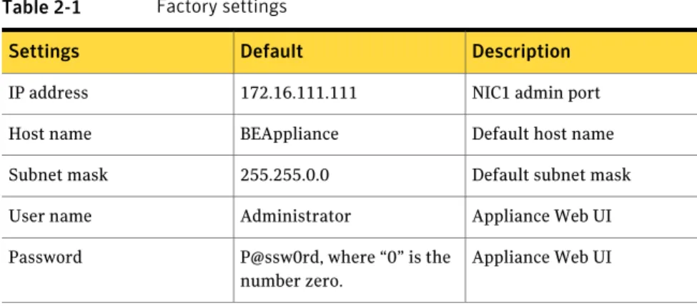
Factory settings
The Backup Exec 3600 Appliance is shipped with preconfigured settings and a plug-in.
Note:The preconfigured plug-in is a Nirvanix cloud plug-in. Configuration
Factory settings
Table 2-1 Factory settings
Description Default
Settings
NIC1 admin port 172.16.111.111
IP address
Default host name BEAppliance
Host name
Default subnet mask 255.255.0.0
Subnet mask
Appliance Web UI Administrator
User name
Appliance Web UI P@ssw0rd, where “0” is the
number zero. Password
Configuration guidelines
Use the following configuration guidelines to deploy new appliances. The instructions in this section help you set up your appliance and configure it so that you can start using the appliance quickly. Post-configuration tasks for your system can be performed at a later date.
Before you start the configuration, make sure that you have the following information:
■ Customer network IP address, subnet mask IP address, and gateway IP address ■ Appliance host names
■ Appliance passwords
■ Customer DNS server and suffix names
Note:If DNS is used, make sure that the appliance host name is DNS resolvable (FQDN and short name).
See “Configuring the appliance” on page 17. See “Factory settings” on page 16.
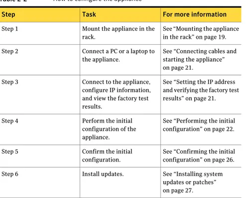
Configuring the appliance
Use the following steps to set up your appliance and configure it. Ensure that you have the necessary information to perform the configuration.
See “Configuration guidelines” on page 17.
17 Configuration
Table 2-2 How to configure the appliance
For more information Task
Step
See “Mounting the appliance in the rack” on page 19. Mount the appliance in the
rack. Step 1
See “Connecting cables and starting the appliance” on page 21.
Connect a PC or a laptop to the appliance.
Step 2
See “Setting the IP address and verifying the factory test results” on page 21. Connect to the appliance,
configure IP information, and view the factory test results.
Step 3
See “Performing the initial configuration” on page 22. Perform the initial
configuration of the appliance.
Step 4
See “Confirming the initial configuration” on page 26. Confirm the initial
configuration. Step 5
See “Installing system updates or patches” on page 27. Install updates.
Step 6
See “About adding a Backup Exec 3600 Appliance to an existing Backup Exec environment” on page 18.
About adding a Backup Exec 3600 Appliance to an
existing Backup Exec environment
You can add a Backup Exec 3600 Appliance to an existing Backup Exec environment. The appliance can back up only the agents that run Backup Exec 2012. The existing Backup Exec servers should run Backup Exec 2012 (fully patched), or later, before the addition of the appliance.
You can add a Backup Exec 3600 Appliance as a managed Backup Exec server in a CASO environment. You need to upgrade the other servers to Backup Exec 2012 before the addition of the appliance.
Several tape devices and autoloaders are compatible with the Backup Exec 3600 Appliance.
You can find a list of compatible types of storage at the following URL: http://entsupport.symantec.com/umi/V-269-2
Configuration
About adding a Backup Exec 3600 Appliance to an existing Backup Exec environment
Mounting the appliance in the rack
This section describes the rack mounting of the appliance. Be sure to use standard safety and work procedures.
Standard mounting rails are included in the shipping box to accommodate Standard Enterprise square hole 19” racks. If your racks require different rails, contact Symantec Technical Support.
Note:Symantec recommends mounting appliances in the lower portion of a rack to help lower the center of gravity.
See “Configuring the appliance” on page 17.
To mount the appliance in the rack
1
Install the slide rail to the rack.2
Place the top fastener into the rail hole.3
Snap the edge of the fastener down.4
Insert the bottom fastener and make sure that it is secure.5
Fully extend the rails forward.19 Configuration
6
Lower the chassis onto the extended rails.7
Be sure that the three locking pins on the sides of the chassis fit into the three slots in the extended rails.Note:The following drawings show an empty chassis. Your appliance is fully loaded, with the chassis cover installed, when it arrives from the factory. The following drawings show a generic chassis. You can use these instructions regardless of the height of your appliance.
8
Secure the fasteners over the front hole, on each side of the appliance.9
Press the release tab on the extended rail (#1 on the following picture).10
Push the chassis into the rack until it snaps into place (#2 on the following picture).Configuration
Mounting the appliance in the rack
Connecting cables and starting the appliance
Use the following steps to connect electrical and communications cables from the appliance to the appropriate sources. All cables are connected from the rear panel of the appliance.
To connect cables and start the appliance
1
Connect a standard Ethernet cable from a Windows PC or laptop to the Ethernet port NIC1/eth0 on the appliance.2
Connect both power cables to the appliance, then plug in the other ends to the AC power sources.3
On the front panel of the appliance, press and release the power button to turn on the unit.Setting the IP address and verifying the factory test
results
This section provides instructions for your initial connection to the Backup Exec 3600 Appliance. Review the factory test data that is available on the Appliance Web UI to make sure that all functions are optimal. Then log into and configure your appliance.
See “Configuring the appliance” on page 17.
To set the IP address and verifying the factory test results
1
Verify that the cables are connected to the appliance and that the appliance is running.See “Connecting cables and starting the appliance” on page 21.
2
On your computer, click Start, and then click Settings > Network Connections to open the Local Area Connection dialog box.3
On the General tab, scroll through the list and select Internet Protocol(TCP/IP).
4
Click Properties.5
On the Alternate Configuration tab, perform the following tasks: ■ Click User Configured.■ For the IP address, enter 172.16.111.nnn, where nnn is any number from 2 through 254, except the numbers 111 and 222.
■ For the Subnet mask, enter 255.255.0.0.
21 Configuration
■ Click OK.
6
Veriify that the appliance is powered on.7
Open a Windows Web browser and enter: https://172.16.111.111/appliance8
To proceed, affirm the browser’s security exception.The Backup Exec 3600 Appliance Web UI displays the login page. You do not need to log in at this time.
A preliminary test report is available.
9
On the right side of the Backup Exec 3600 Appliance Web UI, click the SelftestFactory Report link.
A text file reports the results of tests that are run on the appliance in the factory. If your appliance has passed all tests, proceed to the initial configuration.
See “Performing the initial configuration” on page 22.
10
If any tests show as Failed, escalate the issue through standard procedures.Performing the initial configuration
The instructions in this section assume that you have successfully connected to the appliance and verified the factory tests.
See “Setting the IP address and verifying the factory test results” on page 21.
To perform the initial configuration
1
Confirm that the Selftest Factory Report shows that components function properly.2
Log into the appliance as follows: ■ For User Name, enter administrator.■ For Password, enter P@ssw0rd (where “0” is the number zero).
3
Click Log On.4
Click Setup Appliance.A series of screens guide you through the initial setup and configuration. The default configuration entries appear in the read-only fields of the Applied
Network Configuration table.
Configuration
Performing the initial configuration
5
On the Network Configuration page, verify that the State column listsConnected for each NIC that you are using. If Unconfigured appears in the
State column, verify that the cable for that NIC is connected properly.
6
On the Network Setup screen, do one of the following:■ To have the IP address automatically assigned, select DHCP.
■ To manually enter IP address information, select static IP address, and then enter the IP address, subnet mask, and NIC information.
See “Network Setup options” on page 23.
7
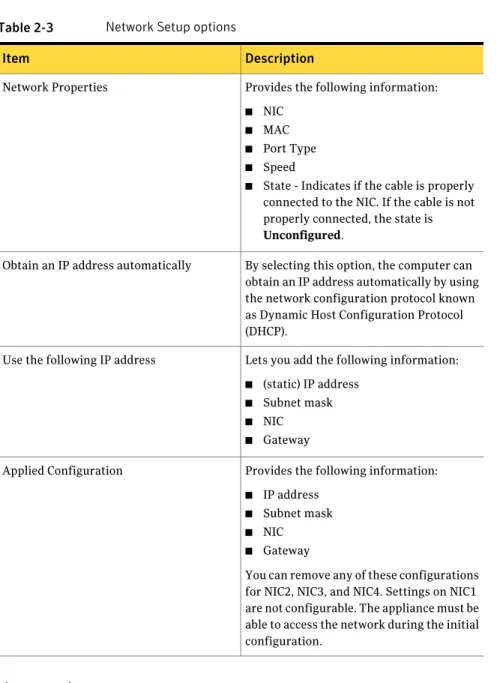
Set DNS configuration options as appropriate. See “DNS Configuration options” on page 24.Network Setup options
You can enter the IP address, subnet mask, and NIC information. See “Performing the initial configuration” on page 22.
23 Configuration
Table 2-3 Network Setup options
Description Item
Provides the following information: ■ NIC
■ MAC ■ Port Type ■ Speed
■ State - Indicates if the cable is properly connected to the NIC. If the cable is not properly connected, the state is
Unconfigured.
Network Properties
By selecting this option, the computer can obtain an IP address automatically by using the network configuration protocol known as Dynamic Host Configuration Protocol (DHCP).
Obtain an IP address automatically
Lets you add the following information: ■ (static) IP address
■ Subnet mask ■ NIC ■ Gateway Use the following IP address
Provides the following information: ■ IP address
■ Subnet mask ■ NIC ■ Gateway
You can remove any of these configurations for NIC2, NIC3, and NIC4. Settings on NIC1 are not configurable. The appliance must be able to access the network during the initial configuration.
Applied Configuration
DNS Configuration options
You can specify DNS configuration options.
See “Performing the initial configuration” on page 22. Configuration
Performing the initial configuration
Table 2-4 DNS configuration options
Description Item
Lets you enter the IP address of the DNS servers, per NIC.
To enter multiple addresses, use a comma as the delimiter between each address. Currently, only IPv4 addresses are supported.
DNS IP Address
Lets you enter one or more DNS search domain names to search when an unqualified host name is given. To enter multiple search domain names, use a comma as the delimiter between each name.
Note:If you enter any search domains, you must also provide the DNS server at the top of the page.
Search Domain
DNS suffix guidelines
Remote Desktop Protocols (RDPs) have short host names so that they work for domain and non-domain environments. The Windows computer on which you are running the browser-based Web UI should reach your Backup Exec 3600 Appliance using the short host name.
This IP address is a global setting. It does not differ per NIC.
A ping command to the short host name should show you the IP address. If the ping is not able to resolve the short host name, there is a problem with the network settings in your Windows computer.
In your Windows computer, you must add the DNS suffix so that it resolves the short host name if the appliance is in the domain. A Fully Qualified Domain Name (FQDN) name must be included in the DNS server.
The following example shows doo.rvr.symantec.com in the DNS suffix. Now you can ping all doo computers with their short host name.
Joining a domain
The appliance can be joined to a domain during or after the initial configuration. During initial configuration, the appliance is joined to the domain under the default "BEAppliance" host name. You changed this default host name to a new host name of your choosing during initial configuration. The new domain
25 Configuration
recognizes the default and new host names and requires a separate domain name for itself.
See “Configuring the appliance” on page 17.
To join a domain
1
Make sure that the "BEAppliance" host name and your new host name do not exist in the domain. If either name exists, the appliance fails to join the specified domain.Example: Change the Backup Exec appliance's new host name to “NewBEAppliance.” During the initial configuration, the host names “BEAppliance” and “NewBEAppliance” should not already exist in the domain.
2
Go to Settings > Appliance Reconfiguration > Role Configuration and enter the domain name, domain user, and domain password, and then click Save. The domain user should be the domain administrator's account, or an equivalent account that is part of the Domain Admins Group.If you have successfully joined a domain, Backup Exec services run under the context of the domain. The default Backup Exec logon account contains the domain user’s credentials.
After you have entered information on the Host/License Configuration page, a page of information regarding your new configuration displays. Messages regarding the status of your host and license changes are shown.
3
Restart the appliance.Note:It may take 10 minutes to 12 minutes for the appliance to restart completely. Symantec recommends that you log into the Web UI only after the following message disappears: "Appliance services are starting."
Confirming the initial configuration
You can verify that your initial setup and configuration steps have been completed successfully. You should run a quick test to see if the appliance functions correctly. At this time your computer should not need to be physically connected to the appliance.
See “Performing the initial configuration” on page 22. See “Configuring the appliance” on page 17.
Configuration
Confirming the initial configuration
To confirm the initial configuration
1
Open a Windows browser and enter the host name or IP address that you have set.The Backup Exec 3600 Appliance Web UI displays the login page. You do not need to log in at this time.
2
On the right side of the Backup Exec 3600 Appliance Web UI, click the SelftestConfiguration Report link.
A text file reports the items that are checked by the system. Examples of checked items include valid network settings and enabled firewall.
Installing system updates or patches
You can download and install patches or updates to the appliance after the initial configuration is completed. Symantec recommends this action before using the appliance, so that you have the most up-to-date software on your appliance before you proceed.
The process of installing updates may take a few hours. When the process has completed, two possible messages display on the Update Information page. You must restart the appliance after the system updates are installed.
See “Configuring the appliance” on page 17.
27 Configuration
To install the latest patches or updates
1
Access the Appliance Web UI.2
Go to the Manage > Appliance > Update Information page.3
Click Check and Download Updates.Any relevant patches are downloaded. A message displays “download in progress.” When the download has completed, the next step is to install the download.
4
Click Schedule.5
Click Install Now.When the installation is complete, one of the following messages displays: ■ Updates are successfully installed and the appliance needs to be rebooted. ■ Updates are partially installed and the appliance needs to be rebooted.
6
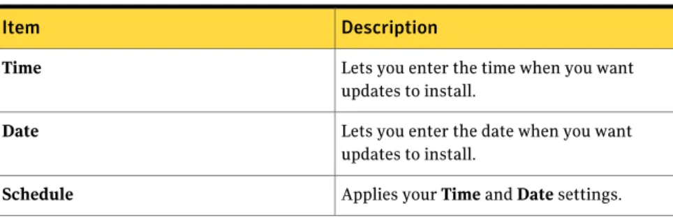
Restart the appliance now.Update information tab options
The Manage tab includes Appliance and Remote Launch tabs, each with additional options.
Configuration
Installing system updates or patches
Table 2-5 Manage > Appliance > Update Information page
Description Item
Displays the product name.
Product Name
Displays the product version.
Product Version
Displays the Show last download session log link.
Product Update
Displays the status of the most recent update, if any.
Last Update Install Status
Displays the total number of updates and the download progress. For example: "Downloading 4 out of 19 updates." This scheduled task runs once a week, at 11:00 A.M. on Sunday.
Check and download updates automatically
Lets you manually check for updates at any time. If an update is available, the Product
Update field lists all available updates.
The appliance checks for updates once a week.
Note:The appliance requires Internet access to check the availability of updates and to install updates.
Displays the total number of updates and the download progress. For example: "Downloading 4 out of 19 updates."
Check and Download Updates
Table 2-6 Manage > Appliance > Schedule Updates page
Description Item
Lets you enter the time when you want updates to install.
Time
Lets you enter the date when you want updates to install.
Date
Applies your Time and Date settings.
Schedule
29 Configuration
Table 2-6 Manage > Appliance > Schedule Updates page (continued)
Description Item
Installs any available updates on the appliance.
Note:The appliance requires Internet access to check the availability of updates and to install updates.
Install Now
Displays the most recently installed Windows and appliance updates. The update name, date of installation, and the Technical Support link display. Backup Exec software updates are not displayed.
Installed Updates
Connecting a tape device to the appliance
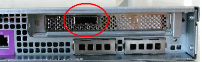
You can use the appliance and a tape device to back up data or to leverage existing tape infrastructure and investments. A SAS HBA card is installed in the Backup Exec 3600 Appliance. The card includes an external SAS port, which is located on the rear panel of the appliance, top right area.
A SAS cable ships with the appliance. Configuration
Connecting a tape device to the appliance
Several tape devices and autoloaders are compatible with the Backup Exec 3600 Appliance.
You can find a list of compatible types of storage at the following URL: http://entsupport.symantec.com/umi/V-269-2
To connect the appliance to a tape device
1
Obtain the SAS cable that shipped with the appliance.2
Insert one end of the SAS cable into the external SAS port on the SAS HBA card in the appliance.3
Insert the other end of the SAS cable into the SAS port on the rear of your tape device. An example of a typical tape device is shown. However your device may look different.4
Connect an AC power cable between the AC power socket on the tape device and an AC power source.5
Connect an AC power cable between the AC power socket on the appliance and an AC power source.6
Turn on the tape device. Allow the device to complete the startup process. The amount of time that is required for the startup process varies. Standalone devices may require one or two minutes. Devices with large libraries may require several minutes. Check the tape device vendor specifications for more information.7
Turn on the appliance.See “Configuration guidelines” on page 17.
About post-configuration tasks and options
Verify that your initial setup and configuration are successful. Then, you can set up and create backup jobs. You can set additional preferences, reconfigure initial settings, and set management parameters.
31 Configuration
You can decide which set of tasks you want to do first:
■ Set up backup jobs immediately. You can create backup jobs from the Manage > Remote Launch page on the Appliance Web UI.
See Using the Appliance Web User Interface (UI) in the Backup Exec 3600
Appliance Administrator's Guide.
■ Set additional preferences and parameters.
The three main tabs in the Backup Exec 3600 Appliance Web UI are: ■ Settings
See “Configuring system preferences on the Settings tab” on page 32. ■ Manage
See “Update information tab options” on page 28. ■ Monitor
See “Monitor tab” on page 36.
By default, the Monitor tab displays first. The Monitor tab is used most often in day-to-day operations.
Configuring system preferences on the Settings tab
You can use the Settings tab to configure the following system preferences: ■ Security
■ Network configuration
Note:Changing the primary IP address may result in loss of remote network connections. You might have to reconnect the appliance.
■ DNS configuration ■ Role configuration
■ Language and timezone configuration
To configure system preferences on the Settings tab
1
Log on to the Backup Exec 3600 Appliance.2
On the menu bar, click Settings.3
Click Appliance Reconfiguration, and then select a configuration tab to set system preferences.See “ Date and time configuration settings” on page 33. See “Hardware monitoring settings” on page 33. Configuration
About post-configuration tasks and options
See “SNMP server settings” on page 34. See “SMTP server settings” on page 35.
Date and time configuration settings
You can change the date and time settings.See Setting the Network Time Protocol (NTP) in the Backup Exec 3600 Appliance
Administrator's Guide.
Note:If you use the NTP option to change time settings or if you choose the None option, you must restart the appliance before proceeding. It may take 10 minutes to 12 minutes for the appliance to restart completely. Do not log into the Appliance Web UI until the following message disappears: "Appliance services are starting."
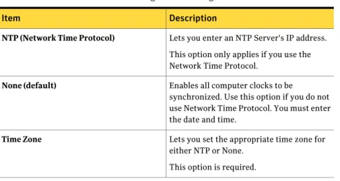
Table 2-7 Date and time configuration settings
Description Item
Lets you enter an NTP Server's IP address. This option only applies if you use the Network Time Protocol.
NTP (Network Time Protocol)
Enables all computer clocks to be
synchronized. Use this option if you do not use Network Time Protocol. You must enter the date and time.
None (default)
Lets you set the appropriate time zone for either NTP or None.
This option is required.
Time Zone
Hardware monitoring settings
The Call Home option uploads monitored information to the Symantec Call Home server at predetermined intervals. Data from the Call Home server can be retrieved to help troubleshoot issues.
See Settings > Hardware monitoring in the Backup Exec 3600 Appliance
Administrator's Guide.
The predetermined intervals are as follows:
■ Normal hardware operation data is uploaded every 30 minutes. ■ Abnormal hardware operation data is uploaded every 15 minutes.
33 Configuration
Note:Although data is uploaded regularly, the Call Home system is passive. It does not send alerts or notifications. The proxy settings let you set an intermediary device between the Backup Exec 3600 Appliance and the Symantec Call Home server.
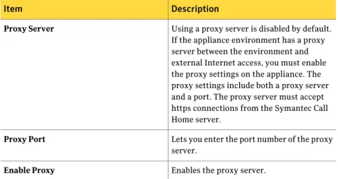
Table 2-8 Hardware monitoring settings
Description Item
Using a proxy server is disabled by default. If the appliance environment has a proxy server between the environment and external Internet access, you must enable the proxy settings on the appliance. The proxy settings include both a proxy server and a port. The proxy server must accept https connections from the Symantec Call Home server.
Proxy Server
Lets you enter the port number of the proxy server.
Proxy Port
Enables the proxy server.
Enable Proxy
SNMP server settings
You can set SNMP server information.
See Settings > Configuration > SNMP Server page in the Backup Exec 3600 Appliance
Administrator's Guide.
Table 2-9 SNMP server settings
Description Item
Lets you enter the SNMP (Simple Network Management Protocol) Server host name. You can enter a host name or an IP address to define this computer. Notifications of the alerts that are generated in the appliance are sent using this SNMP server.
SNMP Server
Lets you enter the SNMP Server port number.
If you do not enter anything for this variable, the default port is 162, which is
pre-populated in the port field.
SNMP Port
Configuration
About post-configuration tasks and options
Table 2-9 SNMP server settings (continued)
Description Item
Lets you enter the name of the community to which these alerts are sent. For example, Backup Reporting Department. Enter a value that is configured on the SNMP server. For example, enter a company name or a name such as admin_group, public, or private. If you do not enter a name, the default value is public.
SNMP Community
Lets you enable SNMP hardware monitoring.
Enable SNMP Hardware Monitoring
Lets you view the Management Information Base (MIB) file. This file contains the notification traps that are configured to monitor the appliance.
MIB file
SMTP server settings
You can set SMTP server information.
See Settings > Configuration > SMTP Server page in the Backup Exec 3600 Appliance
Administrator's Guide.
Table 2-10 SMTP server settings
Description Item
Lets you enter the name of your Simple Mail Transfer Protocol (SMTP) server.
SMTP Server Name
Lets you set the interval, in number of minutes, between the alert mails that are sent to the appliance administrator.
SMTP Notification Interval
Lets you enter the appliance administrator’s email address. You can also add multiple email addresses separated by a semi-colon.
Sender Email Address
Lets you enter the name of the SMTP server's user name.
Server User Name
Lets you enter the SMTP server's password.
Server User Password
35 Configuration
Viewing hardware component fault information
You can view details about the Backup Exec 3600 Appliance by using the following steps.
To view hardware component fault information
1
Log on to the Backup Exec 3600 Appliance.2
Click Monitor > Hardware to view hardware component fault information. See “Monitor tab” on page 36.Monitor tab
The Monitor tab displays hardware component fault information. See “Viewing hardware component fault information” on page 36.
Table 2-11 Hardware component fault information
Description Item
Displays the following information about your appliance:
■ Model
■ Software Version ■ Serial Number ■ Manufacturer
Appliance Summary
Displays the following information about the four hard disk drives (HDD) in the front panel of your appliance:
■ ID - Unique ID that is associated with each disk.
■ Enclosure ID – Enclosure where the disks are located.
■ Slot No (number) - Slot in the enclosure that contains the volume.
■ Status - Status of the media. Examples of disk status information include Frozen, Active, and so on.
■ Capacity (TB) – Terabyte capacity that is in use.
■ Type - The type of disk that is configured.
Disk
Configuration
About post-configuration tasks and options
Table 2-11 Hardware component fault information (continued)
Description Item
Displays status information about the two RAID cards that are not hot-swappable inside your appliance. One RAID card is configured as RAID1 for the OS volume, the other RAID card is configured as RAID5 for the data volume.
■ ID - Unique ID that is associated with the RAID device.
■ Name – The name of the RAID device. ■ Status - The current status of the device,
such as Optimal.
■ Capacity (GB) - The capacity of each device.
■ Type (RAID 1 or RAID 5).
RAID
Displays the following information about the fans inside your appliance:
■ ID ■ Status ■ Speed (rpm)
Fan
Displays the following information: ■ Temperature (in degrees C). ■ Type – Location of sensor, such as
“output vent”.
Temperature
You may want to confirm your initial settings or establish additional preferences before you start monitoring. After you have finalized your settings and
management options you should not have to access those tabs often.
About server roles
You can configure your appliance to manage other servers in different environments.
You can select one of the following server roles for your Backup Exec 3600 Appliance, including:
■ Central administration server
37 Configuration
See the chapter Symantec Backup Exec Central Admin Server Option in the
Symantec Backup Exec Administrator’s Guide for details.
■ Managed Backup Exec server
See the topic Push-installing a managed Backup Exec server from the central
administration server in the Symantec Backup Exec Administrator’s Guide for
details.
■ Standalone Backup Exec server
See the topic Changing a managed Backup Exec server to a standalone Backup
Exec server in the Symantec Backup Exec Administrator’s Guide for details.
About recreating selection lists after server role configuration changes
When you change the role configuration settings the appliance does not automatically change the settings in the existing backup selection lists. Existing backups fail if the backup selection list is not updated. When you have changed the role configuration, you have to recreate the selection lists to make sure that backups continue to function properly.
See the following link for more details:
http://www.symantec.com/business/support/index?page=content&id=TECH38988
About changing the host name
In this release, the host name of the appliance cannot be changed after the appliance has been configured. The host name can be set only one time, during the initial configuration. If you must change the host name again, restore the factory settings and begin the initial configuration again.
See “Performing the initial configuration” on page 22. Configuration
About server roles
Removing and replacing
components
This chapter includes the following topics: ■ About removing and replacing components ■ Removing a disk drive module
■ Replacing one disk drive module
■ About replacing more than one disk drive module ■ About replacing the appliance
■ About removing and replacing power supply modules ■ About replacing hardware
■ About hot-swappable, customer-replaceable units (CRUs)
About removing and replacing components
The Backup Exec 3600 Appliance is designed to have few customer-replaceable components. Customers should not replace any internal components in the chassis. Replaceable parts include the following:
■ Four externally accessible SAS disk drives ■ Two power supply modules
If you determine that a disk drive is faulty, you can remove the drive and replace it with a new one.
3
For static-sensitive devices, electrostatic discharge (ESD) can damage electronic components. Handle disk drives correctly to prevent damage.
CAUTION
Wear a wrist strap to prevent static discharge.
Touch a grounded metal object before removing the disk drive from the antistatic bag.
Handle a disk drive by its edges only; do not touch components on the bottom.
Note:An appliance that has fewer than three disk drives installed must have empty bays populated with drive tray baffles. Empty bays without baffles adversely affect appliance cooling.
See “Replacing one disk drive module” on page 41.
See “About replacing more than one disk drive module” on page 42. See “About replacing the appliance” on page 42.
See “About removing and replacing power supply modules” on page 42. See “About replacing hardware” on page 44.
Removing a disk drive module
The four disk drive modules in the front of the Backup Exec 3600 Appliance are labeled 0, 1, 2, 3, from left to right. If you replace more than one disk module at a time, determine which replacement disk to place into each disk slot, or bay. Label replacement disk modules with the correct slot. Label the disk modules that you remove from the appliance so that you know which bay they occupied. Removing and replacing components
Removing a disk drive module
Figure 3-1 Removing a disk drive module
To remove a disk drive module
1
Press the green release button that is located on the left side of the disk drive bay.2
Swing the handle open to disengage the hard drive.3
Slightly disengage the disk module from the drive bay and wait one or two minutes for the disk to stop spinning.4
When the drive has stopped spinning, pull it completely out of the drive bay. See “Replacing one disk drive module” on page 41.See “About replacing more than one disk drive module” on page 42.
Replacing one disk drive module
Note:Make sure that the replacement hard drive has the same physical appearance and the same connectors as the hard drive that was removed.
To replace one disk drive module
1
Go to the following Symantec Technical Support Web site to obtain instructions for replacing a defective drive:www.symantec.com/business/support/
2
With the drive tray lock fully open, orient the replacement disk drive module with the label on top and the visible components on the bottom.3
Push the disk drive module into the drive bay until it stops.4
Press the lock until it snaps shut to close the drive in the bay.41 Removing and replacing components
The drive rebuild may start the RAID controller automatically, depending on whether your RAID configuration rebuilds the virtual disk. No disaster recovery or further action is required.
About replacing more than one disk drive module
Go to the following Symantec Technical Support Web site to obtain instructions for replacing defective drives:
www.symantec.com/business/support/
Several sets of instructions must be completed if more than one disk drive requires replacement.
See the Backup Exec 3600 Administrator’s Guide for details.
About replacing the appliance
You cannot open the chassis of the appliance and replace internal components. If any internal components are faulty you must replace the entire appliance.
Warning:Any attempt to open the chassis will void your warranty.
Go to the following Symantec Technical Support Web site to obtain instructions for replacing a defective appliance:
www.symantec.com/business/support/
Several sets of instructions must be completed if an appliance requires replacement.
See the Backup Exec 3600 Administrator’s Guide for details.
About removing and replacing power supply modules
The Backup Exec 3600 Appliance has two hot-swappable power supply modules. Fans inside the modules maintain cooling through the chassis. You must make sure that both modules are connected to separate AC power sources (such as a wall outlet) and operate properly. If one power supply fails, the other power supply takes over the full power load and the system runs without interruption. If both power supply modules fail, or if one fails while you replace the other power supply module, you must turn off the system immediately. If you do not turn off the appliance, the system may overheat quickly.
Removing and replacing components
About replacing more than one disk drive module
Warning:Personal injury can occur from a hot power supply unit. Allow the power supply unit to cool before servicing.
Before touching the blade or electronic components, make sure to wear an ESD wrist strap. The strap prevents static discharge and ensures an ESD-safe environment.
Touch a grounded metal object before removing the new power supply from the antistatic bag.
Removing a power supply module
You can remove a power supply module.
To remove a power supply module
1
Press and hold the green safety lock down.2
Pull the power supply module out of Backup Exec 3600 Appliance chassis.Figure 3-2 Removing a power supply module
Replacing a power supply module
Note: Ensure that the replacement power supply module has the same physical appearance and the same connectors as the power supply that was removed.
To replace a power supply module
1
Press and hold the green safety latch.2
Slide the new power supply module into the chassis slot.3
Press firmly on the center of the power supply module to lock it in place. 43 Removing and replacing componentsAbout replacing hardware
If hardware needs to be replaced, please contact Technical Support for assistance.
About hot-swappable, customer-replaceable units
(CRUs)
The following components can be removed and replaced. ■ Four SAS externally accessible disk drives
You can remove one faulty disk drive while the appliance is turned on. Place a disk drive blank into the empty slot to prevent overheating. If more than one disk drive requires removal, contact Technical Support.
■ Two power supplies
One power supply must be turned on and functioning at all times. You can remove one of the two power supplies if needed. It is recommended to replace a faulty power supply as quickly as possible. If there is only one functioning power supply in the appliance, there is a risk if that power supply is also faulty. If both power supplies are faulty, turn off the appliance immediately. If you do not turn off the appliance, overheating of internal components is likely.
Warning:Customers must not replace any other components. Doing so will void the warranty.
Removing and replacing components
About replacing hardware
Environmental
specifications
This chapter includes the following topics: ■ About environmental specifications
About environmental specifications
The following table provides the environmental ranges that are required for proper operation of the Backup Exec 3600 Appliance.
Table 4-1 Environmental requirements
Details Component
10°C to 35°C (41°F to +95°F) Operating temperature
When the altitude ranges from -60 meters to +1,800 meters, the ambient temperature ranges from 5°C to 35°C. When the altitude ranges from 1,800 meters to 3,000 meters, the environment temperature decreases by 0.6°C when the altitude increases by 100 meters.
-40°C to +70°C (-40°F to +158°F) Storage temperature
-40°C to +70°C (-40°F to +158°F) Transportation temperature
10°C/hr (Maximum) Temperature gradient
10% RH to 85% RH Operating humidity
-30.5 meters to +3,000 meters Storage altitude
4
Table 4-1 Environmental requirements (continued)
Details Component
-30.5 meters to +3,000 meters Operating altitude
< 72 decibels, A-weighting Noise
The maximum noise of the Backup Exec 3600 Appliance when the ambient temperature is 25°C.
2550 BTU/hr System cooling
Environmental specifications
About environmental specifications